fully agreefirst of all also from my side a warm welcome here on board of our forum
You made a good decision to build this model first, before you start with bigger ones, and we will try our best to assist you as much as possible
Until now a very good start, either your work and also the log - I will follow with big interest
-

Win a Free Custom Engraved Brass Coin!!!
As a way to introduce our brass coins to the community, we will raffle off a free coin during the month of August. Follow link ABOVE for instructions for entering.
-

PRE-ORDER SHIPS IN SCALE TODAY!
The beloved Ships in Scale Magazine is back and charting a new course for 2026!
Discover new skills, new techniques, and new inspirations in every issue.
NOTE THAT OUR FIRST ISSUE WILL BE JAN/FEB 2026
You are using an out of date browser. It may not display this or other websites correctly.
You should upgrade or use an alternative browser.
You should upgrade or use an alternative browser.
La Candelaria OcCre 1:85 - First build
- Thread starter dThomas
- Start date
- Watchers 23
-
- Tags
- la candelaria occre
Great result Thomas, do you plan to add tree nails to the deck?
Hello Thomas. You have good skills and your planning to improve the kit is well thought out. Great progress thus far. I will be enjoying your build here. Cheers GrantIn the last weeks I increased the time spent working at the shipyard in order to finish planking the main deck and now it is done! Everything had been glued in place and the edges received a finish using files. The surface has been scraped smooth.The deck has been dry fitted to ensure everything will work out as expected.
View attachment 312792
View attachment 312793
The next step will be simulating nails using a pencil. Since there will be approximately one zillion nails this will take some time...
I am planning to add fake decks below the two gratings instead of just a look inside the empty hull. Therefore I need some cutouts from the basic plywood hull structure where the fake decks will be placed. I started removing material below the front grating so you will be able to see the fake deck and the mast base through the grating.
View attachment 312794
View attachment 312795
Additionally I am working on a scratch built bell tower as a replacement for the kit provided metal casting. The parts will be CNCed from walnut but I still need some practice and need to improve the process. Below you find the intended design for the pillars and a first milled test pillar. The test piece is already quite as expected but I need to improve the calibration after changing the end mill because the edge beveling is slightly off center (the image only shows the good side ).
View attachment 312796
View attachment 312797
Wow those planks look great! Were the teak strips you bought that color or did you stain them?In the last weeks I increased the time spent working at the shipyard in order to finish planking the main deck and now it is done! Everything had been glued in place and the edges received a finish using files. The surface has been scraped smooth.The deck has been dry fitted to ensure everything will work out as expected.
View attachment 312792
View attachment 312793
The next step will be simulating nails using a pencil. Since there will be approximately one zillion nails this will take some time...
I am planning to add fake decks below the two gratings instead of just a look inside the empty hull. Therefore I need some cutouts from the basic plywood hull structure where the fake decks will be placed. I started removing material below the front grating so you will be able to see the fake deck and the mast base through the grating.
View attachment 312794
View attachment 312795
Additionally I am working on a scratch built bell tower as a replacement for the kit provided metal casting. The parts will be CNCed from walnut but I still need some practice and need to improve the process. Below you find the intended design for the pillars and a first milled test pillar. The test piece is already quite as expected but I need to improve the calibration after changing the end mill because the edge beveling is slightly off center (the image only shows the good side ).
View attachment 312796
View attachment 312797
Thanks for all the positive feedback, much appreciated!
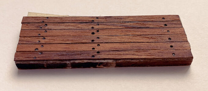
@Tobias I will not treenail the deck. I doubt that I can produce good results on these small planks (3 mm wide). Instead I tested a method using a pencil and some pressure in order to create some depth simulating a recessed nail head. You can see it in the picture of my test board below:
@GrantTyler this will be due to the fact that I spent way more time thinking about how to do something than actually doing something on the model
@Kramer the previous pictures all show untreated wood with it’s original color. The image in this post shows my test board wich had been treated (from left to right) with bees wax, teak oil and boiled linseed oil. But you can hardly see any difference between the three…
@Tobias I will not treenail the deck. I doubt that I can produce good results on these small planks (3 mm wide). Instead I tested a method using a pencil and some pressure in order to create some depth simulating a recessed nail head. You can see it in the picture of my test board below:

@GrantTyler this will be due to the fact that I spent way more time thinking about how to do something than actually doing something on the model
@Kramer the previous pictures all show untreated wood with it’s original color. The image in this post shows my test board wich had been treated (from left to right) with bees wax, teak oil and boiled linseed oil. But you can hardly see any difference between the three…
During the weekend I had enough time to work with the CNC mill. I improved the resulting accuracy by using a Z probe which allows me to just re-set the zero Z position after changing the mill bit. In the previous runs I manually reset the zero position for X, Y and Z which caused some mismatch between the runs with different bits. Now using the Z probe all three runs for the left bell tower pillar match fine and I am quite happy with the result (see picture below). I will require some additional manual finish (sanding).
The next task was to make the right pillar which is far more complicated as it has three small steps with delicate curvature. Unfortunately this steps where just to small which caused some parts to break off:
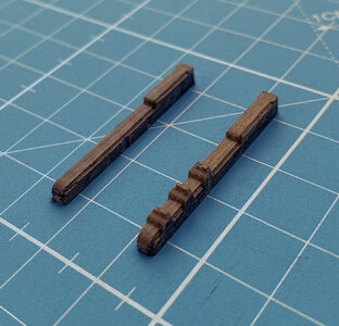
So I need to adjust the model a bit so the steps are not that fragile. I changed the height of the steps from 2 to 3mm and will give it another try next time.
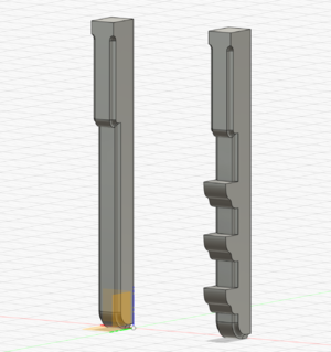
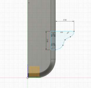
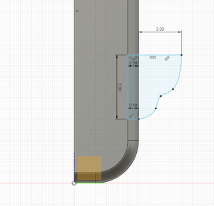
For explanation, these are the steps involved when milling the right pillar:
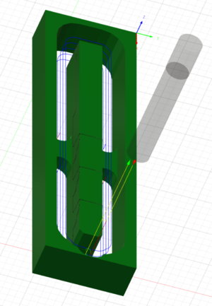
Step 1 - use 3mm corn shaped end mill along the outer shape to form the basic contour:
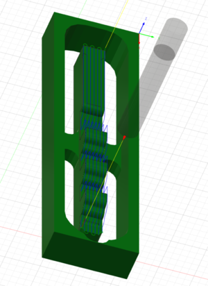
Step 2 - use 3mm corn shaped end mill to mill roughly the different heights of the model:
Step 3 - use ball tip mill for details and final 3D shape:
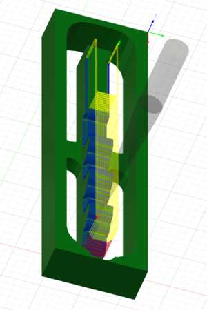
Overall I am getting better at using the CNC router, but it still keeps doing things I was not expecting it to do…
The next task was to make the right pillar which is far more complicated as it has three small steps with delicate curvature. Unfortunately this steps where just to small which caused some parts to break off:

So I need to adjust the model a bit so the steps are not that fragile. I changed the height of the steps from 2 to 3mm and will give it another try next time.


For explanation, these are the steps involved when milling the right pillar:
Step 1 - use 3mm corn shaped end mill along the outer shape to form the basic contour:

Step 2 - use 3mm corn shaped end mill to mill roughly the different heights of the model:

Step 3 - use ball tip mill for details and final 3D shape:

Overall I am getting better at using the CNC router, but it still keeps doing things I was not expecting it to do…
Beside working on the bell tower, I also made some progress on adding false decks under the two gratings of the main deck.
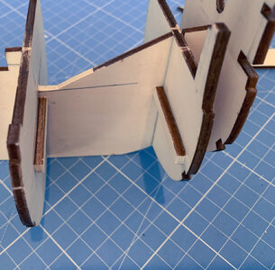
I used leftover plywood from the sheets containing the laser cut parts to build the additional decks not part of the original kit. Firstly I installed horizontal supports by glueing them on the bulkheads. These will hold the deck parts to be installed later:
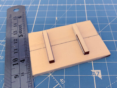
Next I joined two plywood pieces together with supports to get the new deck. This had to be done twice, one for the left side and another one for the right side:
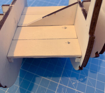
The joined pieces had been cut out roughly to fit in the required position. After they had been joined, I used files to trim them to the correct size so they fit exactly in their final place:
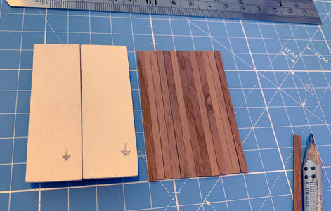
Next step was to plank the two deck pieces with 3mm Teak strips:
Then the bulkheads and all surrounding plywood was painted black, nailing has been simulated by using a pencil and the deck has been treated with beeswax mixed with coconut oil. I used the small decks to practice simulating nailing before the same technique will be applied to the much larger main deck.
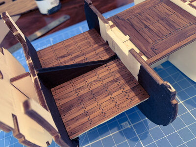
One of the bulkheads will be visible later through the grating, so I had to remove parts of it with a file and build up the visible parts with teak strips:
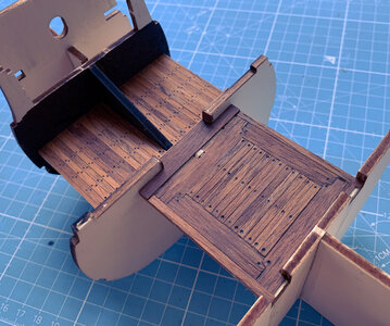
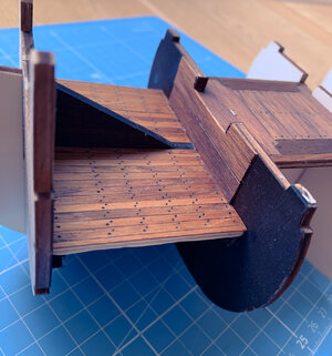
And finally this is the end result (There will be a 2mm wide walnut separator between the grating and the little lowered square deck that has to be installed later):
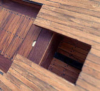
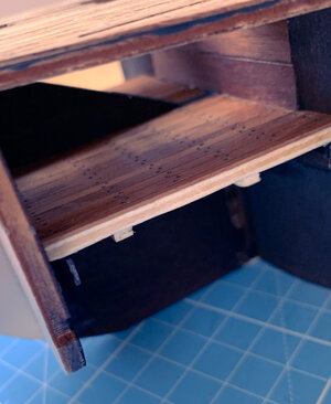
The next step on my ToDo list is the construction of the false deck for the other grating in a similar fashion.
I used leftover plywood from the sheets containing the laser cut parts to build the additional decks not part of the original kit. Firstly I installed horizontal supports by glueing them on the bulkheads. These will hold the deck parts to be installed later:

Next I joined two plywood pieces together with supports to get the new deck. This had to be done twice, one for the left side and another one for the right side:

The joined pieces had been cut out roughly to fit in the required position. After they had been joined, I used files to trim them to the correct size so they fit exactly in their final place:

Next step was to plank the two deck pieces with 3mm Teak strips:

Then the bulkheads and all surrounding plywood was painted black, nailing has been simulated by using a pencil and the deck has been treated with beeswax mixed with coconut oil. I used the small decks to practice simulating nailing before the same technique will be applied to the much larger main deck.

One of the bulkheads will be visible later through the grating, so I had to remove parts of it with a file and build up the visible parts with teak strips:


And finally this is the end result (There will be a 2mm wide walnut separator between the grating and the little lowered square deck that has to be installed later):


The next step on my ToDo list is the construction of the false deck for the other grating in a similar fashion.
Last edited:
Only very small steps in the last weeks but now it ist time for an update!
I have been working at the second false deck below the rear grating.
I started by marking the areas that I have to cut out of the plywood structure.
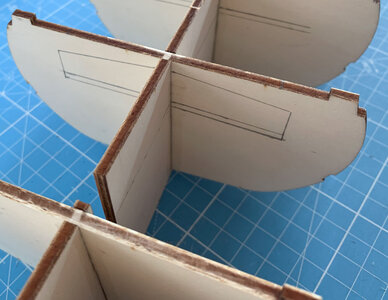
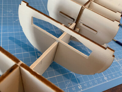
Next step was to construct the deck from scrap plywood left over from the laser cut parts.
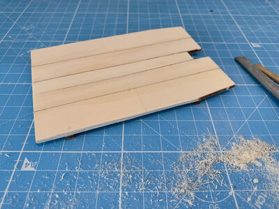
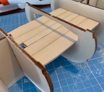
To simulate deck beams a plywood support structure has been added and the visible parts have been covered with teak strips.
Additionally most of the plywood had been painted black.
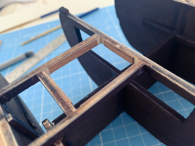
I took the chance to practice simulating nails for the main deck planking. The false deck is planked using the same pattern as the main deck so I can see what it will look like when I add simulated nails to the main deck.
I made the pillars holding the beams from walnut pieces using an Exacto knive files and sanding.
This really was a fun exercise albeit the details are so small that you can’t really see them with the naked eye.
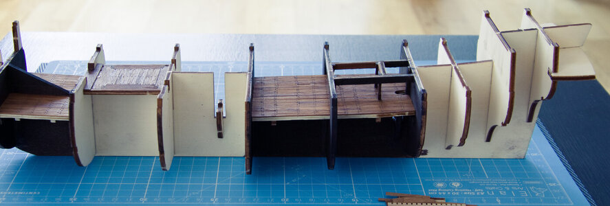
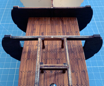
After I did all this I thought it would be a pity if all this would be nearly invisible on the final model. So I decided to make the grating removable so you can take it away and look inside!
But this produces new challenges, but that’s a topic for the next post…
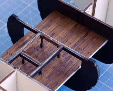
I have been working at the second false deck below the rear grating.
I started by marking the areas that I have to cut out of the plywood structure.


Next step was to construct the deck from scrap plywood left over from the laser cut parts.


To simulate deck beams a plywood support structure has been added and the visible parts have been covered with teak strips.
Additionally most of the plywood had been painted black.

I took the chance to practice simulating nails for the main deck planking. The false deck is planked using the same pattern as the main deck so I can see what it will look like when I add simulated nails to the main deck.
I made the pillars holding the beams from walnut pieces using an Exacto knive files and sanding.
This really was a fun exercise albeit the details are so small that you can’t really see them with the naked eye.


After I did all this I thought it would be a pity if all this would be nearly invisible on the final model. So I decided to make the grating removable so you can take it away and look inside!
But this produces new challenges, but that’s a topic for the next post…

Last edited:
That teak looks fantastic! Great work as usual!Beside working on the bell tower, I also made some progress on adding false decks under the two gratings of the main deck.
I used leftover plywood from the sheets containing the laser cut parts to build the additional decks not part of the original kit. Firstly I installed horizontal supports by glueing them on the bulkheads. These will hold the deck parts to be installed later:
View attachment 314985
Next I joined two plywood pieces together with supports to get the new deck. This had to be done twice, one for the left side and another one for the right side:
View attachment 314986
The joined pieces had been cut out roughly to fit in the required position. After they had been joined, I used files to trim them to the correct size so they fit exactly in their final place:
View attachment 314987
Next step was to plank the two deck pieces with 3mm Teak strips:
View attachment 314988
Then the bulkheads and all surrounding plywood was painted black, nailing has been simulated by using a pencil and the deck has been treated with beeswax mixed with coconut oil. I used the small decks to practice simulating nailing before the same technique will be applied to the much larger main deck.
View attachment 315014
One of the bulkheads will be visible later through the grating, so I had to remove parts of it with a file and build up the visible parts with teak strips:
View attachment 315015
View attachment 315016
And finally this is the end result (There will be a 2mm wide walnut separator between the grating and the little lowered square deck that has to be installed later):
View attachment 315012
View attachment 315013
The next step on my ToDo list is the construction of the false deck for the other grating in a similar fashion.
Thank you!That teak looks fantastic! Great work as usual!
The teak was really a good choice. I apply only a mixture of bees wax and coconut oil with a finger and wipe it of using a cloth and it looks brilliant!
Beside that it’s good to read that you will be able to continue working on the Norske Löve soon. I am looking forward to see some new images of your model.
It’s time for a progress update:
As mentioned I decided to make the gratings removable, so it is possible to have a look inside the model. In order to archive this, I need to construct a framing that will hold the gratings instead of just glueing them on top of the deck.
So I created the 3D models of the frame parts. Maybe it is helpful for someone to show the involved steps, so I will show the construction of one piece in detail:
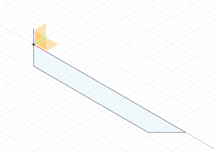
First create the basic shape of the part to construct.
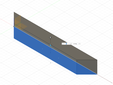
Extrude it upward by the required total height.
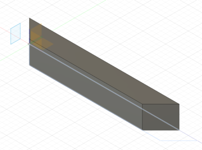
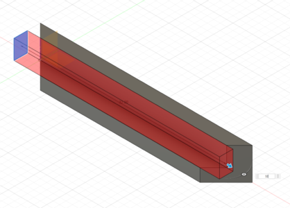
Create the rim that the gratings will rest upon by extruding and subtracting a rectangle shape.
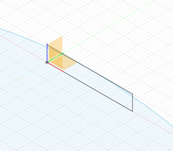
To create the top curvature a circle and a rectangle representing the parts bounds were created.
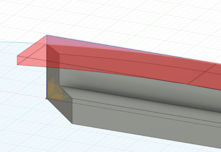
Extrude and subtract the appropriate intersecting shape of the circle and the rectangle.
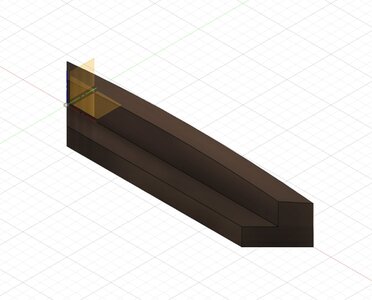
And this is the resulting part.
Creating the CNC program to mill the part comes next
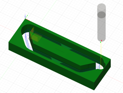
Mill along the part’s outer shape.
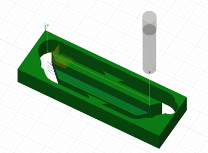
Plane operation to create the rim.
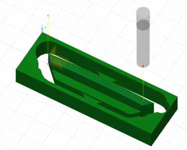
Finally a parallel operation to create the curvature.
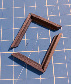
After all parts have been milled, cleaned and roughly finished I glued the together using white PVA glue.
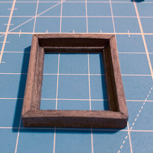
This is one of the two resulting frames.
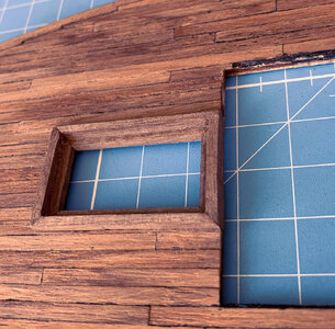
Since the frames need to be inserted in the laser cut deck opening instead of glueing them on top, the openings had to be extended using files. This is the other frame dry fitted (both deck and frame still need finishing)
And finally after all these steps, I came to the conclusion, that the rim is just too wide (2mm). So I am currently making it smaller using files. I will reduce the with to 1mm so it is just the same width as the grating parts.
Currently I am constructing the models for the gratings, the first one had just been completed:
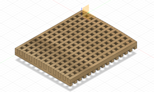
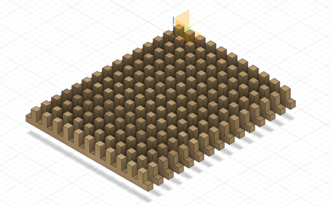
These will be milled from 3mm pear wood (just arrived at the shipyard). But I am still waiting for the required 0.8 mm milling bit to arrive (I had one but unfortunately I broke it during my first CNC tests after I got the machine. Is this button up or down direction? … crack … oops that was the wrong direction … and the tiny 0.8 mm bit stuck inside the board and broke off)
The next post will hopefully show the resulting grating…
As mentioned I decided to make the gratings removable, so it is possible to have a look inside the model. In order to archive this, I need to construct a framing that will hold the gratings instead of just glueing them on top of the deck.
So I created the 3D models of the frame parts. Maybe it is helpful for someone to show the involved steps, so I will show the construction of one piece in detail:

First create the basic shape of the part to construct.

Extrude it upward by the required total height.


Create the rim that the gratings will rest upon by extruding and subtracting a rectangle shape.

To create the top curvature a circle and a rectangle representing the parts bounds were created.

Extrude and subtract the appropriate intersecting shape of the circle and the rectangle.

And this is the resulting part.
Creating the CNC program to mill the part comes next

Mill along the part’s outer shape.

Plane operation to create the rim.

Finally a parallel operation to create the curvature.

After all parts have been milled, cleaned and roughly finished I glued the together using white PVA glue.

This is one of the two resulting frames.

Since the frames need to be inserted in the laser cut deck opening instead of glueing them on top, the openings had to be extended using files. This is the other frame dry fitted (both deck and frame still need finishing)
And finally after all these steps, I came to the conclusion, that the rim is just too wide (2mm). So I am currently making it smaller using files. I will reduce the with to 1mm so it is just the same width as the grating parts.
Currently I am constructing the models for the gratings, the first one had just been completed:


These will be milled from 3mm pear wood (just arrived at the shipyard). But I am still waiting for the required 0.8 mm milling bit to arrive (I had one but unfortunately I broke it during my first CNC tests after I got the machine. Is this button up or down direction? … crack … oops that was the wrong direction … and the tiny 0.8 mm bit stuck inside the board and broke off)
The next post will hopefully show the resulting grating…
Last edited:
Currently I am working on several task in parallel:
I completed the rear frame for the gratings including reducing the thickness and the final sanding. It has been dry fitted to the deck and is ready to be permanently glued to the deck. Next up is finalizing the frame for the front grating.
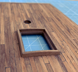
While I am still waiting for the 0.8mm milling bits to arrive, which are required for producing the actual gratings, I started planning how to produce barrels.
Since the gratings will be removable and provide the ability to look inside at the lower deck, it would be nice to see some actual equipment stored there. Therefore I started to figure out what might have been located around the gratings on the lower deck.
Unfortunately I have no detailed plans of this ship available, only the plans from Occre. Actually I find it difficult to find details regarding spanish ships, I found the monograph of the La Mahonesa from Ancre which could contain relevant informations since it is from the same time period but is quite expensive especially since I am not planning to actually build the ship.
So actually I have no clue what was the purpose of the space below the rear grating (I would be glad if anyone could provide some advice on the usage of this space).
But I decided it would be nice to show two or three barrels stored next to the grating on the lower deck.
So I started to think about how to produce barrels and I this is what I came up to:
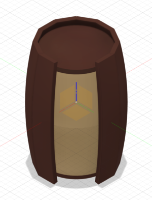
The barrel will consist of a core milled out of lime wood (combination of an upper and a lower part glued together) and will be planked with teak strips.
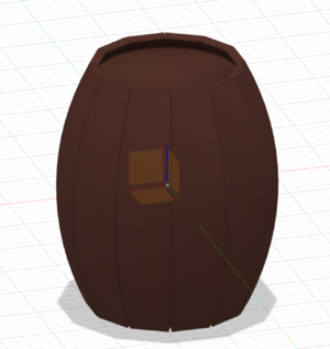
In Fusion 360 I created a parameter based model with adjustable, radius, height, outer segment count and so on including a visualization of the expected outcome. I hadn't planned this, it was just quite fun to do, so I spent quite some time playing around.
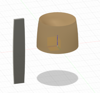
Here you can see the parts that I actually will produce using the CNC mill (the core parts and appropriate shaped planks):
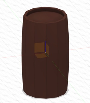
And just to demonstrate the parameter based geometry, some different barrel version:
Below the front grating I plan to show the stored anchor cable, but I am not sure if that is realistic. So I ask you if it makes sense to store the anchor cable on the lower deck in the bow between the bowsprit base and the mortar base? (See picture of the location below)
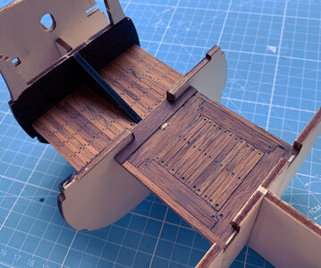
(This part also needs some adjustments since I realized, that my planned mast base is incorrect. Therefore this needs to be corrected and a part of the black triangle shaped plywood piece needs to be removed in order to create a correct mast base)
I completed the rear frame for the gratings including reducing the thickness and the final sanding. It has been dry fitted to the deck and is ready to be permanently glued to the deck. Next up is finalizing the frame for the front grating.

While I am still waiting for the 0.8mm milling bits to arrive, which are required for producing the actual gratings, I started planning how to produce barrels.
Since the gratings will be removable and provide the ability to look inside at the lower deck, it would be nice to see some actual equipment stored there. Therefore I started to figure out what might have been located around the gratings on the lower deck.
Unfortunately I have no detailed plans of this ship available, only the plans from Occre. Actually I find it difficult to find details regarding spanish ships, I found the monograph of the La Mahonesa from Ancre which could contain relevant informations since it is from the same time period but is quite expensive especially since I am not planning to actually build the ship.
So actually I have no clue what was the purpose of the space below the rear grating (I would be glad if anyone could provide some advice on the usage of this space).
But I decided it would be nice to show two or three barrels stored next to the grating on the lower deck.
So I started to think about how to produce barrels and I this is what I came up to:

The barrel will consist of a core milled out of lime wood (combination of an upper and a lower part glued together) and will be planked with teak strips.
In Fusion 360 I created a parameter based model with adjustable, radius, height, outer segment count and so on including a visualization of the expected outcome. I hadn't planned this, it was just quite fun to do, so I spent quite some time playing around.
Here you can see the parts that I actually will produce using the CNC mill (the core parts and appropriate shaped planks):

And just to demonstrate the parameter based geometry, some different barrel version:


Below the front grating I plan to show the stored anchor cable, but I am not sure if that is realistic. So I ask you if it makes sense to store the anchor cable on the lower deck in the bow between the bowsprit base and the mortar base? (See picture of the location below)

(This part also needs some adjustments since I realized, that my planned mast base is incorrect. Therefore this needs to be corrected and a part of the black triangle shaped plywood piece needs to be removed in order to create a correct mast base)
Maybe I should explain why I am dealing with all these details in this early stage of the build. The kits design requires the decks to be installed permanently before the builder can begin with planking the hull. Since the deck can not be inserted after hull planking, everything on my false decks will get inaccessible after the hull has been planked. This results in the fact that I have to construct all details on the lower decks before I can install the decks and start planking.
In order to show the planned modifications at the front grating I made a rough sketch explaining what I plan to change:
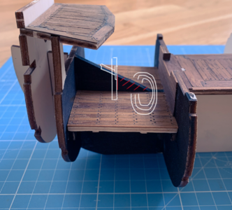
I will remove some of the plywood (red) so I can construct a proper mast base and place the anchor cable next to it (white).
As said earlier any feedback is welcome since I am not really sure if this all would be realistic.
In order to show the planned modifications at the front grating I made a rough sketch explaining what I plan to change:

I will remove some of the plywood (red) so I can construct a proper mast base and place the anchor cable next to it (white).
As said earlier any feedback is welcome since I am not really sure if this all would be realistic.
Fabelhaft. alles wunderbar gemact. es ist ein sehr gutes idea-kein pause zumachen-when kein dumaterial hast.Maybe I should explain why I am dealing with all these details in this early stage of the build. The kits design requires the decks to be installed permanently before the builder can begin with planking the hull. Since the deck can not be inserted after hull planking, everything on my false decks will get inaccessible after the hull has been planked. This results in the fact that I have to construct all details on the lower decks before I can install the decks and start planking.
In order to show the planned modifications at the front grating I made a rough sketch explaining what I plan to change:
View attachment 332528
I will remove some of the plywood (red) so I can construct a proper mast base and place the anchor cable next to it (white).
As said earlier any feedback is welcome since I am not really sure if this all would be realistic.
eine frage?hast tu ein E-.MAIL addresse-mein ist peandersen@telefonica,net- undfur kan ich besser hilfen-mere alf 50 jahre model gebaut mit round 40 modelle. viel material uner spanishe shife..
Last edited by a moderator:
Good morning. Unfortunately my knowledge of these ships is limited so I cannot advise on the accuracy of what you are doing. I do however enjoy your approach and thought process in your modeling. Your work is amazing. Cheers GrantCurrently I am working on several task in parallel:
I completed the rear frame for the gratings including reducing the thickness and the final sanding. It has been dry fitted to the deck and is ready to be permanently glued to the deck. Next up is finalizing the frame for the front grating.
View attachment 332518
While I am still waiting for the 0.8mm milling bits to arrive, which are required for producing the actual gratings, I started planning how to produce barrels.
Since the gratings will be removable and provide the ability to look inside at the lower deck, it would be nice to see some actual equipment stored there. Therefore I started to figure out what might have been located around the gratings on the lower deck.
Unfortunately I have no detailed plans of this ship available, only the plans from Occre. Actually I find it difficult to find details regarding spanish ships, I found the monograph of the La Mahonesa from Ancre which could contain relevant informations since it is from the same time period but is quite expensive especially since I am not planning to actually build the ship.
So actually I have no clue what was the purpose of the space below the rear grating (I would be glad if anyone could provide some advice on the usage of this space).
But I decided it would be nice to show two or three barrels stored next to the grating on the lower deck.
So I started to think about how to produce barrels and I this is what I came up to:
View attachment 332517
The barrel will consist of a core milled out of lime wood (combination of an upper and a lower part glued together) and will be planked with teak strips.
In Fusion 360 I created a parameter based model with adjustable, radius, height, outer segment count and so on including a visualization of the expected outcome. I hadn't planned this, it was just quite fun to do, so I spent quite some time playing around.
Here you can see the parts that I actually will produce using the CNC mill (the core parts and appropriate shaped planks):
View attachment 332520
And just to demonstrate the parameter based geometry, some different barrel version:
View attachment 332521
View attachment 332522
Below the front grating I plan to show the stored anchor cable, but I am not sure if that is realistic. So I ask you if it makes sense to store the anchor cable on the lower deck in the bow between the bowsprit base and the mortar base? (See picture of the location below)
View attachment 332527
(This part also needs some adjustments since I realized, that my planned mast base is incorrect. Therefore this needs to be corrected and a part of the black triangle shaped plywood piece needs to be removed in order to create a correct mast base)
- Joined
- Oct 17, 2020
- Messages
- 1,691
- Points
- 488

Hi dTommaso, as I see it, the instructions of the Kit to follow have a reason for mountable if instead you do it your way and very differentMaybe I should explain why I am dealing with all these details in this early stage of the build. The kits design requires the decks to be installed permanently before the builder can begin with planking the hull. Since the deck can not be inserted after hull planking, everything on my false decks will get inaccessible after the hull has been planked. This results in the fact that I have to construct all details on the lower decks before I can install the decks and start planking.
In order to show the planned modifications at the front grating I made a rough sketch explaining what I plan to change:
View attachment 332528
I will remove some of the plywood (red) so I can construct a proper mast base and place the anchor cable next to it (white).
As said earlier any feedback is welcome since I am not really sure if this all would be realistic.
This will be mostly my last message here on S, O, S..Fabelhaft. alles wunderbar gemact. es ist ein sehr gutes idea-kein pause zumachen-when kein dumaterial hast.
eine frage?hast tu ein E-.MAIL addresse-mein ist peandersen@telefonica,net- ich habe einige problema mit den management, undfur kan ich besser hilfen-mere alf 50 jahre model gebaut mit round 40 modelle. viel material uner spanishe shife..
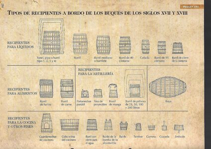
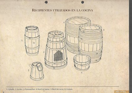
As I wrote -in German- I have a high amount (as some has already gone to the waste bin- of Spanish warships from the year1700 to 1800.I have built not all but nearly the most important Spanish ships in the Trafalgerbattle. I have downloaded all the instruction manuals of each ship, drawings and painting material etc.
I am Danish born on the Nord Sea Cost-kuste- neat 80 years ago, the since 1978 I WAS TRANSFERRED TO SPAIN, TO OPEN UP A NEW OFFICE. AND HAVE BEEN HERE SINCE. the added picture is mainly from a book: MANUAL ARQUITECTURA NAVAL - about 1000 pages, which I still have for FREE- only transport cost to be paid-20-30 €
I AM NO LONGER ACTIVE ON S.O.S. BUT CAN BE CONTACTED ON MY E-MAIL: PEANDERSEN@TELEFONICA. NET.
GOOD BYE-AUFWIEDERSEEN.
EL CAPI.
Last edited:


