-

Win a Free Custom Engraved Brass Coin!!!
As a way to introduce our brass coins to the community, we will raffle off a free coin during the month of August. Follow link ABOVE for instructions for entering.
-

PRE-ORDER SHIPS IN SCALE TODAY!
The beloved Ships in Scale Magazine is back and charting a new course for 2026!
Discover new skills, new techniques, and new inspirations in every issue.
NOTE THAT OUR FIRST ISSUE WILL BE JAN/FEB 2026
You are using an out of date browser. It may not display this or other websites correctly.
You should upgrade or use an alternative browser.
You should upgrade or use an alternative browser.
La Salamandre 1752 1:48 (CAF) by Salty
- Thread starter Salty
- Start date
- Watchers 24
-
- Tags
- caf model la salamandre
- Joined
- Mar 1, 2023
- Messages
- 144
- Points
- 213

Thanks to all visitors lately…
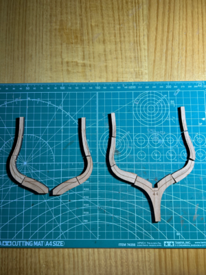
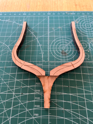
Frame 45 is the stern frame.
There have been a few posts in logs by Uwek, ADC and BigMike about this frame and I am grateful to have them as a reference point. I also had a good look at the CAF plans and Bourdout an Berti monograph as well. I have a reasonable idea what has to be done, but I can’t say I am that confident all the same.
At its base, frame 45 sits on the stern deadwood and butts up against frame 44 but the floor timbers are angled 10 degrees aft (see previous post).
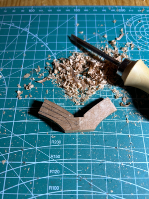
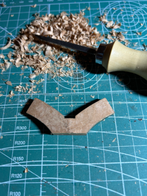
The cant is created by having a double thickness in the floor timbers in forward layer (on the left) of the frame.
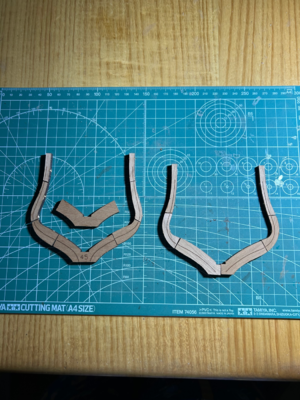
The floor timbers on the left are stuck together and wedges are cut from the forward face.
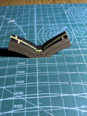
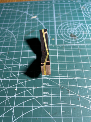
Frame 45 is the stern frame.
There have been a few posts in logs by Uwek, ADC and BigMike about this frame and I am grateful to have them as a reference point. I also had a good look at the CAF plans and Bourdout an Berti monograph as well. I have a reasonable idea what has to be done, but I can’t say I am that confident all the same.
At its base, frame 45 sits on the stern deadwood and butts up against frame 44 but the floor timbers are angled 10 degrees aft (see previous post).
The cant is created by having a double thickness in the floor timbers in forward layer (on the left) of the frame.

The floor timbers on the left are stuck together and wedges are cut from the forward face.


Last edited:
- Joined
- Mar 1, 2023
- Messages
- 144
- Points
- 213

Good work
I can remember that frame 45 was difficult to make, and I just checked my building log - maybe these posts are helping
I can remember that frame 45 was difficult to make, and I just checked my building log - maybe these posts are helping
LA SALAMANDRE, bomb ketch - POF - (CAF-models, 1/48)
I don’t think you made the error. It is clear in your photos the outside pieces are too short.
shipsofscale.com
LA SALAMANDRE, bomb ketch - POF - (CAF-models, 1/48)
Yesterday evening I could also work on the other side of the hawse pieces of the La Salamandre ......with inside sanding and dry fit (once more only with double sided adhesive tape) the first two photos showing the seven parts for each side inside the temporary jig view towards inside...
shipsofscale.com
- Joined
- Mar 1, 2023
- Messages
- 144
- Points
- 213

Thanks to everyone who has been following my progress.
Uwek, your detailed descriptions have helped greatly. If you had a dollar for every time I have visited your log, you would be a rich man…
Frame 45 continued…
The part that caused me some difficulty visualising the end result. The angle created in the previous post does not continue all the way up the frame. Rather it stops after the floor timbers and the futtocks and top timbers maintain a constant distance from those in frame 44 (4 mm or so according to Bourdoit and Berti). This why the sides of the ends of the floor timber are parallel to the keel and not angled at 10 degrees.
I then just built the rest of the frame in the usual way.
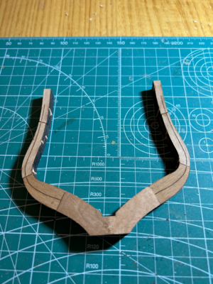
One final task was to redraw the bevelling lines.
That is as far as I intend to go at this stage. I know the the frame needs to be thinned, but I want to build the stern post to see how the transom timbers fit before I do anything further.
Uwek, your detailed descriptions have helped greatly. If you had a dollar for every time I have visited your log, you would be a rich man…
Frame 45 continued…
The part that caused me some difficulty visualising the end result. The angle created in the previous post does not continue all the way up the frame. Rather it stops after the floor timbers and the futtocks and top timbers maintain a constant distance from those in frame 44 (4 mm or so according to Bourdoit and Berti). This why the sides of the ends of the floor timber are parallel to the keel and not angled at 10 degrees.
I then just built the rest of the frame in the usual way.

One final task was to redraw the bevelling lines.
That is as far as I intend to go at this stage. I know the the frame needs to be thinned, but I want to build the stern post to see how the transom timbers fit before I do anything further.
- Joined
- Mar 1, 2023
- Messages
- 144
- Points
- 213

I feel like I have finished the first stage of La Salamandre now the frames have been glued up.
I didn’t mention it in my first post in this diary, but this is my first model ship. Although I probably should have started something more modest, I have been encouraged by reading about the efforts of others on this forum. I have found the building to be enjoyable to date. From my perspective, patience and persistence are the key.
Posting anything on the internet is also something new and I hope you have found some of it interesting. Most of my photography leaves a bit to be desired, but you get the general idea. I must admit to being somewhat surprised by the number of people who have visited my diary to date.
The next stage is to build the keel.
Good morning. POF models are something else. I only have admiration for you guys who accept this challenge and pull it off. Looking spot on this far. Cheers GrantI feel like I have finished the first stage of La Salamandre now the frames have been glued up.
I didn’t mention it in my first post in this diary, but this is my first model ship. Although I probably should have started something more modest, I have been encouraged by reading about the efforts of others on this forum. I have found the building to be enjoyable to date. From my perspective, patience and persistence are the key.
Posting anything on the internet is also something new and I hope you have found some of it interesting. Most of my photography leaves a bit to be desired, but you get the general idea. I must admit to being somewhat surprised by the number of people who have visited my diary to date.
The next stage is to build the keel.
- Joined
- Oct 17, 2020
- Messages
- 1,691
- Points
- 488

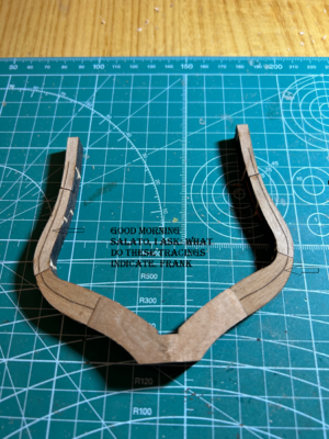
Good morning Salato, I ask: what do these tracings indicate. FrankThanks to everyone who has been following my progress.
Uwek, your detailed descriptions have helped greatly. If you had a dollar for every time I have visited your log, you would be a rich man…
Frame 45 continued…
The part that caused me some difficulty visualising the end result. The angle created in the previous post does not continue all the way up the frame. Rather it stops after the floor timbers and the futtocks and top timbers maintain a constant distance from those in frame 44 (4 mm or so according to Bourdoit and Berti). This why the sides of the ends of the floor timber are parallel to the keel and not angled at 10 degrees.
I then just built the rest of the frame in the usual way.
View attachment 373848
One final task was to redraw the bevelling lines.
That is as far as I intend to go at this stage. I know the the frame needs to be thinned, but I want to build the stern post to see how the transom timbers fit before I do anything further.
- Joined
- Mar 1, 2023
- Messages
- 144
- Points
- 213

Frank, the laser marking shows where the frames should be bevelled to create the curves on the outside and inside of the hull. In the picture in your post, the marking shows the bevel for the inside of the hull and there are markings on the other face showing the bevel for the outside. The markings take the guesswork out of bevelling and seem quite accurate, matching the frame plans in Boudriot and Berti’s monograph on La Salamandre.
I only have the frames glued up, but not yet bevelled, but I hope to start that work quite soon. I will post pictures as I go.
- Joined
- Oct 17, 2020
- Messages
- 1,691
- Points
- 488

Hi Salty , Thank you for your reply. FrankFrank, the laser marking shows where the frames should be bevelled to create the curves on the outside and inside of the hull. In the picture in your post, the marking shows the bevel for the inside of the hull and there are markings on the other face showing the bevel for the outside. The markings take the guesswork out of bevelling and seem quite accurate, matching the frame plans in Boudriot and Berti’s monograph on La Salamandre.
I only have the frames glued up, but not yet bevelled, but I hope to start that work quite soon. I will post pictures as I go.
- Joined
- Mar 1, 2023
- Messages
- 144
- Points
- 213

- Joined
- Mar 1, 2023
- Messages
- 144
- Points
- 213

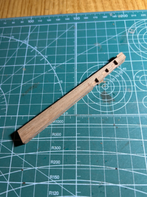
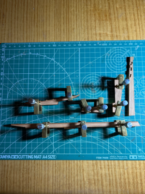
I have all the keel parts for the stern separated from the billets (each component of the keel has two halves) and have glued them up ready for cleaning the charred surfaces:
I found this video on YouTube on wooden boat building which is worth a look if you have a spare minute:
Fremad II Restoration - Compilation (2016-2020)
There is a segment on caulking the hull in the middle. Amazing how precisely everything is done, almost down to the millimetre.

I found this video on YouTube on wooden boat building which is worth a look if you have a spare minute:
Fremad II Restoration - Compilation (2016-2020)
There is a segment on caulking the hull in the middle. Amazing how precisely everything is done, almost down to the millimetre.
Last edited:
- Joined
- Mar 1, 2023
- Messages
- 144
- Points
- 213

One decision to be made is how to treat the seams in the keel. I am trying to avoid the use of the word “caulking”. Strictly speaking, I think caulking is material used to stop leaks in joints. I don’t think timbers in the keel were caulked as such but were lined with tar and flannel to stop the spread of rot.
It seems to be a personal decision as much as anything. Some modellers don’t use anything, and those that do use a variety of methods - pencil, coloured paper and coloured glue.
I am trying to build a traditional model after the style of Boudroit and Frolich (not that I think for one moment I can match them). Frohlich recommends coloured paper, but I can’t find any specific reference to the keel, only to hull and deck planking (although I stand to be corrected). It also seems that many of the joints in the keel are spanned by rabbet which would have the effect of obscuring any caulking. Further, some of the joints in the kit are not present in Boudroit and Berti.
As a result, I don’t think I will treat the keel. To my mind at least, it’s partly about what is accurate historically, but also partly about how models are built as well.
Anyway, I would be interested in your thoughts - what you do and why you do it that way.
- Joined
- Mar 1, 2023
- Messages
- 144
- Points
- 213

Thanks to everyone who is keeping up with my diary. I would be happy to try to answer any questions you might have about the kit or how I have gone about something (based on my very limited experience).
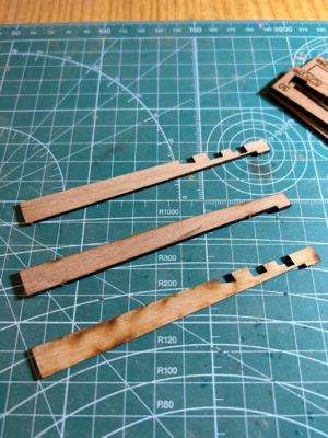
Here are the cleaned pieces of the stern section of the keel ready for assembly:
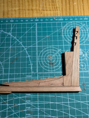
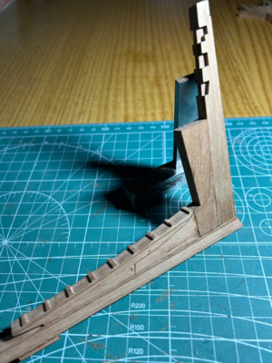
A lot of care was needed when removing the laser charring to get the pieces to fit. The last thing you need is to get impatient and try to remove too much material too quickly. The notches were also quite time fiddley. I used a razor blade to slice the charring off the faces and clean up where they meet the keel.
Here is the result:
Here are the cleaned pieces of the stern section of the keel ready for assembly:

A lot of care was needed when removing the laser charring to get the pieces to fit. The last thing you need is to get impatient and try to remove too much material too quickly. The notches were also quite time fiddley. I used a razor blade to slice the charring off the faces and clean up where they meet the keel.
Here is the result:

- Joined
- Mar 1, 2023
- Messages
- 144
- Points
- 213

- Joined
- Mar 1, 2023
- Messages
- 144
- Points
- 213

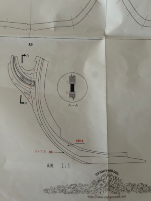
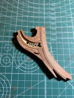
Before going further, I need to do something about the decorative insert I referred to in post #25.
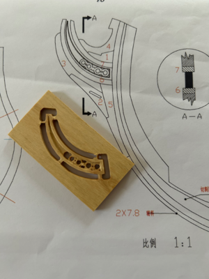
I have discovered looking at other buildings logs on this site that there are probably two versions of the insert - the first is ADC (CNC milled?) and the second is Uwek (laser?).
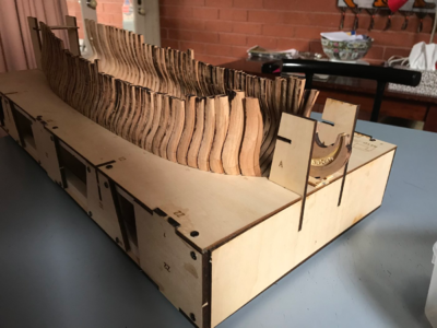
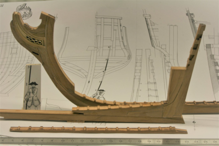
I appear to have the second type, so the “hole” is not a machining error, it is just how the piece is made.
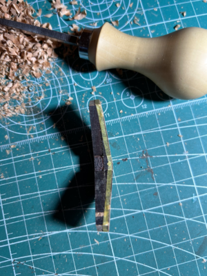
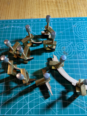
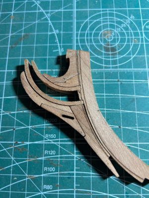
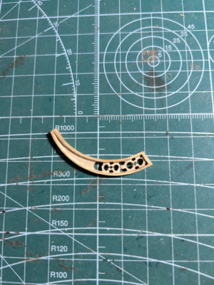
As a result, I decided to clean up the four holes at the base and leave the section to the left as it is. In any event, it took quite a while as I had to drill and the carefully enlarge the holes with a very sharp violin maker’s knife.
There was a bit of work to do on the outer section as the edges weren’t square because the top face is narrower than the bottom face. The outer frame also had to be narrowed as well to fit the other pieces in the stem as well.
Here is the final result

I have discovered looking at other buildings logs on this site that there are probably two versions of the insert - the first is ADC (CNC milled?) and the second is Uwek (laser?).


I appear to have the second type, so the “hole” is not a machining error, it is just how the piece is made.
As a result, I decided to clean up the four holes at the base and leave the section to the left as it is. In any event, it took quite a while as I had to drill and the carefully enlarge the holes with a very sharp violin maker’s knife.
There was a bit of work to do on the outer section as the edges weren’t square because the top face is narrower than the bottom face. The outer frame also had to be narrowed as well to fit the other pieces in the stem as well.
Here is the final result

Last edited:
- Joined
- Apr 20, 2020
- Messages
- 6,241
- Points
- 738

looks great 


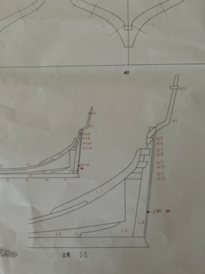
Thanks to everyone for visiting my diary. Progress is slow, but steady…
Here is the finished stem section.View attachment 378278

