-

Win a Free Custom Engraved Brass Coin!!!
As a way to introduce our brass coins to the community, we will raffle off a free coin during the month of August. Follow link ABOVE for instructions for entering.
-

PRE-ORDER SHIPS IN SCALE TODAY!
The beloved Ships in Scale Magazine is back and charting a new course for 2026!
Discover new skills, new techniques, and new inspirations in every issue.
NOTE THAT OUR FIRST ISSUE WILL BE JAN/FEB 2026
You are using an out of date browser. It may not display this or other websites correctly.
You should upgrade or use an alternative browser.
You should upgrade or use an alternative browser.
I don’t think you made the error. It is clear in your photos the outside pieces are too short.
Thanks for the confirmation....... I was in doubt, if I did something wrong -> so I will go further with the assembly
@janos : i agree with you completely. The overall quality is definitive the best available in moment. For the international market the Chinese should only start to make good and more detailed manuals and drawings for the kits
English translations can be Sealy fixed by almost anyone who knows a bit about computers.
I'm no wiz, but I can take a photo on my phone if the Chinese text and using google translate I can have any language that I want.
The English version is quite good but it's slightly pigeon English. Even though, it's still a very good guide, and anyone should be able to follow the instructions.
Gteg
Yes, thanks, this would be a possibility.......but unfortunately there is also no Chinese Text manual with the kit. There are only appr. 50 small sketches of 5 to 5 cm showing some details.....the only real Chinese Text are the content listings....but in some years, when there are more orders from outside China, they will work on the manuals, this is for Sure.English translations can be Sealy fixed by almost anyone who knows a bit about computers.
I'm no wiz, but I can take a photo on my phone if the Chinese text and using google translate I can have any language that I want.
The English version is quite good but it's slightly pigeon English. Even though, it's still a very good guide, and anyone should be able to follow the instructions.
Gteg
The best research to check how to do something are the building logs available on Chinese or Russian web-pages. Therefore, it is one of the main reasons, why I am making my building log so in detail, that somebody else can see something, what to do or not to do......
Good fix Uwe!!
This is the beauty of the (good) kits... you just have to grab the next part and assemble it. No worry about material whether you've got it or not, drawing the parts on timber, cutting out, throwing away because it does not fit etc. etc.
Janos
Janos
Hallo friends.....during searching for some reference photos of other logs I found some interesting CAD-renderings of the CAF-CAD-model of the La Salamandre, which are showing the complete model constructed in 3D.........
So if they designed the kit correctly according their 3D model, than my modelship should look like this at the end of my journey ...... let us see


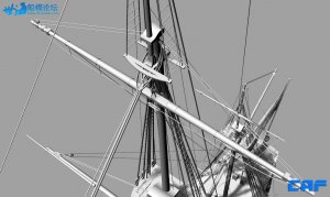
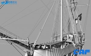
So if they designed the kit correctly according their 3D model, than my modelship should look like this at the end of my journey ...... let us see


Nice design work!!
hello Uwe, if your ship is ready, will it be that way?
greetings from Ostend
willy
greetings from Ostend
willy
Hi Uwe,
Yhere is a lot to find about the caf Salamandre on 4 H model. Guess you found these also there?
Yhere is a lot to find about the caf Salamandre on 4 H model. Guess you found these also there?
I am still not sure, if I will install the masts and rigging......the kit contents everything......but in wooden brownhello Uwe, if your ship is ready, will it be that way?
greetings from Ostend
willy
Correct, I found it on the 4hmodel web-pageHi Uwe,
Yhere is a lot to find about the caf Salamandre on 4 H model. Guess you found these also there?
I made some progress on the fashion pieces of the stern, hope not to get into the same problems like ADC, mentioned in his last post.
Unfortunately I forgot to make a photo of the elements before glueing together. In order to get the total thickness of 8mm of the pieces, CAF is preparing laser cut parts of 4mm which have to be glued together before sanding. With this technique you get the laser lines for beveling on both sides -> clever idea.
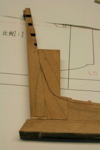
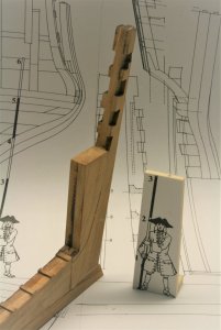
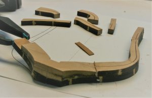
On the first photos you see the elements next to the sternpost from top view (on the left) and bottom view (on the right)
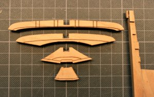
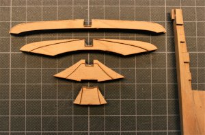
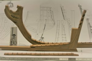
and the four elements at the stern......not prepared, only to get a feeling how it will look like
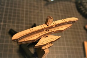
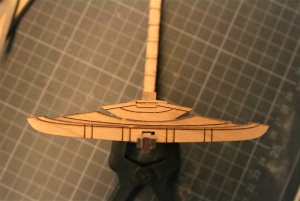
with this you get a feeling how the sanding of each individual element will fit together
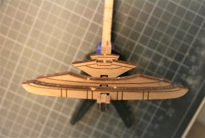
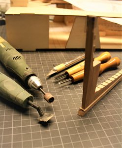
This time I used the Proxxon with small sanding drum for the beveling - before and after
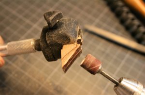
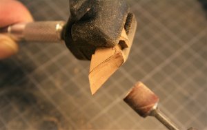
Three elements are pre-sanded today.......final sanding and adjustments at the stern with frame 45 in combination will be done later on
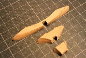
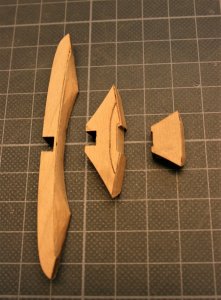
To be continued.......
Unfortunately I forgot to make a photo of the elements before glueing together. In order to get the total thickness of 8mm of the pieces, CAF is preparing laser cut parts of 4mm which have to be glued together before sanding. With this technique you get the laser lines for beveling on both sides -> clever idea.
On the first photos you see the elements next to the sternpost from top view (on the left) and bottom view (on the right)


and the four elements at the stern......not prepared, only to get a feeling how it will look like


with this you get a feeling how the sanding of each individual element will fit together

This time I used the Proxxon with small sanding drum for the beveling - before and after


Three elements are pre-sanded today.......final sanding and adjustments at the stern with frame 45 in combination will be done later on


To be continued.......
Coming back to the hawse pieces which I mentioned already in post #165 of this topic.
On each side there are 7 pieces which have to be prepared.
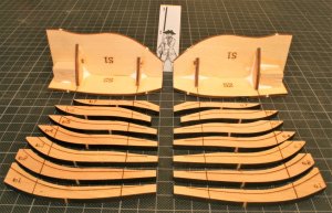
This photo you know aöready from the above mentioned post.
sanding according the kit prepared bearding lines
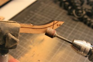
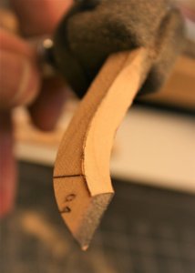
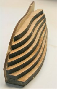
The seven pieces prepared with the inside sanding, so they fit into the jig
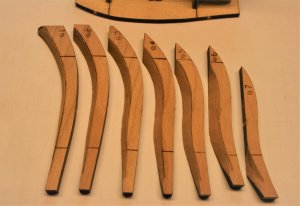
dry fitting of the seven pieces in the jig, stacked on top of each other
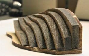
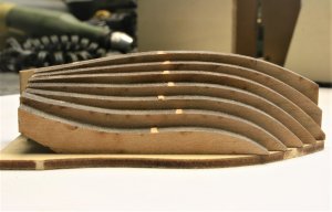
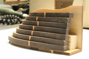
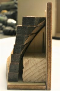
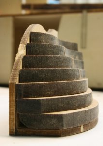
On each side there are 7 pieces which have to be prepared.

This photo you know aöready from the above mentioned post.
sanding according the kit prepared bearding lines


The seven pieces prepared with the inside sanding, so they fit into the jig

dry fitting of the seven pieces in the jig, stacked on top of each other


In order to see the result of the sanding works in post #236 "from inside" how the pieces are fiiting together, I decided to use some small parts of double sided adhesive tape between the pieces, so that the stacked seven seven pieces will stick together
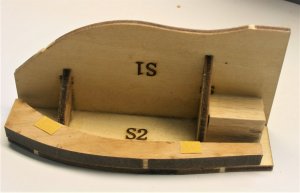
I repeated this on each level, so the elements keep the form
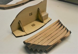
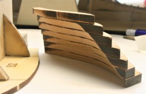
Here you can see the approximate location at the stem
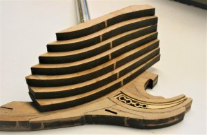
Tomorrow I plan to make the other package of the hawse pieces

I repeated this on each level, so the elements keep the form


Here you can see the approximate location at the stem

Tomorrow I plan to make the other package of the hawse pieces
Last edited:
Yesterday I posted three posts, but I have the feeling that most of you did realize only post two and three, but not the first one
..........It is only a check for me to make this topic as interesting as possible for you.......
Content of post #236 press to jump to post
Coming back to the hawse pieces which I mentioned already in post #165 of this topic.
On each side there are 7 pieces which have to be prepared.
View attachment 40944
This photo you know aöready from the above mentioned post.
sanding according the kit prepared bearding lines
View attachment 40945 View attachment 40946
The seven pieces prepared with the inside sanding, so they fit into the jig
View attachment 40947
dry fitting of the seven pieces in the jig, stacked on top of each other
View attachment 40948 View attachment 40949
View attachment 40951 View attachment 40950
View attachment 40952 View attachment 40953
Last edited:
Before I continue with the log, I want to say thank you to all for the feedbacks and also the big numbers of likes of my posts of this building log.
Thank you very much.....much appreciated
Now Back to the log:
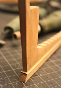
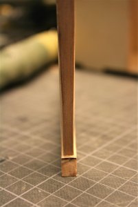
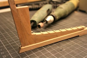
Further works on the frame No. 45 of the La Salamandre.
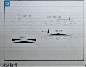
This is the drawing in the instruction and is showing the different working steps in order to get the two time 10° angle
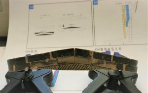
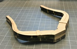
and this is the todays status of the assembled frame, in the background the sketch once more
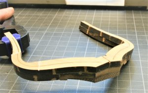
The area which is marked with the pencil has to be removed......some work for tomorrow
Many thanks for your interest ..... to be continued.....
Thank you very much.....much appreciated
Now Back to the log:
Further works on the frame No. 45 of the La Salamandre.
This is the drawing in the instruction and is showing the different working steps in order to get the two time 10° angle

and this is the todays status of the assembled frame, in the background the sketch once more

The area which is marked with the pencil has to be removed......some work for tomorrow


Many thanks for your interest ..... to be continued.....


