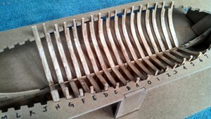
Lauck Street Shipyard AVS 1:32 Plank On Frame

Joined
Sep 5, 2017
Messages
1,689
Points
538

In 2015, Lauck Street Shipyard, owned by Bob Hunt, produced about 40 kits of an Armed Virginia Sloop plank-on-frame model. Bearing the fictional name Patrick Henry, this unique and amazing 1:32 scale model is quite rare in the community. I am the proud owner of Kit #002 and was one of Bob's students for many years along with several other members of SoS. I spent about 360 hours building this kit and an happy to share my 2015 log with you here. I will try to answer specific questions if I can but please remember it has been 5 years since I built the model. To my knowledge, mine was the first production kit to be completely built. DocBlake, another SoS member also has completed the Patrick Henry. His is absolutely stunning and modified with additional details not included in the kit. You can see Doc's Patrick Henry here on SoS as well. I'm sure he will be happy to help answer build questions too. So let's get to it.

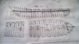
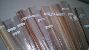
This kit comes with quality materials and excellent packaging. Offered in a variety of hardwoods, I choose the Redgum and Cherry option. I really like the way all the strip wood is organized by build topic versus type/size. This will make the build go much easier. There are 11 sheets of CNC cut parts, 22 individually labeled packages of strip wood, and a box of excellent 3D printed parts. To my knowledge, this might be the first kit to include 3D printed parts. There is also a special building jig and a display base. The CD's are packed full of documentation and build photos. 5 sheets of full sized plans and parts identifiers rounds out a box that weighs in at over 17 pounds. Here are a few pics:
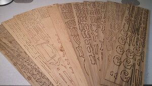
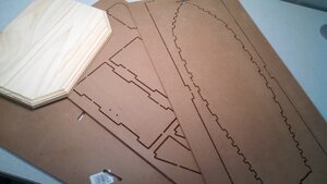
Parts1.jpgParts2.jpgParts3.jpgParts4.jpgParts5.jpg
 
Far, far, far away - way
People heard him say - say
I will find a way - way
There will come a day - day
Something will be done!!!
 
In 2015, Lauck Street Shipyard, owned by Bob Hunt, produced about 40 kits of an Armed Virginia Sloop plank-on-frame model. Bearing the fictional name Patrick Henry, this unique and amazing 1:32 scale model is quite rare in the community. I am the proud owner of Kit #002 and was one of Bob's students for many years along with several other members of SoS. I spent about 360 hours building this kit and an happy to share my 2015 log with you here. I will try to answer specific questions if I can but please remember it has been 5 years since I built the model. To my knowledge, mine was the first production kit to be completely built. DocBlake, another SoS member also has completed the Patrick Henry. His is absolutely stunning and modified with additional details not included in the kit. You can see Doc's Patrick Henry here on SoS as well. I'm sure he will be happy to help answer build questions too. So let's get to it.

This kit comes with quality materials and excellent packaging. Offered in a variety of hardwoods, I choose the Redgum and Cherry option. I really like the way all the strip wood is organized by build topic versus type/size. This will make the build go much easier. There are 11 sheets of CNC cut parts, 22 individually labeled packages of strip wood, and a box of excellent 3D printed parts. To my knowledge, this might be the first kit to include 3D printed parts. There is also a special building jig and a display base. The CD's are packed full of documentation and build photos. 5 sheets of full sized plans and parts identifiers rounds out a box that weighs in at over 17 pounds. Here are a few pics:
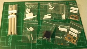
View attachment 159915View attachment 159916View attachment 159917View attachment 159918View attachment 159919
I bet is a lovely model when its built
 
REMEMBER THIS IS FROM 2015:

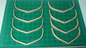
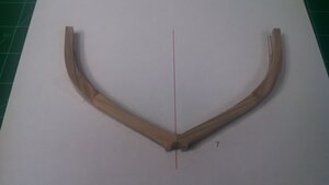
Here the first 8 frames have been glued up. A pretty straight forward procedure of cleaning up the parts and gluing them together on top of a printed template. I really like the sister-framing technique. Those of you planning to build this kit will need access to a color printer as there are quite a few sheets that have to be printed out. My first frame took nearly 2 hours to build. However, through repetition I now have the process down to 30 - 40 minute per frame. There are 9 parts for each frame. It's very nice working with hardwood versus the typical basswood of most kits. There will be lots of "firsts" for me with this kit... my first true plank on frame build, my first using hardwoods, my first Bob Hunt kit, and my first admiralty model.... very little rigging and minimal planking. This is gonna be fun!!

Frame3.jpg

27 Frames to do in total. I like to refine a repeatable process. Let me work the kinks out and share my steps to this process.
 
BULD LOG FROM 2015

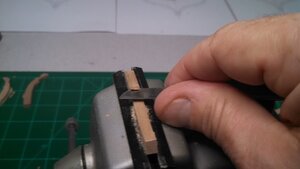
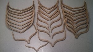
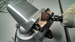
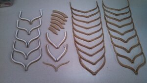
22 hours, 4 sanding sticks, 12 #10 blades, nearly 6 billets of redgum, 243 CNC parts, and 2 cut thumbs later - all 27 frames have been constructed. Things went a lot better and safer once I started clamping the parts into my Panavise.

My repeatable process was as follows:
1. Print the template and cut out the parts
2. Trim the tabs and lightly sand every surface of every part (some frames have 9 parts while others have 10)
3. Test lay-out the parts onto the template to get the orientation and best match for the parts
4. Apply double-sided tape to the template
5. Glue the pieces together on the template using the tape to keep the pieces in place
6. Place a book and some weight on top of the assembled frame. Allow the glue to dry for at least 30 minutes (I used
Weldbond)
7. Remove weights, remove frame from template, label the frame with a pencil and throw away the used template
8. Repeat 26 more times!!!

Frame1.jpg

Parts.jpg

Panavise.jpg

Frame2.jpg

Frames.jpg

Some additional tips:
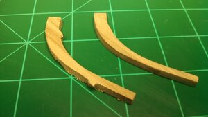
- I used several sharp #10 Xacto blades to carefully trim off the billet tabs from each part
- You might want to use some carving gloves or similar to prevent accidental nicks and cuts
- It's important to pay close attention to the grain of the wood when trimming off the tabs. It will cut easily in one
direction but not the other
- Use your sanding stick to lightly sand every surface of each part. Some of them have very minor chatter marks from
the CNC mill that need to be smoothed out to give the best appearance
So far, so good. No issues at all thus far. Smooth sailing. With that out of the way we can move on to beveling all the
frames inside and out

Total build duration so far: 22 hours
 
BUILD LOG FROM 2015 CONTINUES

Unlike most models, a lot of the frame beveling takes place off the model prior to assembly. This is possible due to the nature of the CNC design and the provided templates.

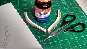
I used a set of lexan scissors left over from my radio controlled model days. They have curved blades which works nicely for cutting out the paper templates.
After I glue the templates, I label them with the frame number and an "F" to indicate for the forward side. I used Elmer's Rubber Cement to apply the templates to the frames. Works well but is a little messy. Luckily the cleanup is easy.
Frame Templates.jpg

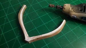
I primarily shaped each frame bevel with a Dremel tool and finished up with sanding sticks. It's important to keep the beveled surfaces flat to ensure the planks lay properly later on.
P2.jpg
First Bevel.jpg

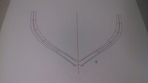
The bevel follows the green line on the front side and the red line on the stern side. I used a marker to darken the top of one of the frames so you can see how the template depicts the orientation of the bevel. It has become obvious to me now that much of the time spent on this model will be involving these frames. It makes
sense considering the frames are the center piece for this type of admiralty/craftsman style model. The time saved by not having rigging and minimal planking gets consumed on the frames.
Frame Bevel.jpg

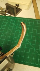
Some people may have trouble visualizing the frame beveling and I totally understand that feeling. I started with Frame 9 as it has the most bevel of any of the frames and is easier to visualize. After completing Frame 9, the rest of them go much easier. To confirm you are getting it right, you can hold the frame over the top of the jig drawing found on Plan Sheet 5. If you line it up and close one eye you can easily see that the angle of the shape you are beveling will match the drawing provided in the plan. I tried to show that in one of the pictures below. I get the beveling close with a dremel tool and then finish it off with a wooden sanding block refining it further and further with 3 different grits ending up at 220. Then I removed the template, cleaned up the glue and applied 3 coats of poly to each "edge" wiping it down with #00000 steel wool between coats.
Bevel Check.jpg


I have all the numbered and lettered frames assembled, beveled, and poly coated. The templates for the cant frames have been cut out and applied. I also got the hawse frames cut out, cleaned up and glued together. Per the practicum, I'm holding off on beveling the cant and hawse frames until later. With that said, Chapter 2 is now complete. Next, we will be moving forward with assembling the keel and jig. No problems so far - smooth sailing.

Total build duration so far: 41.5 hours
Frame update.jpg
 
BUILD LOG CONTINUES FROM 2015

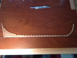
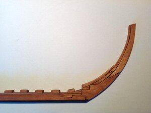
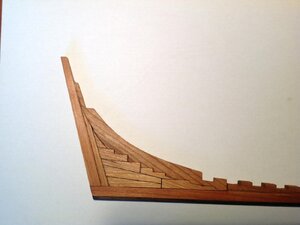
I've cut out and cleaned up the 17 parts that make up the keel. Make sure you lay your parts out against the plan drawing as I found the keel pieces to be about 1/8" too long. I easily shortened them up by sanding down the sister joint on both ends by 1/16". (Note: current and future production runs of this kit have that problem
corrected already). There is a lot more trimming and fitting that needs to be done before the parts can be glued together. Each of the frames has to be trim fitted and tested into the corresponding notches in the rising wood.

Keel1.jpg
 
Sorry, I don't have a better picture of this particular view. The parts were all CNC cut from the kit. All of the notches have to be custom filed/fitted and matched to their associated frame foot. That process will be shown, in detail, with better pictures in an upcoming post.
 
Thanks for the extra detail photos Dave. I am glad you had them as they help a lot.

BUILD LOG FROM 2015 CONTINUES

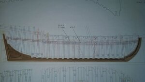
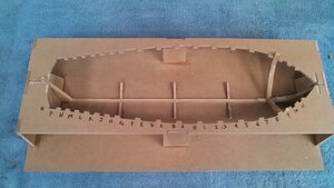
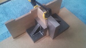
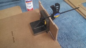
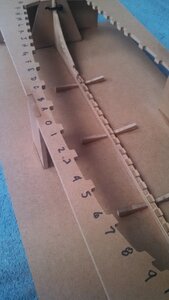
As a diversion, I decided to go ahead and assemble the jig. Basic straight forward construction per the practicum. I used a variety of machine squares and clamps to make sure everything was true. The top will not be glued on until the keel has been completed and installed. I simply have the main keel and frame 9 resting in the jig loosely to ensure everything looks lined up properly. I also annotated all the frame slots for easy reference later. The fit appears to be very nice at this point. Now I will go back to squaring up all those notches in the rising wood and get the keel glued together and installed. Continuing to move forward ....


Jig1.jpg

Jig2.jpg

Jig3.jpg

Jig Final.jpg
 
BUILD LOG CONTINUES FROM 2015

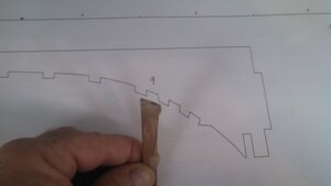
I spent a lot of time squaring up the notches in the rising wood and fitting each individual frame to it's designated notch. I used a sharp #10 xacto and a small file to trim away just a little at a time while testing the fit repeatedly as shown below. I also cut the rabbit bevels on the keel and rising wood. After completing all this work, just for the heck of it, I installed the keel, rising wood and most of the frames into the assembly jig just to get an idea of how it's all going to come together. Keep in mind that I haven't glued anything together yet. There is a lot of precision in this model - but you will need to take your time shaping each piece as a model of it's own to ensure the best results.

Total build duration so far: 56 hours

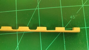
Rising wood. the notches on the left show the part prior to trimming. The notches on the right reflect the squaring work.
notch squaring.jpg

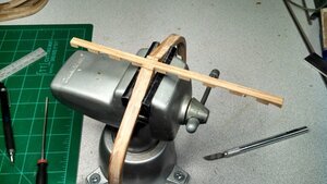
Clamp the frame in a vise and test fit the corresponding notch in the rising wood. Trim a little at a time until the fit is precise and snug
Notch Fitting.jpg

None of these pieces are glued together yet. Everything is just held together by parts fitment and the jig
Frame Test.jpg
 
2020 UPDATE

Interesting observation. The reason the rising wood notches have to be squared up is due to the nature of CNC machining. Since the CNC tool is round, the operation of cutting an inside 90 degree angle will always result in a curve that equals the radius of the bit. While this was true in 2015 and by and large a practice that remains true with most fabricators today, I have discovered a method from CNC furniture makers that allows for perfectly square fitment of parts of this nature.

I will demonstrate that for all of you at some point in the future.
Awesome development. This eliminates the biggest downside to CNC frames vs. laser cutting. CNC is better, by far.
 
Guys! I’m trying to decide whether to post my entire POF AVS build Log here on SOS. There’ll be a lot of repetition of Mike’s info, but different photos and some different techniques. Alternatively I could simply “hijack” Mike’s log on occasion when I have different info to offer. Full log or selective posting? Ideas?
 
Back
Top