Just go ahead and post a separate log,Guys! I’m trying to decide whether to post my entire POF AVS build Log here on SOS. There’ll be a lot of repetition of Mike’s info, but different photos and some different techniques. Alternatively I could simply “hijack” Mike’s log on occasion when I have different info to offer. Full log or selective posting? Ideas?
-

Win a Free Custom Engraved Brass Coin!!!
As a way to introduce our brass coins to the community, we will raffle off a free coin during the month of August. Follow link ABOVE for instructions for entering.
-

PRE-ORDER SHIPS IN SCALE TODAY!
The beloved Ships in Scale Magazine is back and charting a new course for 2026!
Discover new skills, new techniques, and new inspirations in every issue.
NOTE THAT OUR FIRST ISSUE WILL BE JAN/FEB 2026
You are using an out of date browser. It may not display this or other websites correctly.
You should upgrade or use an alternative browser.
You should upgrade or use an alternative browser.
Heck Dave, your build was so much better than mine with all the improvements you added.... perhaps a separate log would be better afterall.... Also, we might get readers confused if we mix them together...I’m trying to decide whether to post my entire POF AVS build Log here on SOS.
As a fairly new ship model builder, Doc, I would opt for the full log. I find the more details I see from you experienced guys the better my work becomes. You really do make a difference in the way we novices builds become and it's all positive. Thank you for offering.Guys! I’m trying to decide whether to post my entire POF AVS build Log here on SOS. There’ll be a lot of repetition of Mike’s info, but different photos and some different techniques. Alternatively I could simply “hijack” Mike’s log on occasion when I have different info to offer. Full log or selective posting? Ideas?
Awesome development. This eliminates the biggest downside to CNC frames vs. laser cutting. CNC is better, by far.
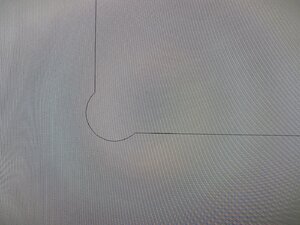
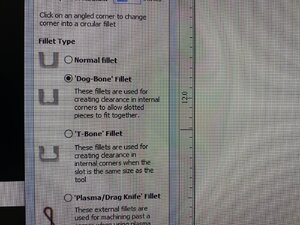
The technique is called a Dogbone Fillet. These fillets are used for creating clearance in internal corners when the slot is the same size as the tool. When machined in this manner, the parts will fit together squarely and the fillet will be hidden after assembly. Most professional CAD programs have this function.
I have attached a couple of pictures below. I greatly exaggerated the corner so you could get an idea of what I am describing.
I dont think I've ever seen a colabarative effort in building a model before, or anything else for that much. I think it would be really neat to see two accomplished shipwrights building the same ship and each offering their own ideas and suggestions to each other and everyone else.
Clair
Clair
Actually Clair this has already happened. Take a look at these build logs from a couple years ago where DocBlake, DonRobinson, and myself used Jeff Staudt's plans and basically designed an entire kit of a 17th Century Battle Station with some very new techniques.I dont think I've ever seen a colabarative effort in building a model before, or anything else for that much. I think it would be really neat to see two accomplished shipwrights building the same ship and each offering their own ideas and suggestions to each other and everyone else.
This was the original development work and the prototype that I built:
17th Century Battle Station
This project takes a bit of a different approach and uses some techniques not generally seen in the hobby. The Admiral and I own a home business making wedding and anniversary gifts. Our investment into this business allowed us to purchase both a CNC machine and a 60 watt laser. I have...
shipsofscale.com
Here is the build log of my second build of the production model. I have yet to complete it. LOL... :
Mike's 17th Century Battle Station
After 6 months of collaboration, development, prototyping, fabrication and mailing parts... I took the pile of what was left over and hopefully will be able to assemble my battle station from it. Notice I said "assemble". Although this is a scratch built wooden model, the way we fabricated...
shipsofscale.com
Here is DocBlake's build of the same model that he went on to win a contest award with.:
17th Century Battle Station - HMS Mordaunt, 1:32 - DocBlake
This will be my build log for a 17th century Royal Navy Battle Station. The station is loosely modeled after a 4th rate ship of the line, HMS Mordaunt, launched in 1681. It is based on the excellent plans drawn by Jeff Staudt, and the model itself is one of three produced in collaboration with...
shipsofscale.com
Here is DonRobinson's build of the same model that he has yet to finish:
Don's Battle Station
Hello All, I am finally getting around to starting this project and realise I have a long way to go to catch up to Mike and Dave. I thought to be a little different I would start with the carriages and give you a little different look at this model. The billet containing the the parts for the...
shipsofscale.com
Oh yes.... that is collaboration. Enjoy the read my friend!!!
MEANWHILE, BUILD LOG FROM 2015 CONTINUES
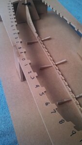
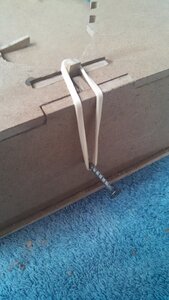
Completed assembly of the keel and installed it into the jig. Everything is looking nice and square. Don't forget to install the false keel prior to putting the assembly in the jig. For some added security I applied double-sided tape to the bottom of the jig where the keel lies. I also installed a screw into the front and rear of the jig and attached a rubber band to add a bit more security for the stern and stem posts. This is in addition to the zip tie provided in the kit. It might be a bit overkill but I wanted to be sure the keel remains solid in the jig. This completes Chapter 3. Moving on to framing the hull.
Total build time so far: 62 hours


Kurt Konrath
Kurt Konrath
Looking good so far. Glad to see this info.
BUILD LOG FROM 2015 CONTINUES
Only a couple hours work and I already have the first 5 pairs of frames installed with the associated filler pieces beveled and installed. Nothing is glued yet - I'm going to wait until I have most of the frames installed so that I can double and triple check the lay of the scuppers and oar sweeps to ensure they line up properly. The oar sweeps are milled directly into the filler block so placement is critical. I'll make minor adjustments if necessary and then come back around to glue everything in. The flow of the frames looks real nice at this point.
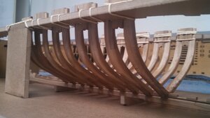
Only a couple hours work and I already have the first 5 pairs of frames installed with the associated filler pieces beveled and installed. Nothing is glued yet - I'm going to wait until I have most of the frames installed so that I can double and triple check the lay of the scuppers and oar sweeps to ensure they line up properly. The oar sweeps are milled directly into the filler block so placement is critical. I'll make minor adjustments if necessary and then come back around to glue everything in. The flow of the frames looks real nice at this point.

2015 BUILD LOG CONTINUES
Frame fitment testing continues. All the filler blocks are beveled. Slight adjustments to the foot of each frame to ensure they seat properly and line up with the rabbet. No glue yet....
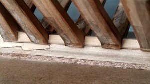
I've continued work by slowly refining the fit of the frames to the keel and jig. I now have all of the frames fitted with the exception of the two bow cant frames 10 & 11. I'm really pleased with the fit of the stern frames L, M, N, P. I recommend shaping and fitting these stern frames by slowly removing material a little at a time and testing the fit. Do this over and over and you will eventually get the fit pretty darned close. Final shaping can come later after the ship is removed from the jig and the final bevel sanding takes place. I also spent some time cleaning up the topside of each frame foot in preparation for fitting the keelson a bit further down the road. Nothing at this point has been glued in yet. I won't be gluing any of the frames until I have the basic fit and shape of the ship to where it needs to be. In the
meantime, the rubber bands work just fine to hold everything together. Patience is key here.... don't rush.... carefully sand/shape, test the fit, repeat. I've gone through all the frames at least twice now and plan another round before gluing.
Total build duration so far: 87 hours
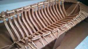
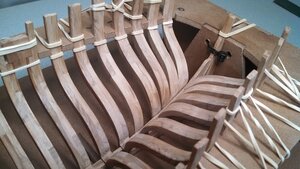
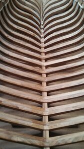
Frame fitment testing continues. All the filler blocks are beveled. Slight adjustments to the foot of each frame to ensure they seat properly and line up with the rabbet. No glue yet....

I've continued work by slowly refining the fit of the frames to the keel and jig. I now have all of the frames fitted with the exception of the two bow cant frames 10 & 11. I'm really pleased with the fit of the stern frames L, M, N, P. I recommend shaping and fitting these stern frames by slowly removing material a little at a time and testing the fit. Do this over and over and you will eventually get the fit pretty darned close. Final shaping can come later after the ship is removed from the jig and the final bevel sanding takes place. I also spent some time cleaning up the topside of each frame foot in preparation for fitting the keelson a bit further down the road. Nothing at this point has been glued in yet. I won't be gluing any of the frames until I have the basic fit and shape of the ship to where it needs to be. In the
meantime, the rubber bands work just fine to hold everything together. Patience is key here.... don't rush.... carefully sand/shape, test the fit, repeat. I've gone through all the frames at least twice now and plan another round before gluing.
Total build duration so far: 87 hours


FROM 2015
Cant Frames 10 and 11 are completed. These frames were very interesting to shape as they seem to not only curve with a taper but also twist slightly longitudinally. It took me right at an hour to shape each half of frame 10 and 1.5 hours for each half of frame 11. With all of the framing now complete, I will go back through and double check the alignment of all the filler blocks to ensure the sweep ports line up. I also plan to cut out the keelson parts and work their fitting against the foot of the frames and keel. Finally after all that is done, I will finish sand all the cant frames and give their inner edges 3 coats of poly like was done previously for the full frames. In case you are wondering - nope, I haven't glued anything yet.
Total build time so far: 92 hours
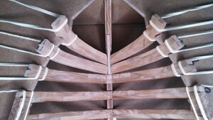

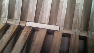
I spent a lot of time fine tuning the fit of the frames and their associated filler blocks. Make sure you pay close attention to how it's described in the practicum. I found the relationship between how deep the notch is cut on the bottom side of each frame foot (where it engages the rising wood) is critical to the resulting height and symmetry of the filler blocks. I ended up going through every frame/filler block several times making very minute adjustments to the fit ensuring that the sweep ports line up. I had to add a small bit of wood to the shorter side of several frames where the filler blocks sit. It's also important to make sure you have no gaps in how the filler blocks fit into the frames. This work was somewhat tedious as it took a lot of time with very little to show for it. But in the end, I'm hopeful that this attention to detail will make the resulting line of sweep ports look very nice on the finished model. After that was completed, I went back through and used a small metal file to carve the notches on the top side of each frame foot to ensure the keelson will fit later on. I cut out a piece of scrap wood the same width as the keelson to use as a measuring device for doing this. I also ended up cutting out the 5 pieces of the keelson and cleaned those parts up even though they don't actually get installed until chapter 6. Over several days, I also applied 3 coats of poly to the inner edges of all the half/cant frames rubbing them down with steel wool between coats.
With all that done, I have reached a milestone - LET THE GLUING BEGIN!!
Total build time so far: 103.5 hours
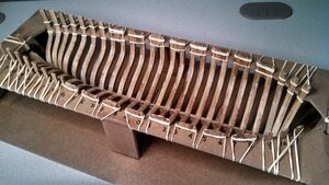
With all that done, I have reached a milestone - LET THE GLUING BEGIN!!
Total build time so far: 103.5 hours


BUILD LOG CONTINUES FROM 2015
The practicum shows a couple different ways to secure the frames as they are glued. I'm using a couple small clamps on each frame pair in addition to rubber bands. By lightly clamping the filler block above and below the jig will help to ensure a very square assembly. For the stern half frames, I started gluing at Frame K using a small clamp to hold them secure down on the deadwood. The bow cant frames held just fine using only rubber bands for gluing. It's pretty straight forward from here. Glue/clamp a frame pair, then wait an hour and move on to the next pair. Very satisfying to see this come together.
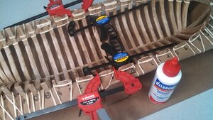
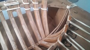
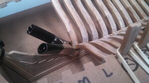
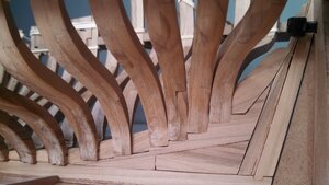
The practicum shows a couple different ways to secure the frames as they are glued. I'm using a couple small clamps on each frame pair in addition to rubber bands. By lightly clamping the filler block above and below the jig will help to ensure a very square assembly. For the stern half frames, I started gluing at Frame K using a small clamp to hold them secure down on the deadwood. The bow cant frames held just fine using only rubber bands for gluing. It's pretty straight forward from here. Glue/clamp a frame pair, then wait an hour and move on to the next pair. Very satisfying to see this come together.


Last edited:
Boy you got all that fitting together so good, looks great Mike!
Thanks Clair. Luckily I haven't gotten many questions since I built this model 5 years ago.Boy you got all that fitting together so good, looks great Mike!
CONTINUING BUILD LOG FROM 2015
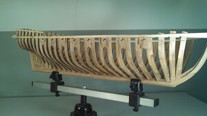
Out of the jig at last!! The first photo shows the comical situation when I realized that there would be no way to recover my rubber bands since the temporary battens had been installed. After much study, I came upon the best solution - I cut them. LOLOL.. Now it's on to those bow hawse frames.
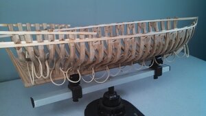
I couldn't save the rubber bands but at least the sweep ports lined up pretty nice.
Yup, me too. I am pretty sure DocBlake is going to repost his log but is just waiting for mine to get finished. Doc built his Patrick Henry right after mine and did an incredible job with additional details that will be reflected in his log.I am new in the forum but I vote for a full different log
Yeah but I bet DocBlake forgot to include the rubberized frame suspension supports!!!! 
Dave (DocBlake) never forgets frame suspension support, even the rubberizedYeah but I bet DocBlake forgot to include the rubberized frame suspension supports!!!
LOG CONTINUES FROM 2015
The bow hawse frames is probably the most difficult task for the whole model. My next several posts will describe the detailed process I used for shaping the hawse frames. Keep in mind, the photos will be of the left/port side. Let's start by cutting out the template for Hawse 1 and rubber cementing it to the inside/outer edge of the frame. Then, fit the frame into place on the step in the stem and slide it downward until it comes into contact with Frame 11. Make sure the frame stays square with the keel/stem. Read the captions that go along with the next several photos.
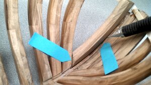
Remove material with your dremel where the orange arrow points in order to close the gap at the blue arrow
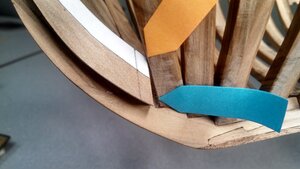
Remove a little wood at a time until the gap at the blue arrow is gone. You should be just about exactly where the reference mark on the template drawing falls
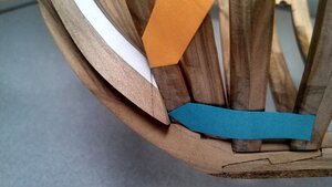
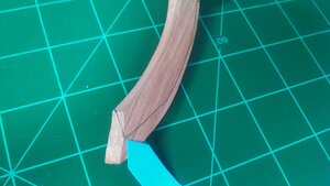
With the hawse frame in-place, use your pencil to mark the inside edge along the inner length and at the foot (see arrows)
These lines will define the inside bevel for the frame. The point at the blue arrow will be the inside bottom corner between the keel and Frame 11.
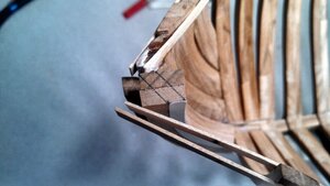
At the top of the hawse frame, mark a diagonal line from the outer edge of the template to the corner that rests in the stem-step. Mark a second line parallel to the first beginning at the inner edge/corner of the template. These two lines should be about 3/16" apart.
Now, mark a line that runs along the outside of the frame along the stem and at the foot as shown.
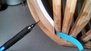
The combination of the paper template and the drawn lines will help you see exactly where the wood needs to be removed to obtain the desired shape. Note: It's the unshaded ares in these photos that get carved away. Now that we have that understanding, we can begin removing wood.
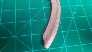
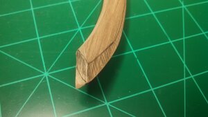
To begin shaping the hawse frame, I chose to start at the top as it's easier to visualize. The first objective is to shape the upper 1" of the frame so that the temporary battens will lie properly. Use your drawn reference lines as the guide - you might be surprised at how accurate they are.
Start with your #22 and carve away some of the more obvious excess wood. I usually focus on slicing away some of the corner edge.
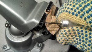
Use your dremel to sand the frame right down to the reference lines. Do this for both sides.
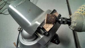
Place the hawse frame back into position and you will see that the temporary battens lie very nice against the area we just shaped
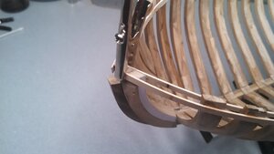
Now that we have the top of the frame shaped, we will move on to carve out the inner surface. You want to shape based on the plane defined by your drawn lines and the paper template. Ultimately, this plane needs to be flat width-wise but curved to follow the inner shape of the keel/bow/stem length-wise. See the photos and descriptions below for more info:
Start by using your #22 to trim away the excess wood down the length of the frame's inner surface
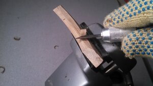
Use your dremel to finalize the shaping right down to the drawn reference line and the edge of the paper template. Use the drawing on the end of the frame as your guide to determine the proper angle
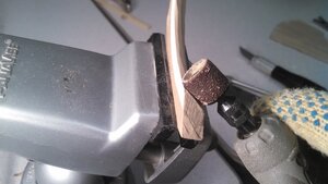
Fit the frame back into place and you can see how nicely the inner shape flows. It's only roughed in here and will be cleaned up later with a solid mini-sander (do not use a soft sanding stick). Now all we have left to do is the outer surface
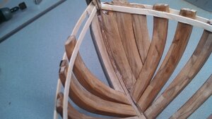
The outer side of the hawse frame is shaped exactly the same way using the edge of the paper template and the line we drew as a guide. Carve away some of the excess wood with your #22 and then do the final shaping with your dremel tool. Once the shaping is done you can see how nicely the hawse frame fits into its location and how its shape flows into the general outline of the ship. Keep in mind the rabbet has not yet been cut in this photo.
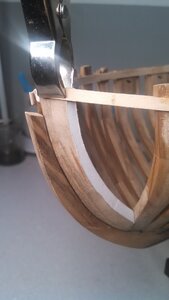
The second and third hawse frames are shaped using the same method as the first. Although no paper template is provided for the third hawse frame you should have no trouble determining where to draw the lines for its shaping once you have experience for the first two.
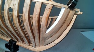
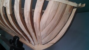
The bow hawse frames is probably the most difficult task for the whole model. My next several posts will describe the detailed process I used for shaping the hawse frames. Keep in mind, the photos will be of the left/port side. Let's start by cutting out the template for Hawse 1 and rubber cementing it to the inside/outer edge of the frame. Then, fit the frame into place on the step in the stem and slide it downward until it comes into contact with Frame 11. Make sure the frame stays square with the keel/stem. Read the captions that go along with the next several photos.
Remove material with your dremel where the orange arrow points in order to close the gap at the blue arrow

Remove a little wood at a time until the gap at the blue arrow is gone. You should be just about exactly where the reference mark on the template drawing falls

With the hawse frame in-place, use your pencil to mark the inside edge along the inner length and at the foot (see arrows)

These lines will define the inside bevel for the frame. The point at the blue arrow will be the inside bottom corner between the keel and Frame 11.

At the top of the hawse frame, mark a diagonal line from the outer edge of the template to the corner that rests in the stem-step. Mark a second line parallel to the first beginning at the inner edge/corner of the template. These two lines should be about 3/16" apart.

Now, mark a line that runs along the outside of the frame along the stem and at the foot as shown.

The combination of the paper template and the drawn lines will help you see exactly where the wood needs to be removed to obtain the desired shape. Note: It's the unshaded ares in these photos that get carved away. Now that we have that understanding, we can begin removing wood.


To begin shaping the hawse frame, I chose to start at the top as it's easier to visualize. The first objective is to shape the upper 1" of the frame so that the temporary battens will lie properly. Use your drawn reference lines as the guide - you might be surprised at how accurate they are.
Start with your #22 and carve away some of the more obvious excess wood. I usually focus on slicing away some of the corner edge.

Use your dremel to sand the frame right down to the reference lines. Do this for both sides.

Place the hawse frame back into position and you will see that the temporary battens lie very nice against the area we just shaped

Now that we have the top of the frame shaped, we will move on to carve out the inner surface. You want to shape based on the plane defined by your drawn lines and the paper template. Ultimately, this plane needs to be flat width-wise but curved to follow the inner shape of the keel/bow/stem length-wise. See the photos and descriptions below for more info:
Start by using your #22 to trim away the excess wood down the length of the frame's inner surface

Use your dremel to finalize the shaping right down to the drawn reference line and the edge of the paper template. Use the drawing on the end of the frame as your guide to determine the proper angle

Fit the frame back into place and you can see how nicely the inner shape flows. It's only roughed in here and will be cleaned up later with a solid mini-sander (do not use a soft sanding stick). Now all we have left to do is the outer surface

The outer side of the hawse frame is shaped exactly the same way using the edge of the paper template and the line we drew as a guide. Carve away some of the excess wood with your #22 and then do the final shaping with your dremel tool. Once the shaping is done you can see how nicely the hawse frame fits into its location and how its shape flows into the general outline of the ship. Keep in mind the rabbet has not yet been cut in this photo.

The second and third hawse frames are shaped using the same method as the first. Although no paper template is provided for the third hawse frame you should have no trouble determining where to draw the lines for its shaping once you have experience for the first two.


