I completely agree with Brian - looking really goodHi Mike,
just catching up on your build log. Looking good my friend.
-

Win a Free Custom Engraved Brass Coin!!!
As a way to introduce our brass coins to the community, we will raffle off a free coin during the month of August. Follow link ABOVE for instructions for entering.
-

PRE-ORDER SHIPS IN SCALE TODAY!
The beloved Ships in Scale Magazine is back and charting a new course for 2026!
Discover new skills, new techniques, and new inspirations in every issue.
NOTE THAT OUR FIRST ISSUE WILL BE JAN/FEB 2026
You are using an out of date browser. It may not display this or other websites correctly.
You should upgrade or use an alternative browser.
You should upgrade or use an alternative browser.
Thank you all for the very kind comments.
LET US CONTINUE FROM 2015
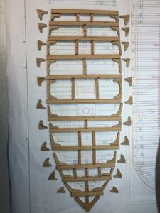
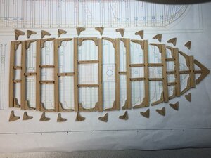
Learning all about main beams, carlings, ledges, lodging knees, and hanging knees. More than 128 parts will go into the main deck framing, most of them pictured here. Lots of cutting, trimming, sanding and shaping.
Total build duration so far: 201.5 hours
I can't seem to stop working on this model. I got the main deck clamps installed and the forward portion of the main deck assembled. Be sure to read the practicum for this procedure very closely. Most importantly, you will want to shape and fit each and every part "on the model". If you assemble it over the plans its likely to not fit very well. Very slight sanding and shaping of individual parts will fine tune the fit. From here, I will construct the deck towards the stern while detailing out the lower deck along the way. We still have a long way to go ...
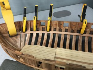
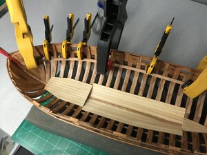
Take your time here - follow the practicum and try to be as precise as you can.
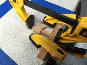
Each part is it's own model
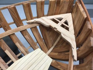
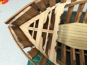
Nice fit. No glue yet.
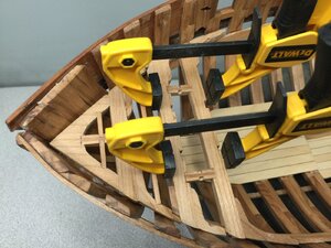
LET US CONTINUE FROM 2015
Learning all about main beams, carlings, ledges, lodging knees, and hanging knees. More than 128 parts will go into the main deck framing, most of them pictured here. Lots of cutting, trimming, sanding and shaping.
Total build duration so far: 201.5 hours

I can't seem to stop working on this model. I got the main deck clamps installed and the forward portion of the main deck assembled. Be sure to read the practicum for this procedure very closely. Most importantly, you will want to shape and fit each and every part "on the model". If you assemble it over the plans its likely to not fit very well. Very slight sanding and shaping of individual parts will fine tune the fit. From here, I will construct the deck towards the stern while detailing out the lower deck along the way. We still have a long way to go ...


Take your time here - follow the practicum and try to be as precise as you can.

Each part is it's own model


Nice fit. No glue yet.

LOG CONTINUES FROM 2015
Here I have completed assembly of the main deck up to beam 5. This is a long process and there are many parts involved. Each part has to be custom shaped with lot's of careful test fitting. The practicum explains the process very well but it still took me a while to get my head wrapped around it. Be sure to pay close attention to the many various relationships of the parts. I found myself working 1 - 2 beams ahead of where I was gluing. I didn't do a perfect job but I think it will be adequate as the build progresses. From here, I will need to paint and install the ship's oven and then build a bulkhead that will close off the forward area.
Total build duration so far: 214 hours
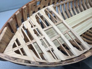
More than 80 individually cut and shaped parts make up the forward portion of the main deck!!
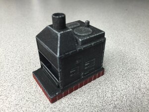
Look at this 3D printed jewel!! I resisted the temptation to super detail the stove as it won't be that easy to see below the deck. All I did was paint it and give it a light dry brushing. This is the first time I have ever seen a ship's stove included in a kit (Edited: as of 2015). What do you all think?
Here I have completed assembly of the main deck up to beam 5. This is a long process and there are many parts involved. Each part has to be custom shaped with lot's of careful test fitting. The practicum explains the process very well but it still took me a while to get my head wrapped around it. Be sure to pay close attention to the many various relationships of the parts. I found myself working 1 - 2 beams ahead of where I was gluing. I didn't do a perfect job but I think it will be adequate as the build progresses. From here, I will need to paint and install the ship's oven and then build a bulkhead that will close off the forward area.
Total build duration so far: 214 hours

More than 80 individually cut and shaped parts make up the forward portion of the main deck!!

Look at this 3D printed jewel!! I resisted the temptation to super detail the stove as it won't be that easy to see below the deck. All I did was paint it and give it a light dry brushing. This is the first time I have ever seen a ship's stove included in a kit (Edited: as of 2015). What do you all think?

Obviously new technology works great for us, no doubt, and this little stove is not an exception, nicely made and great painting job to make it used!!
3D printing..., CNC timber processing\carvings, Laser cutting... Hmmm...what next?? How those shipwrights make their models without all this technology?
3D printing..., CNC timber processing\carvings, Laser cutting... Hmmm...what next?? How those shipwrights make their models without all this technology?
Very, very skillfully.... very, very slowly .... and ultimately NOT with the same level of detail as what is being introduced today. Remember the simple 3D printed stove above was from 2015... 5 years ago.... Things have come along way even since then!!How those shipwrights make their models without all this technology?
BUILD LOG CONTINUES FROM 2015 - I GOTTA KEEP GOING BEFORE @DocBlake CATCHES ME AND CAUSES A GLITCH IN THE MATRIX!!
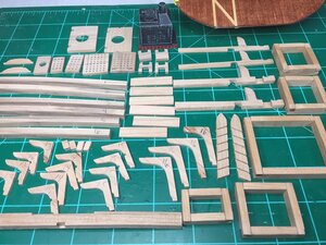
Been spending time cutting out parts, cleaning them up and fabricating various small sub assemblies that will be required as the main deck gets further built out. I've painted the ship's stove, built and stained the forward bulkhead, and assembled the 5 hatch combings. I've also got parts for the bitts, ladder and the quarter deck beams and lodging knees ready. All the parts and assemblies are straight forward. I'm basically getting all the parts I need to finish Chapter 7 ready. Have I mentioned that there are a LOT of parts on this model?
Total build duration so far: 228.5 hours

CONTINUING FROM 2015
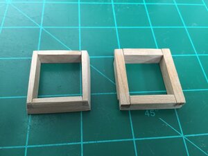
The practicum calls for the hatch combings to be cut at an angle as seen in the first picture on the left compared to the original on the right. I'd like to share my method for doing this but I should warn that if you are not very adept at the use of power tools with very fine control then you may want to practice this on scrap wood first. Of course this tapering can be done by hand but my way completes the task in under 5 minutes. I used 120 grit fine paper on my 5" disc sander. The finer the grit, the more control you will have as the material won't be removed as fast.
Tapered hatch combing on the left - original on the right
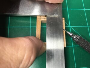
Mark a centered line on the tops of each side
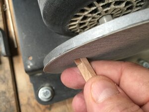
Carefully sand the top edge down to the reference line. Repeat this for all 4 sides
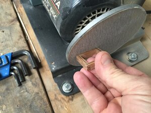
Turn combing on edge and carefully sand the angle to the bottom of the frame. You will need to do this twice on each corner. For the larger combings be sure you apply even pressure across the entire length of the combing frame.
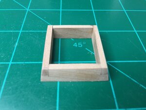
Completed - looks pretty good
The practicum calls for the hatch combings to be cut at an angle as seen in the first picture on the left compared to the original on the right. I'd like to share my method for doing this but I should warn that if you are not very adept at the use of power tools with very fine control then you may want to practice this on scrap wood first. Of course this tapering can be done by hand but my way completes the task in under 5 minutes. I used 120 grit fine paper on my 5" disc sander. The finer the grit, the more control you will have as the material won't be removed as fast.
Tapered hatch combing on the left - original on the right

Mark a centered line on the tops of each side

Carefully sand the top edge down to the reference line. Repeat this for all 4 sides

Turn combing on edge and carefully sand the angle to the bottom of the frame. You will need to do this twice on each corner. For the larger combings be sure you apply even pressure across the entire length of the combing frame.

Completed - looks pretty good

Nice work on the hatch coamings, Mike! You see so many models with butt joints and no beveling of the hatch coamings. This is how they were built. In general, the half-lap joints were oriented so when viewed from above, the sides of the coaming that run the full dimension of the hatch are oriented transversely, athwart the midline, as Mike shows in his photo
butt joints and no beveling
See, this is why I love this forum......People can say Butt Joints!!!
Thank you both for that though, I didnt know they were beveled or how they were joined. I always asumed at 45 degrees like a picture frame.
BUILD LOG CONTINUES FROM SOMEWHERE IN THE PAST
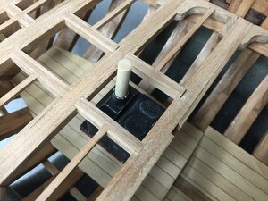
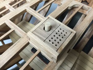
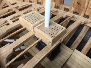
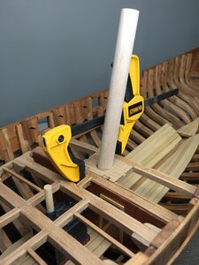
The kit provides a nifty means to ensure the placement of the stove below deck aligns with the chimney hole in the hatch. A small wooden dowel is placed into the stove chimney. Then the hatch can be centered on the wooden dowel. Finally the plastic tube for the actual chimney can be inserted through the hole in the hatch right over the dowel. Later the chimney tube will be cut to length and painted black.
Stepping the mast!
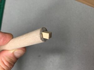
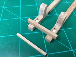
Main bitt fit test... lots of work in this area. Be careful on the smaller CNC parts. I sanded too much off the cross bar for the main bitts on Billet 11 (Part MB). It ended up too small so I easily fixed that by cutting a new part from the "Gunport framing" stripwood. And no, my sheaves do not operate - afterall, this is an admiralty model. I sliced the sheave pulleys from 3/16" dowel
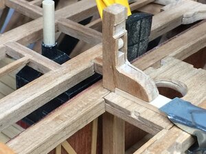
Adjust the fit so that it will ride on top of the future planking
The kit provides a nifty means to ensure the placement of the stove below deck aligns with the chimney hole in the hatch. A small wooden dowel is placed into the stove chimney. Then the hatch can be centered on the wooden dowel. Finally the plastic tube for the actual chimney can be inserted through the hole in the hatch right over the dowel. Later the chimney tube will be cut to length and painted black.


Stepping the mast!


Main bitt fit test... lots of work in this area. Be careful on the smaller CNC parts. I sanded too much off the cross bar for the main bitts on Billet 11 (Part MB). It ended up too small so I easily fixed that by cutting a new part from the "Gunport framing" stripwood. And no, my sheaves do not operate - afterall, this is an admiralty model. I sliced the sheave pulleys from 3/16" dowel

Adjust the fit so that it will ride on top of the future planking

Last edited:
Kurt Konrath
Kurt Konrath
No center notch in pulleys to keep ropes centered, or is this a different style of pully?
Admiralty style....or is this a different style of pully
Kurt Konrath
Kurt Konrath
OK, I have seen some with pulleys with grooves and no ropes, didn't know the Admiralty Style had its own pully style.
It was said in jest... Admiralty style models typically focus more on showing off the actual framing structure of the ship than details. So for this reason a lot of the more detailed parts (like pulley grooves) might be left plain. Really its just an excuse, HAHAHA. I built my model straight-out-of-the-box... the way Bob Hunt designed it. You will see on @DocBlake version he put in a lot of extra effort and details!!didn't know the Admiralty Style had its own pully style.
Kurt Konrath
Kurt Konrath
OK, Not an issue, just learning things from old masters!
The riding bitt was far more complicated than it looks. There were a total of 11 individual parts. Simulating the sheaves drove thee part count up!
- Joined
- Jul 9, 2019
- Messages
- 497
- Points
- 323

Sounds like I'm switchign to Weldbond...One of the great advantages of Weldbond. Also, you can scrape it off of wood easily if you plan to use stain. Dried Titebond will NOT allow stain to penetrate. And you can’t get it out of the wood pores once dry.
ABOUT 5 YEARS AGO
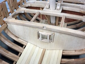
Make sure to note that Bulkhead 2 is fitted under the beam, while Bulkhead 1 was fitted to the face of it's beam. Here is Bulkhead 2 built, planked, and with the light room window framed up, ready for staining. The main deck is now built out about halfway. No issues at all except that I can't seem to stop ...
Bulkhead 2 fits under Beam 8. Use the practicum method of cutting the template in half for more precise fitment
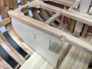
Planked and fitted. Later, clear plastic will be added to the light room window to simulate the glass panes. A small hatch will also be added
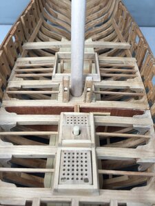
None of the furniture is glued down
Make sure to note that Bulkhead 2 is fitted under the beam, while Bulkhead 1 was fitted to the face of it's beam. Here is Bulkhead 2 built, planked, and with the light room window framed up, ready for staining. The main deck is now built out about halfway. No issues at all except that I can't seem to stop ...
Bulkhead 2 fits under Beam 8. Use the practicum method of cutting the template in half for more precise fitment

Planked and fitted. Later, clear plastic will be added to the light room window to simulate the glass panes. A small hatch will also be added

None of the furniture is glued down

A LONG TIME AGO BUT NOT SO FAR AWAY
Bulkhead 2 has been completed and installed. While I waited a day for the stain to dry I sanded, trimmed, and prepped the remaining beam parts for the main deck. There are a total of 5 bulkheads to build with each being slightly different.
Total build duration so far: 252.5 hours
Note the window "glass". The simple hatch framing is replicated on both sides of the bulkhead. I used a mahogany stain just like Bob did in the practicum
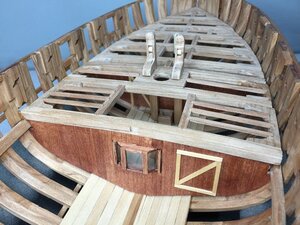
Main Beam 10 installed, Bulkhead 3 fitted and ready for staining.
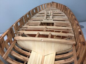
With Bulkhead 3 stained and installed, we move on to Bulkhead 4 and the end of the main deck.
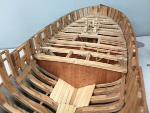
Bulkhead 4 fits against the aft side of Main Beam 12 and is ready for staining. It will have a door in the center.
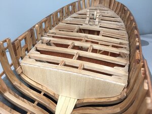
Bulkhead 2 has been completed and installed. While I waited a day for the stain to dry I sanded, trimmed, and prepped the remaining beam parts for the main deck. There are a total of 5 bulkheads to build with each being slightly different.
Total build duration so far: 252.5 hours
Note the window "glass". The simple hatch framing is replicated on both sides of the bulkhead. I used a mahogany stain just like Bob did in the practicum

Main Beam 10 installed, Bulkhead 3 fitted and ready for staining.

With Bulkhead 3 stained and installed, we move on to Bulkhead 4 and the end of the main deck.

Bulkhead 4 fits against the aft side of Main Beam 12 and is ready for staining. It will have a door in the center.


 !! Amazing !!