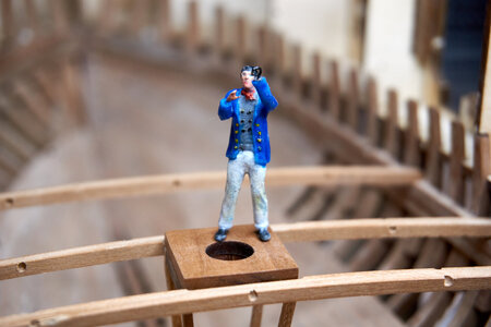
Le Coureur 1776, CAF model 1:48 by Poul

nice job Poul.
Enjoy your family!
As for the "window" I am also of the idea that it is advisable to try to show as much as possible what is inside
I have kept as a reference the last board that reaches the edge of the ballast compartment which runs very straight from bow to stern .. and this for me represents the maximum possible opening. (Seeing the ballast from below would not add much )
Trying to dry fit the floor of the various sections of the hull it seems to me that in this way one should see almost everything from the outside, or at least have a precise idea of it.
 
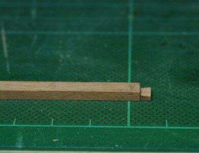
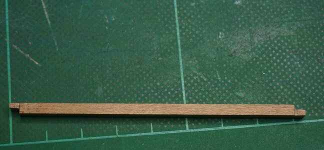
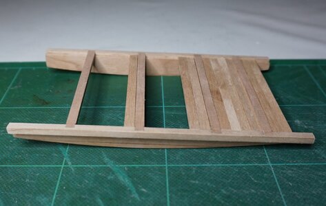
To get a pause form the inside planking I started today on the dog sledge aka ballast platform. I cut all the dovetail tennons and mortises with a scalpel and I dry fit one by one and marked them with numbers:
DSC01806.JPG

When I dry fitted the dovetails one by one I thought they fit reasonably okay but when I glued all the parts together I could not get the last beam to fit :confused:
When Forest Gump was asked if he was stupid he answered “Stupid is as stupid does”, meaning that a person should be judged by his actions, not his appearance. Well, judged by my action I'm indeed not the sharpest knife in the drawer:
DSC01807.JPG
:rolleyes::rolleyes::rolleyes:

Luckily there was enough wood leftover in te plate to make a new beam from scratch and finish the dog sledge:
DSC01804.JPG
 
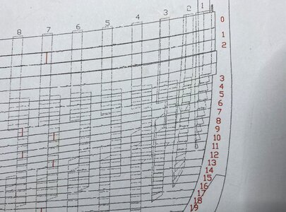
Hi Poul..........I am in the process of installing the forward rail clamps and have a question , if I may. How did you determine the placement ie: height
of frames #2 and #3. I would think this important as to the shape and flow of the planking afterward.

Merci jb
 
Hi JB,
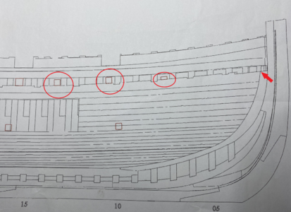
The height of the forward deck clamp is determined with 3 sticks, 1 stick 2x4 mm and 2 sticks 4x4 mm. Besides, the top of the keelson can help :
IMG_1050.png
BTW, 2 sticks of 2x4 mm can also be used as one 4x4 when 4 sticks are not enough. Also a 2x4 stick can be used in a few of the holes for the lower deck markings which are not really square and if a frame is in the way.

The location of frame 2 and 3 has to be determined from the drawing. Note that these frames are not vertical.
IMG_1051.JPG
 
Last edited:
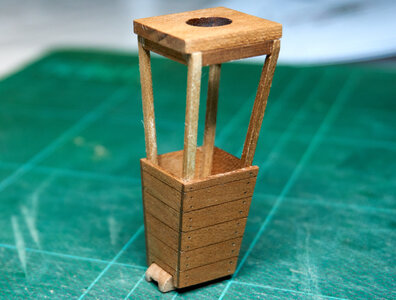
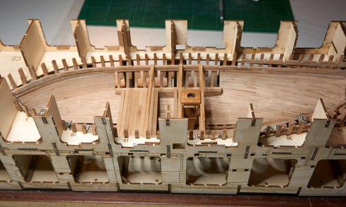
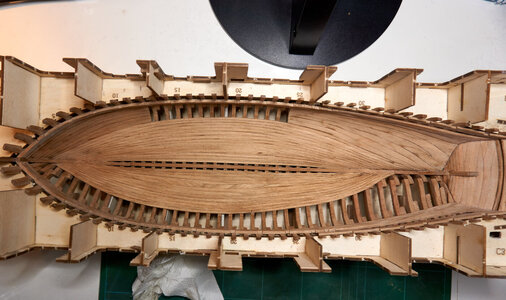
I finally finished at least the starboard side of the inner planking. It did not became as good as I would have liked though. Sure hope I'm getting better at this. Still missing some planks at the port side but once again I needed a little variation with something easier than the grueling planking work so I made the mast well
DSC01811_1.jpg
DSC01815_1.jpg
 
I finally finished at least the starboard side of the inner planking. It did not became as good as I would have liked though. Sure hope I'm getting better at this. Still missing some planks at the port side but once again I needed a little variation with something easier than the grueling planking work so I made the mast well
View attachment 204752
View attachment 204753
Nice and accurate work Poul, looking really good.
 
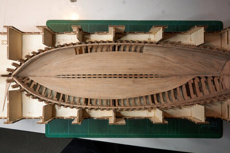
Finally done with the inside planking
DSC01818_1.jpg


I kinda thought Le Coureur was going to be a very fast ship as it seems to be a rig with getaway power, but no wonder this ship is anyway bound to be captured by HMS Alert.
Not only is the ship builder a miserable dilettante, a klutzy goon and a clogfoot talentless amateur, as Capitaine Archibald Haddock would say. The crew that was sent for the ship is certainly not much better. It appears that several of the officers are old disabled veterans with hooks instead of hands.
DSC01821_1.jpg
 
Looking very good my friend - Congratulation for the finishing of one important working step!

and Jaques Denys, the shipwright who built the original in Dunkerque, Flanders would be very proud of this shipyard model


And what will come now? Interieur or outside planking?
 
Many thanks for the comments and likes guys :) I was really not happy with my planking work. For example, a few of the planks broke for me :oops: And of course this happens 5-7 mm from the aft end where the plank has to be bended in 2 directions and the plank is very thin and the grains are in a total wrong direction :rolleyes:. I started the port side from the keel and I wish I had started from the top also on the port side. It did not become a mirror of the starboard side. .

Anyway, a bit of cleaning and sanding made it appear better though. This and not at least your comments made me feel kinda content.

What is the next step? Well, I think had enough planking for the time being :D Hence I'll make at least a few the bulkheads etc while I slowly regain courage enough to start on the clinker planking.
DSC01823_1.jpg
 
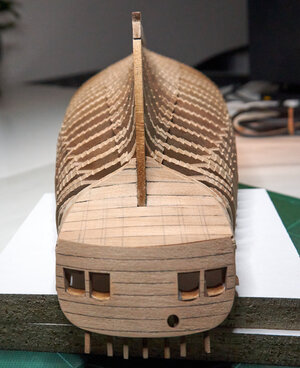
I could not resist to take the ship out of the jig. Gosh, it felt jolly good to see the lines outside the jig :D I managed to take it out without damaging the jig too much so it could be put back again. However, I decided to plank the lower part of the stern so at last the jig went into the trash bin.
DSC01835.jpg
The lowest planks are not sanded yet as the glue is not dry.

Now I have a lot of questions to my SoS friends
1) I assume the empty space between the 2 upper and lower deck clamps inside the ship should be planked. However, I don't see anything about it in the manual (maybe I can't see the forest for trees). Should this plank be made from scratch or . . .?

2) Also I don't find any numbers or reference in the manual to the small brass rings and eyelets on the hatches for the small decks in the hold (maybe also here I can't see the forest for trees). Are these supposed to be made from scratch? (the eyelets seem to much smaller than the eyelets on the hatches on the weather deck)

3) According to figure 19 in manual 2 the cargo hold pillars have to be installed before the platform. I think I have to it the other way around. It says pillars but the drawing shows only one. Is there more than 1 pillar? It is not on the plan and the drawing in the manual does not show the details. I know there should be some notches on the corners but I don't know the purpose of these, how many corners, how long they should be, which directions etc. Does any of you have any knowledge or information about this

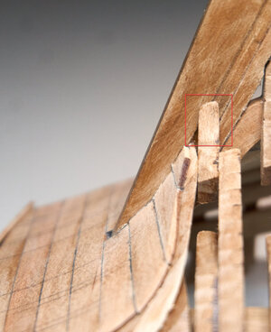
4) The bottom of my frame 37 is covering the rabbet on the stern post. I don't understand why as I think it is in the right position? Looking at the plans it seems the lowest part of this frame is not visible at all. Strange! I guess it has to be modified so that it fades out into the rabbet?
DSC01838.jpg
5) According to the manual the sides of the ship should be planked before the transom / upper part of the stern. Is there any good reason for that or would it perhaps be wiser to do the transom first?
 
Back
Top