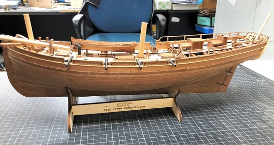
I think that this would be a good idea - it is really hard to see anything later onI'm wondering if anyone has attempted to cut out some of the exposed frames to make the interior easier to view from the side?
-

Win a Free Custom Engraved Brass Coin!!!
As a way to introduce our brass coins to the community, we will raffle off a free coin during the month of August. Follow link ABOVE for instructions for entering.
-

PRE-ORDER SHIPS IN SCALE TODAY!
The beloved Ships in Scale Magazine is back and charting a new course for 2026!
Discover new skills, new techniques, and new inspirations in every issue.
NOTE THAT OUR FIRST ISSUE WILL BE JAN/FEB 2026
- Home
- Forums
- Ships of Scale Group Builds and Projects
- Le Coureur 1776 1:48 PoF Group Build
- Le Coureur 1776 1:48 Group Build Logs
You are using an out of date browser. It may not display this or other websites correctly.
You should upgrade or use an alternative browser.
You should upgrade or use an alternative browser.
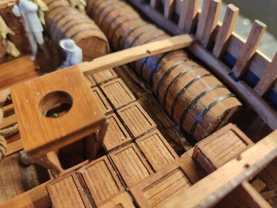
Finally finished the barrels. This was my least favorite job as working with the rings and superglue was very messy. But it's finally done.
I also made a small stack of firewood for the stoves from the Admiral's boxwood bush. It's been warm here so the twigs are already turning green but that will resolve itself with time.
Nothing glued in place yet, everything is still loose as I try to figure out where everything will end up.
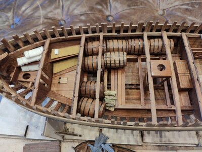
I also made a small stack of firewood for the stoves from the Admiral's boxwood bush. It's been warm here so the twigs are already turning green but that will resolve itself with time.
Nothing glued in place yet, everything is still loose as I try to figure out where everything will end up.

I completed the large boxes included with the box and barrel kit that CAF includes with the model. These were quite difficult as the outer frames are extremely fragile. I then discovered a trick that helped a lot. If you place a small drop of superglue on the frames at the weak points, it reinforces the wood and renders it strong enough to safely cut with a sharp blade.
Finished up the small boxes today. Photo below shows how I reinforce the fragile parts of the precut pieces using superglue. I should have also reinforced the center of the pieces as a number of them broke while cutting them loose.
The glue is generally not visible after applying tung oil but it sands off as well.
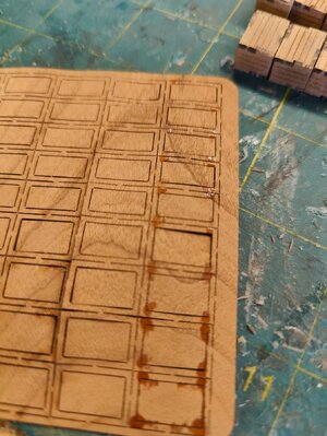
The glue is generally not visible after applying tung oil but it sands off as well.

Your hold is looking very good - I like the way of presenting very much
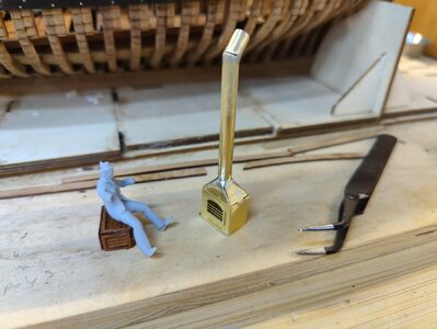
Decided to try my hand at soldering the aft brass oven. Pretty ugly but it worked! Not easy at all... I think I need an extra hand tool but I managed.
I later primed and painted it, which did a nice job of filling up the seams so they are not visible.
It appears to me that the plans have reversed the direction of the chimney so that it points fore. I would think this has to be incorrect, as it would not be good to have a strong wind blowing down into your oven while you're standing in front of it.
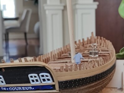


If it is too much work - you can every time say, that the ship is in moment moored in a harbour, than the turned the chimney according the wind direction.... 
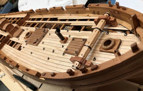
I've begun work on the deck (a milestone!). In thinking about the waterways, I really don't like how the kit represents them. I will probably follow Uwek's lead and attempt to fabricate some better ones from Swiss pear. Both his and Adi's models show wonderful examples of this.
While I have a decent set of tools, I'm not sure how to go about making them though. I'll obviously rip some square strips from a plank (4mm square). But I'm not sure how to go about cutting off a 45 degree angle through the sides. Is it as simple as carving the bulk away with a knife and sanding it flat? Or would it be better to use a Proxxon table saw for this (I think I can tilt my blade 45 degrees but I haven't actually used it yet as I've been waiting for an opportunity like this to arise!)
Photo below shows the deck which is simply laid in place at this point. I used Ecoline black to represent the pitch between the planks and it works incredibly well. Deck is not sanded yet, of course.

@Uwek - I am looking over your log and it does not appear that your waterways are cut at a 45 degree angle. Do you know what angle you used? Also I am wondering if you started with straight 4mm x 4mm lengths of wood and then bent them to fit, or if you first cut the waterways to fit the sides (ie: no bending)?
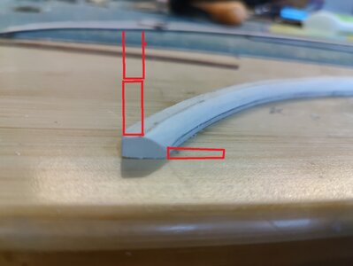
I decided to make an attempt at fabricating a waterway using inexpensive basewood. No harm in trying!
It was immediately apparent that a piece of this thickness would be difficult to bend. So I began by tracing the pattern of the original waterway onto the wood. I cut the piece out (roughly) using a coping saw. Then I sprayed a bit of adhesive on the piece and stuck the original waterway on top of it. Finally, I removed most of the excess material using a sanding belt and hand sanded the remainder down to nearly exact size.
Once the piece fit in the boat, it was now apparent that the curved shape of the hull was going to require a bit of bending, but this could be improved by shaving some of the wood from the hidden corner of the waterway that will never be seen. Doing so enabled most of the piece to fit flat, though the fore end would still require some force to bend it in place. Perhaps I would have to resort to fabricating the waterway in three pieces instead of two as shown here. For now, I decided to continue the experiment.
I marked a line along the top centerline of the waterway with a sharp pencil. I placed the original waterway next to the new one and marked a line at the height of the deck. With these two lines in place, I hogged away most of the material using a sharp blade. Once it was close, I sanded the angle down until the marks just began to disappear.
This worked out pretty well on the lengths but it became a bit inexact at the front and quite easy to make a mistake. It would in fact probably be wiser to make this in three pieces using the original parts as a pattern, as the fore section might require several attempts.
I've laid out some planks next to the scratch waterway. We can see here that the first attempt was quite close, though a little more adjustment would be necessary to match the original planks (alternatively, the original planks could be sanded down to fit the waterway).
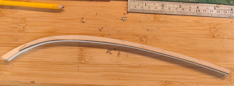
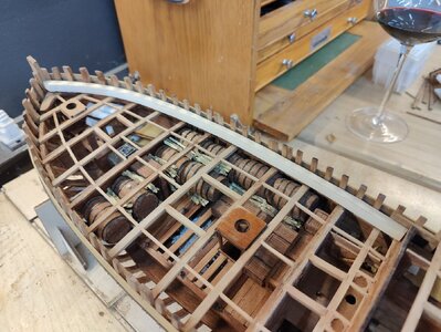
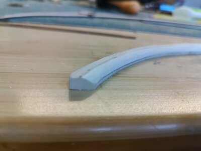


I also wanted to point out that this approach seems to offer the advantage that no reworking of the deck planks is required because the replacement waterway is the exact width of the original. However, it seems to me that 1/4" (6mm) might be a bit too tall? This would be 12" (0.28m) in full scale. Is that accurate?
Very nice and precise work on the runner. I know the problem with the doors all too well.
Hallo,
i sanded this edge - all cutting with a power tool would be too problematic - just handwork
The width of your waterway is not too big - imagine, that on top will be the planking of the sidewalls - so visible will be at the end only the area which is inclined
View attachment 432462
If I'm measuring correctly, the waterways are more or less 8mm. I've been tapering starting at the centerline, so about 4mm in. How wide are the planks which sit above?


