-

Win a Free Custom Engraved Brass Coin!!!
As a way to introduce our brass coins to the community, we will raffle off a free coin during the month of August. Follow link ABOVE for instructions for entering. -

SUBSCRIBE TO SHIPS IN SCALE TODAY!
The beloved Ships in Scale Magazine is back and charting a new course for 2026!
Discover new skills, new techniques, and new inspirations in every issue.
NOTE THAT OUR NEXT ISSUE WILL BE MARCH/APRIL 2026
- Home
- Forums
- Ships of Scale Group Builds and Projects
- Le Coureur 1776 1:48 PoF Group Build
- Le Coureur 1776 1:48 Group Build Logs
You are using an out of date browser. It may not display this or other websites correctly.
You should upgrade or use an alternative browser.
You should upgrade or use an alternative browser.


Looking very good 
Starboard side up next. I decided it would be easier to start from the top down (planks 12-5) and then work my way up. This worked out really well, as it's then becomes possible to center the garboard strake properly.
This method eliminated almost all need to modify the planks. It did prove that there is a very significant gap between planks 4-5. I'll post a photo of this later.

This method eliminated almost all need to modify the planks. It did prove that there is a very significant gap between planks 4-5. I'll post a photo of this later.
This is looking very good - very clever idea with the sticks and clamps (Why I did not get this idea, when I needed it?  )
)
)
That may be the reason why we are all on this great forum.This is looking very good - very clever idea with the sticks and clamps (Why I did not get this idea, when I needed it?
")
Similar problem on the port side... an oddly spaced plank was cut to fit and everything was sanded down.
I then proceeded to the aft inner planking. As others have noted, the precut shapes don't fit very well.
I confirmed this by measuring the frame height with a piece of paper. I marked the original plank heights over this and it was much too short. I then measured equidistant lengths using a fan pattern and transferred to the frame.


With these marks in place, it was much easier to visualize how the planks should be laid out. This enabled me to use just a single stealer on the first plank and then shave the planks above to fit using a rotary drum sander.
This eliminated the need for multiple stealers (great!). I ended up needing an additional plank on top, which I borrowed from the unused planks on the port side.
The fore planks were much easier and only required a bit of sanding down. I still had one plank to go when the photo below was taken.

I then proceeded to the aft inner planking. As others have noted, the precut shapes don't fit very well.
I confirmed this by measuring the frame height with a piece of paper. I marked the original plank heights over this and it was much too short. I then measured equidistant lengths using a fan pattern and transferred to the frame.
With these marks in place, it was much easier to visualize how the planks should be laid out. This enabled me to use just a single stealer on the first plank and then shave the planks above to fit using a rotary drum sander.
This eliminated the need for multiple stealers (great!). I ended up needing an additional plank on top, which I borrowed from the unused planks on the port side.
The fore planks were much easier and only required a bit of sanding down. I still had one plank to go when the photo below was taken.


Here's an aft view of the ballast box. The close up shows some gaps in the barrel tops but they aren't that visible in person (especially when the barrels will be eventually turned on their sides).
Not shown here but I cut about half of the planks which sit on top of the ballast box. They look nice with tung oil but will largely be hidden under a nearly full cargo hold.
As for the ballast itself? I'm thinking gold ore. Not historically accurate but pretty to look at.

Not shown here but I cut about half of the planks which sit on top of the ballast box. They look nice with tung oil but will largely be hidden under a nearly full cargo hold.
As for the ballast itself? I'm thinking gold ore. Not historically accurate but pretty to look at.
Looks absolutely great. I like your work.
Very good progress - it is looking very good
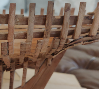
While working through the interior, I realized that I wasn't going to make any serious progress until I finished planking the outside of the model. So without further ado, I freed it from the jig.

Using a small syringe, I injected acetone into the joints of the side panels. This eventually loosened them enough where I could peel them from the jig.

The boat gradually emerged as the panels were removed.


It wasn't possible to easily remove the vertical pieces, so I had to snap these off and soak the bottom joints in acetone, prying them out with the tip of a file.


Next up was to assemble the mounts for part 2. There appears to be a pretty serious mistake here. The slots aren't cut long enough, so the perpendicular stabilizers sit flush with the lower tabs. I had to extend the slots.

Finally, I was able to sit the hull in place... but there was yet another mistake in the kit! Aft sits flush with the mounting board but fore sits about 1/2" above. Part C4 needs to have a slot cut in it and the spacing must be widened.


Eventually... success. The hull sits flat and is much more secure than before.

Using a small syringe, I injected acetone into the joints of the side panels. This eventually loosened them enough where I could peel them from the jig.
The boat gradually emerged as the panels were removed.
It wasn't possible to easily remove the vertical pieces, so I had to snap these off and soak the bottom joints in acetone, prying them out with the tip of a file.
Next up was to assemble the mounts for part 2. There appears to be a pretty serious mistake here. The slots aren't cut long enough, so the perpendicular stabilizers sit flush with the lower tabs. I had to extend the slots.
Finally, I was able to sit the hull in place... but there was yet another mistake in the kit! Aft sits flush with the mounting board but fore sits about 1/2" above. Part C4 needs to have a slot cut in it and the spacing must be widened.
Eventually... success. The hull sits flat and is much more secure than before.

One of the issues I've had with this kit is that the rear left of the jig was not accurately cut. I suspect that this might be linked to the problem various members have reported with frame 35. In the previous photo, you can see that this frame appears to be sitting just a bit too low. I am leaving the port side unplanked so fortunately this will end up being a cosmetic issue... but there's a similar issue on the starboard side that will have to be dealt with.
Interesting - I did the same working steps the last days
Very good explanations of the small problem with the adjustments to the jig.
One info referring the frame 35 - I did not have the problem, that the frame is sitting too low, I think, that it is important to follow strictly the fairing line of the frame floor timber in connection with the keel
Very good explanations of the small problem with the adjustments to the jig.
One info referring the frame 35 - I did not have the problem, that the frame is sitting too low, I think, that it is important to follow strictly the fairing line of the frame floor timber in connection with the keel
Frame 35 fit pretty squarely in the keelson. However, one of the frames a bit further fore (#33 or 34 maybe, I'm not by the ship to check) was not touching. This is super annoying because I checked a bunch of times but still didn't see it.
I took the opportunity to wire brush the frames on the port side to clean off most of the char. Then I took a stab at fixing it.

I filled the gap with a small piece of wood but I'm not really happy with it. The steps still sit a little too high relative to the frames fore and aft. I could dissolve the glue and try to reseat the frame but then it seems like the steps will sit too low.
I'm not really happy with how the stern frame steps (joggles?) came out either. These were the first ones I did and they are a lot sloppier in comparison to the rest. So... not museum quality. But this is an extreme closeup and looks pretty incredible for a piece intended to sit in the home.

Next, I noticed that one of the frames around 20 was not parallel with the rest. Funny how you start to notice more detail as you get a little experience (this is my 2nd ship, the first being the beginner model, Swift 1805).

The only solution for this was to inject acetone into the space between the frame and where it contacted the hull clamp and inner planking. After a few minutes, the upper two pieces broke free from the rest. I cleaned off the dissolved glue and clamped it back in place, parallel with the rest. It's still drying so I don't have a photo yet.

Next up are lots of little dried globs of Weldbond like these. To deal with them, I'm wiping acetone on with a paper towel and then gently scraping off the remnant. I followed this up with a little light sanding.

I took the opportunity to wire brush the frames on the port side to clean off most of the char. Then I took a stab at fixing it.
I filled the gap with a small piece of wood but I'm not really happy with it. The steps still sit a little too high relative to the frames fore and aft. I could dissolve the glue and try to reseat the frame but then it seems like the steps will sit too low.
I'm not really happy with how the stern frame steps (joggles?) came out either. These were the first ones I did and they are a lot sloppier in comparison to the rest. So... not museum quality. But this is an extreme closeup and looks pretty incredible for a piece intended to sit in the home.
Next, I noticed that one of the frames around 20 was not parallel with the rest. Funny how you start to notice more detail as you get a little experience (this is my 2nd ship, the first being the beginner model, Swift 1805).
The only solution for this was to inject acetone into the space between the frame and where it contacted the hull clamp and inner planking. After a few minutes, the upper two pieces broke free from the rest. I cleaned off the dissolved glue and clamped it back in place, parallel with the rest. It's still drying so I don't have a photo yet.
Next up are lots of little dried globs of Weldbond like these. To deal with them, I'm wiping acetone on with a paper towel and then gently scraping off the remnant. I followed this up with a little light sanding.
I'm probably going to be at this cleanup job for a few days. I still need to wire brush off the rest of the char on the port side frames. In hindsight, this would have been much easier prior to assembly.
Frame 34 (or so) is still bothering me, so I might need to dissolve the glue and push it down into the keelson. I'll probably have to build up the inner surface with a spare piece of wood to keep contact with the inner planking.
Some of the steps (joggles?) are less than perfect. But the model looks really, really good from anything farther than a foot away.
Well, well, well. I have a lot of cleaning up to do before I go farther. Part of the problem was with the jig but most is with the modeler!
I decided that I would just slow down, carefully assess my errors and fix each in priority order. At least until I grow impatient again.
Here's a good example, the port side #35 and 36 frames. Frame 35 sits too low, while frame 36 is not parallel and sits too high.

From above, you can also see that frame 35 sits too far out and has to be brought slightly in towards the centerline.

Frames 35 and 36 are removed by injecting acetone into the joints until the Weldbond dissolves. I noticed at this time that some of the steps are pretty sloppy, so I took the opportunity to file them into better alignment.

And here is the corrected version. Using a steel ruler, I confirmed that frames 35 and 36 now align properly with 34 and 37. My corrected steps aren't as deep as the originals, but I think they will look fine once Tung oil is applied.
This was not a fast process. It took about 90 minutes to fix these two frames. I have 5 more major errors to fix after this.

I decided that I would just slow down, carefully assess my errors and fix each in priority order. At least until I grow impatient again.
Here's a good example, the port side #35 and 36 frames. Frame 35 sits too low, while frame 36 is not parallel and sits too high.
From above, you can also see that frame 35 sits too far out and has to be brought slightly in towards the centerline.
Frames 35 and 36 are removed by injecting acetone into the joints until the Weldbond dissolves. I noticed at this time that some of the steps are pretty sloppy, so I took the opportunity to file them into better alignment.
And here is the corrected version. Using a steel ruler, I confirmed that frames 35 and 36 now align properly with 34 and 37. My corrected steps aren't as deep as the originals, but I think they will look fine once Tung oil is applied.
This was not a fast process. It took about 90 minutes to fix these two frames. I have 5 more major errors to fix after this.