Le Coureur 1776 CAF Model by OT1138

I can't stop laughing ROTFI think he was lucky that the ship was stilll in the shipyard. Despite Long Johhn Sillver and the huge number of other pirates having a wooden leg in stories like 'Treasure Island' I don't think many warriors at sea - pirates or not - had a wooden leg IRL. Not that they wouldn't get injured. On the contrary many a brave sailor in the 18th century has likely lost a limb or two - or other extremities - in the battles but I think in nearly all cases this would have lead to death.
 
Last edited:
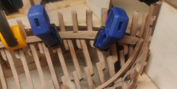
Planked the back counter. I soaked the planks briefly and ended up with some gaps. They seemed a little large to me so I continue to think that the rear left of the jig is off, adding a bit of skew to the ship. I filled in the gaps with dilute wood glue and sanded.

Uwe's look more even on the sides... I wasn't overly concerned with this as the edges will be hidden by the deck clamps. I believe the entire surface will be largely covered up in fact.

1606694186535.png

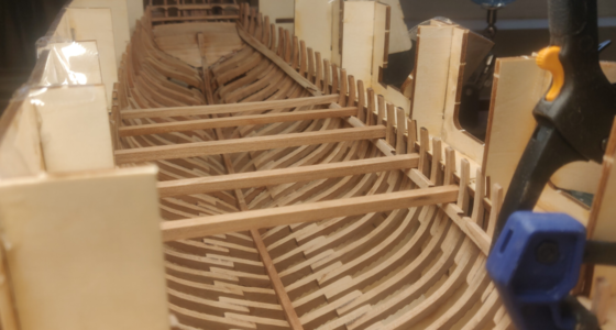
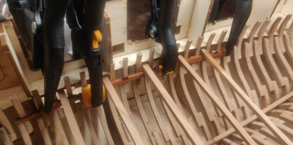
Next up were the lower deck clamps. Positioning of these using the measuring sticks has been covered elsewhere. I bent the clamps by soaking for 12 hours, setting in a curved jig and applying heat using a travel iron. I then soaked them again and clamped them in their final location, allowing them to dry.

Another good tip here is to start with the middle clamp, then do the rear and front, sanding the ends to fit.

1606694440287.png

1606694473556.png

1606694512629.png
 
Very good work - and it is looking very good
Great Thumbsup Thumbsup
 
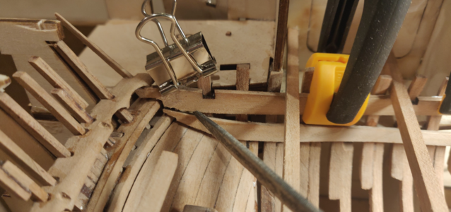
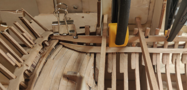
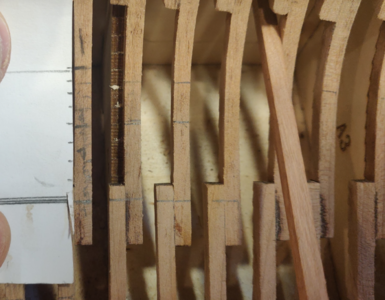
Port side upper clamp deck is next. Careful fitting followed by gluing... then I noticed that there didn't seem to be enough space between the upper and lower clamps (note where the tip of the file is inserted).

1606788834679.png

I consulted the plans and it appears that the lower edge of the upper clamp should be level with the shelf that it rests on. I quickly removed the clamp before the glue dried, sanded the aft lower edge to a gentle taper and reinstalled.

Much better.

1606788954756.png
 
Moving on to the inner planking, it seems there is an error here somewhere.

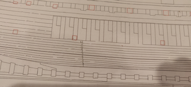
So let's assume you believe this plan, specifically that the #12 inner plank should end butting under the horizontal measuring sticks (red squares). This seems pretty reasonable.

1607183898642.png

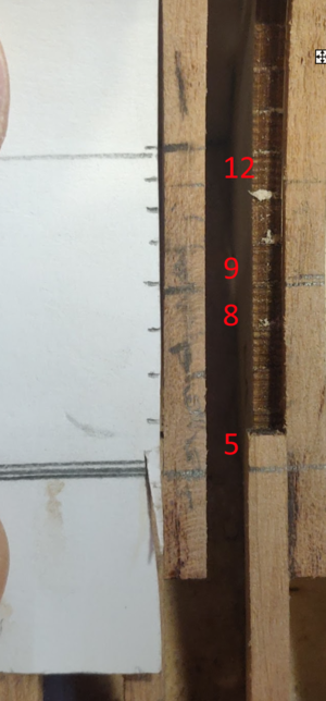
However, I transcribed the plank heights to a piece of scrap paper. As noted in Uwe's log, planks 1-4 fit snugly together and so do 5-12. However, there is a suspicious gap between planks 4 and 5.

I then pressed plank #12 into place, butting it against the horizontal measuring sticks and drew a line where it intersected the frames. Using that line, I positioned the scrap piece of paper and marked off the location of planks 1-11. The marks weren't perfectly aligned due to the width of the planks, so just to be sure I fitted planks 9-12 and traced their lower edge. Then did the same with planks 5-8.

1607184237891.png

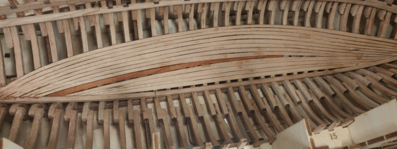
This leaves a rather large gap on the bottom of the frame, enough to fit 6.5 planks (not 4).

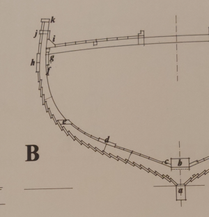
We know there is a limberboard in there but there's still room for another large plank. This is probably the missing plank "d" depicted on the Boudriot plans.

1607184374713.png

The correct way to plank this would probably be planks 1-4 (in order), followed by planks 12-5 (in order). The the missing plank D has to be hand cut and fitted.
 

Attachments

  • 1607184078944.png
    1607184078944.png
    1.8 MB · Views: 10
I also wonder if this explains the need for stealers others required when fitting the stern inner planks.
 
Working from the top down showed that the garboard strake and upper planks (planks 1-4) were installed a bit too far forward. I attempted to follow the plans and installed the fore tip of the garboard strake at frame 6... it would have been much better to install it perhaps at frame 7. This resulted in an uneven gap between planks 4 and 5.

1607294672099.png

I intend to fit a raised plank ("d" in the Boudriot plans) but this gap is too wide, so I created a filler for it. Using blue painters tape, I cut a rough fit and then gradually sanded it down with a drum tool to fit.

1607294781743.png

Test fit:

1607294810850.png

Pretty decent. I left a bit of space on the bottom edge as this will be covered up with the raised plank "d".

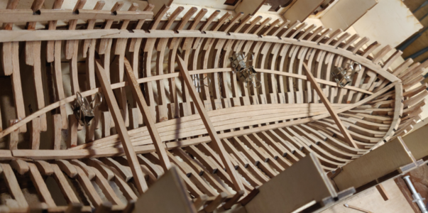
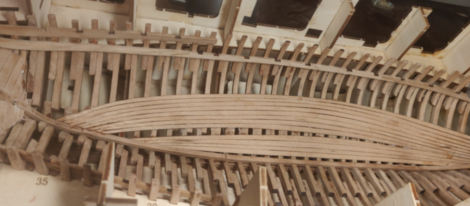
While it's drying, I took the opportunity to assess how much clinkering (and thus sanding) is going to be needed. I do this by shining a light from above and seeing where the shadows drop. Most of the clinkering is at the fore and aft ends... there's relatively little in the middle due to the fact that the planks were properly cut to fit. I also noticed that the tip of my stealer around frame 7 is slightly raised... will need to glue that down.

1607294953110.png

Next step will be to fill the cracks with dilute wood glue and give it a good sanding to fill in the gaps.
 
So while I'll reproduce the same positioning on the starboard side so that the planking pattern matches, I would do things a bit differently if I was starting over.
  • I would fit the planks together and transfer them to paper in three places - middle and near both ends of the garboard strake (being careful to note which frames the marks match with).
  • Next, I would fit plank 12 first using the horizontal measuring sticks.
  • Then I would transfer the marks from the strips of paper to the appropriate frames. The important mark would be the bottom of plank 5.
  • Using these marks, I would then fit the garboard strake so that its top edge is parallel to the bottom edge of plank 5.
  • Then continue with plank 2-4, followed by 11-5 (in that order).
  • This would leave a small gap which could be filled with A) a plank of the same thickness as the rest or B) a slightly thicker plank to match the Boudriot plans. In my case, plans 4 and 5 are not parallel so I will overlay a thinner plank on top.
 
Has anyone given any thought to a planking pattern to use for the inner planking?
 
Another question... what type of wood is the inner planking? There does not appear to be enough scraps to make a plank "d".

As for the shape of this plank itself, it appears it should be shaped similar to #5 though a bit wider (exact measurement can likely be lifted from the Boudriot plans). It is positioned in about the same place, roughly at the upper end of the junction where the #20 frame lower and mid frame sections meet.
 
I doubt the thick stuff was one long plank. If you make it in 2 planks there seem to be lots of extra wood e.g. on plate 1M & 1N. This board is a little thicker than board 1O & 1P so in your case it is maybe not directly useful. Assuming you are only using one of the boards 1S & 1T as well as either 1R or 1Q maybe you can get the extra planks out of the 2 not used board.
Besides, I think there are plenty of extra 1.5x5 mm lists. These or the extra wood from 1M / 1N could be sanded down to proper thickness
 
Last edited:
Thanks for the tip on the wood!

The Boudriot plans state that the mid-plank is made of two parts, though he doesn't provide any further detail. I would assume that it means there are two parallel strips which make up the plank (otherwise why say anything?)

Plates 1M and 1N likely have enough wood if doing 2 strips on each side. The question is how long (exactly half the length of the ship?). Perhaps this is related to the earlier question about a nail and planking pattern.

I think these planks have to be custom cut. Making them from 1.5x5mm strips will probably clinker.
 
Last edited:
Looks like 1M and 1N are the same thickness as the inner planks (~1.37mm). So that could work!
 
Back
Top