Le Coureur 1776 - French Lugger 1:48 - CAF by Alex

Joined
Oct 30, 2019
Messages
206
Points
253

Location
Houston, Texas, Park City, Utah
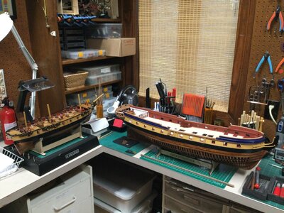
Today I finished (well, almost) my Caldercraft HMS Snake 1:64 that was on the building dock for years...This allowed my ongoing build of HMS Enterprise to move to a different location in my shop. It still needs a lot of work, but all structural work is done. The shop is now re-configured to start Le Coureur. Keel first, then frames, then build-jig. 03E766D5-EB41-4A08-A129-265EC77BF0DD.jpegCE02FA5A-6064-44F1-8160-053959978121.jpeg
 
Hallo Alex,
good news, that you will start in short time the work on the Le Coureur from CAF.....
As we know the modeling quality of the other models, we are very happy to see your lugger in this building log.....

And congratulations for finishing the HMS Snake, so we can expect some more photos of her in your log....
 
KEEL
The keel structure is glued and drying under a glass pane. It fits the lines in the plan exactly. However, you will notice that there are several gaps, most notably between the stern post and rising deadwood. The gaps are superficial, only on one side- the joint below is square and tight. The laser did not cut all the way through several keel pieces contained in sheet # 09-box 1, so I had to "sculpt" the pieces out resulting in the edges not being perfectly square. The keel pieces out of sheets #8 and # 10 were all well cut by the laser. I will fill the superficial gaps with wood putty after the keel is completely dry and has spent at least 24 hrs under weighted glass.

9BFC91CC-222C-4C1B-BA4C-4F363C741C69.jpeg

FRAMES
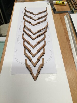
Started frame construction. Initially, I cut out the plan drawing for each frame and glued it to flat pasteboard with UHU glue. Then I glued parts "A" and "C" to the plan with UHU glue, checking for alignment by looking from different angles. I placed some pins to keep parts for moving, but this is not really necessary...
After looking at UWE's build and the discussion of when to clean up laser char, when to bevel etc., I tried a slightly different several method on each of the three frames I made today.
Frame # 5: Lightly sanded the laser char from the back of the sheet, and cleaned parting ridges. I did not sand any notches or make bevels. This will need to be done later
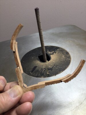
Frame # 4: Light laser char sanding of the inboard aspect of the frame futtocks, no beveling, using spindle sander, before assembly
Frame # 6: Light laser char sanding of inboard aspect of futtocks, no beveling. Hand sanding of the notches on the exterior aspect off the futtocks, before assembly.

I think that for the rest of the frames I will:
1) Lightly sand the inboard side of the futtocks and centerpiece, making the laser cut 90 degrees. This gets rid of the error introduced when futtock "A" or the center piece are glued to the plan. As we all know, the laser cut is not perfectly perpendicular to the table but has a very tiny angle, making the bottom of the piece a tiny bit broader than the top. By sanding the laser char and angle off, this error is eliminated.
2) Hand sand each exterior notch in each frame, for the same reason as above. Also, I think it is a lot easier to sand the notches flat and clear of laser before assembly than once the frame is assembled.
I got some very small Corradi files, pictured below, that are ideal for this....Thanks to UWE for his recommendation of these superb files!
3) Beveling should be done on a fully assembled frame. The bevel angles and size of the pieces are such that the bevels would not match up well (IMO).
4) I placed a scrap piece of wood, of the same thickness as the frame, underneath futtock "B" to keep the frames straight while the heavy plate glass is on them.
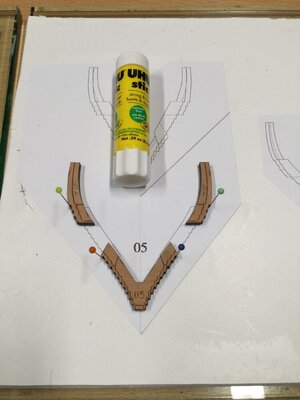
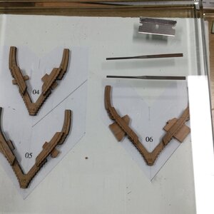


CFC511B4-B520-4820-86D3-3F9518E19D93.jpegAB778466-D478-4F1B-8335-7CCCE8A24E79.jpeg
 
Last edited:
Build update:

Making frames; a slow but very enjoyable process. Have to be careful not to inhale laser char dust ! I use a respirator and suction nearby.

I have been lightly sanding the notches on most of the frames, just enough to make them sharp. It may be a waste of time and effort since I will eventually have to sand all the bevels and that will take care of the char. I just find it more accurate (satisfying) to do it this way when placing the futtocks on the drawing.

I should have listened to my fellow builders and started with the midship frames first, as they are easier, but instead I started on frame 4 and I'm working my way up towards the stern.

Once I have all the frames made, I will sand the bevel on all of them. Both inside bevel and the notches.

Question: Should I construct the building berth and sand the bevels on each frame as I place them in the jig (using both the bevel lines and the fit on the building berth, or sand them before using the bevel lines as a guide ???

Question: Is there a hand-held motorized file or similar device/method to help with sanding/beveling the small notches ? My beaten-up arthritic hands would welcome it !


Light sanding of the notches:
61225C21-47B9-4D41-B471-D936ED32D8F8.jpeg
frames 4-12 built,
653099F9-C79F-4152-8701-766374C3D57E.jpeg
 
I tried to use a vibrating sander from micromark for this but it did not work. It took sharp files for me.
 
Thanks for the advice. Just as I finished asking the question in my previous post it occurred to me to see if the hand file would fit into the Micromark motorized detail sander. It has a reciprocating movement only. Great minds think alike ??
I put in a couple of files (looks like most files will fit-depends on diameter of handle) and it works on a test piece. ! I will try it out later and see if it works. I hope so.


Here is he verdict: It doesn't work for me. One looses the feel that you get with the hand file. The sander shakes too much in the hand. No help at all. I'll be hand filing for a while !
123048FF-7EBF-4168-827B-6C936EE9DC72.jpeg
 
Last edited:
Very good work
and I agree fully with your described working steps - it was at the end also my experience to do it in this way.
 
Building update.
1) As of last week, all the frames were assembled.
2) The building berth was assembled after most of the frames were assembled. A description of building the berth is to follow.
I skip around a bit, but essentially I am following this sequence:
3) beveling the smooth edges of the frames inside and out
4) Once the smooth sides are beveled, bevel the notches. Test fit each frame into the notches in the berth to check beveling.
The picture below shows beveling of smooth edges with rotating sander.
FA781992-B882-4A79-A53B-BE9BEF7169FD.jpeg
Below: The notches have to be beveled-sanded by hand.

B120E4DD-172E-4FDE-8DDA-D92A708423CF.jpeg


Building Berth: A few tips that were EXTREMELY HELPFUL
1) I did not glue the A 1-7 vertical parts to the base. Instead, I glued 4x4 mm wood guides along the notches tightly against each "A" piece to keep pieces A1-7 removable, and always positioned at 90 degrees.
2) All of the notches on A pieces 1-7 were sanded off. These serve no purpose, and interfere with dry-fitting of the frames that fit over them. Since the notches on the frames contact the A pieces in different places depending on the frame, I sanded off all the notches in each "A" piece.
3) Rubber bands on top of the A pieces are placed across to keep the A pieces tight.
4) Any A piece can be removed and replaced easily.


4E084BEA-9BCA-4137-BD43-5EC28E448D9D.jpeg

D1B03EC3-33B5-40EA-906F-6F5BB81AF4D6.jpeg

This shows the notches on A pieces 1-7 after sanding, and the corresponding frames dry-fitted.
9906B4A8-63C6-483A-B4AE-FCB5F9F7FFB6.jpeg
The building berth with removable A pieces, with frames (in various stages of beveling) test fitted.

D94DA64F-C79E-4F2B-829E-B5F54416F900.jpeg
 
Last edited by a moderator:
Very good progress! Thumbsup
and many thanks for summary the most important points, which will help other modelers

I have a principle question about the use of your rubber band which are installed at every "A"-axis. Especially because you did not fix the "A"-elements on the base.

D94DA64F-C79E-4F2B-829E-B5F54416F900.jpeg

The rubber bands are producing a force to the center (red arrows) and caused by the rotation center at the base (green crosses) you will have an uplift force at the outside (blue arrows)
Maybe it can happen, that especially at the midship area the jig has an intention to get smaller (red arrows) and produce pressure against the frames. And this pressuer would be against all frames due to the small deformation of the horizontal part C1 and C2 - the worst case would be, that your hull is getting slightly thinner than others, means the width of the ship.

My hint is only for brain-storming - maybe you check once more the influence of your rubber bands ......
 
Hi Uwe,
Thanks for your engineering analysis. I thought about this problem when I did this initially, but didn't really check the effect once all the frames were in. You are right ! there is a very slight lift on the outside of some of the A elements which produces an rotation causing an inwards pull exerted on the top of the frames.
How to deal with this ?
1) Place a "stop" at the innermost end - rotation center) of each "A" piece (drilling a hole and inserting a pin, or glueing a piece of wood) to keep it from rotating downwards...seems too complicated....
2) The purpose of leaving the A pieces unglued allows me to insert and remove frames easily, leaving room to work on them without breaking. I would like to keep them removable rather than glue them in.
4) As each frame is being worked to be permanently fixed to the keel, I will remove rubber bands, and nearby frames; there won't be a rubber band nearby causing rotational pressure.
5) Once all the frames are correctly glued and fixed to the keel, and the transom is in place, I can install the "D" side panels if needed to fix and keep the A Pieces from rotating. I imagine that this will provide stability for installing the deck beams and inboard planking.
What do you think ?
Meanwhile, all the frames are now beveled, and I am now working on the tedious job of sanding and beveling all the serrations on the outside of each frame by hand. This should take me at least a week ( I don't like to do more than 2-4 frames each day...make mistakes, etc, etc). I have also cleaned up and dry-fitted all the transom structures..this will be a comp[licated project in itself. I will follow your process on the transom for sure.
Alex
 
I don't think you need the rubberbands at all. What I did to keep the A pieces in place on the berth: Some of the extra squarre wood pieces I glued to the side of the A walls instead of gluing them to the bottom plate. In these sqarre pieces I had drilled holes so I afterwards could fix them to the buttom plate with small screws. However, I found the whole berth very rigid, all the A wall tabs fit really tight and it would take a lot of force to lift any of he A walls so in the end I did not use any screws
 
Hi Poul
Although I did not sand any of the tabs, some of the A pieces did not fit very tightly in my building berth. I agree that I don't need the rubber bands in all the A pieces, only in a couple of them, and only temporarily. ....Good discussion. By the way, I noticed you are from Roskilde. We (wife and daughter) went to Roskilde November 2019. We enjoyed the Viking museum and the ships there. I especially liked the real viking shipyard where they build the viking ships in the traditional waytempImageVoxHX3.jpgtempImagegAEHd0.jpgBF504A57-1517-4F54-B197-F87547308F4E_1_201_a.jpegtempImageLoBPIh.jpg
The Roskilde Cathedral is also wonderful. I love your city !
 
Last edited:
Build update:

The stern is assembled-and I didn't break anything ! The stern is always a very difficult part to construct due to many parts, odd shapes, little support when initially building, etc., etc.,etc.. I still need to do a little clean-up/sanding, but the assembly fits the
berth well.

With a few modifications, I generally followed the build process so well detailed in Uwe's build.
1) The frames and keel structure were removed from the berth.
2) The curved central stern timbers (11 1-4) were glued together outside the berth and the center slot sanded to fit into the curved rabbet cut into the sternpost
3) The keel was then replaced on the berth and the central stern timbers were glued into the sternpost rabbet with piece 11-1 resting directly on piece A-9 of the berth to determine the correct angle.
The berth structure was also used as a guide to glue the fashion pieces to the rabbets on sides of the sternpost and the central pieces of the stern
5) The Fashion pieces were glued to the sternpost and stern timbers, again using the building berth to position them correctly. After the glueing of the fashion pieces was dry, the transom pieces 11-12 and 13-1 were inserted and glued the keel structure/stern was removed from the berth.
6) The rest of the stern pieces were installed outside the berth, and the completed stern structure cleaned up and sanded.
7) The keel and stern structures were replaced into the berth.

Picture below shows the completed stern on the keel fitting well into the slots of the berth.....some clean-up left to do.
B8BF5C97-C8B5-4D84-AA77-9D0BA8EF93B6.jpeg
 
I'm sorry to say Alex but to me your stern does not look right. The 2 pieces I've marked with red arrows seems to be in a wrong position and they are also covering the 2 mortises for the deck carlings:
1612997587648.png
I believe they should be placed like this:
1612998113634.png
It also seems as if you have switched the lower and the middle transom:
1612998225364.png
 
Last edited:
Yes, Poul
U are right. I realized it after I posted it-it didn't look right...aAs you point out, I made a stupid mistake installing the transom piece 13 above above transom piece 11-12. That was the root mistake. That's why I everything above was wrong. I am going to re-do it, but I may need new stern parts.....This just confirms that I am no good at sterns!. If I break it, I will have to ask Tom for new parts.....
Alex R
 
Many Thanks to Poul for looking in detail - and he is right.

The stern structure is really a very delicate element of the hull structure, so it needs to be done step by step.

Here is the link to the posts describing the stern:


Depending on which type of glue you used (maybe you can open the joints) you can maybe adjust your stern structure

It should look (somehow) like this one:

IMG-4745.jpg IMG-4746.jpg IMG-4748.jpg

 
I'll have to wait for Tom to send me parts to re-do the stern....May be a while because of Chinese New Year on Friday
Meanwhile, I'll work on sanding frame serrations....and I am still working on HMS Enterprise...
Being careless/stupid has consequences !
Alex R
Hi Alex,

Try to dissolve the glue (if it is PVA) with nail polish remover. It works quite easilly if you use cotton swaps. Then you can dismantle the stern without any breakage and reuse the parts.
 
Hello Maarten
I tried dissolving the glue, but the fashion pieces snapped where the middle transom joined. (actually, I snapped them, they didn't break themselves !)
I could have spent a lot of time, and maybe re-made the stern with the original pieces, but I didn't think it would look good and I was frustrated; Best to start fresh. Tom has already sent me the pieces that I need. I will be going out of town for 2 weeks, but hopefully the parts will arrive by the time I get back and I can tackle the stern again.
Alex R
 
Build Progress.
After almost three weeks away from the build, I received the stern pieces from Tom and re-built the stern, this time correctly. It fits well in the building berth. While waiting for the stern pieces, I finished building up all the frames, and sanded down the inboard bevels. I have faired the outboard clinker serrations in 15 frames. tempImageRVbkqQ.pngtempImagegjAZZN.jpg
 
Last edited:
Back
Top