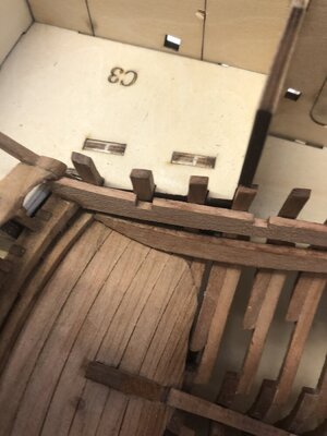
Le Coureur 1776, model 1:48 by Adi

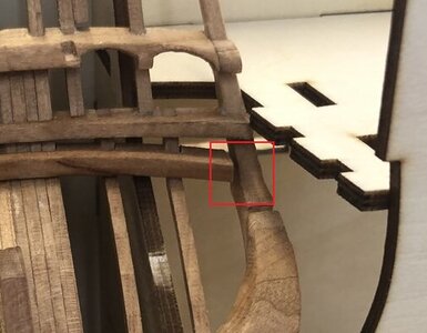
Your stern section looks very good, but is it on purpose that the lower transom is not connected to the side counter timbers?
1610728208970.jpeg
And one more thought: I'm not sure if it is a good ar bad idea but I think I would have cut a little of the keel at a later stage instead of adding extra wood to the stern post. The angle of the stern post would be slightly wrong either way and nobody would be able to see if the ship was 1 mm shorter
 
Your stern section looks very good, but is it on purpose that the lower transom is not connected to the side counter timbers?

View attachment 205818
And one more thought: I'm not sure if it is a good ar bad idea but I think I would have cut a little of the keel at a later stage instead of adding extra wood to the stern post. The angle of the stern post would be slightly wrong either way and nobody would be able to see if the ship was 1 mm shorter
Hi Poul, yes you are right, the lower transom is currently not connected to the outer parts, I am not sure if this is allowed, but everything else fits. Whether I still have to do something there will arise.
I had your thoughts on the stern post as well, then I put the complete keel on CAF drawing again and found that the angle is so correct. I then decided to double up, although it might have been possible to do it differently.
 
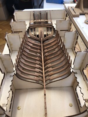
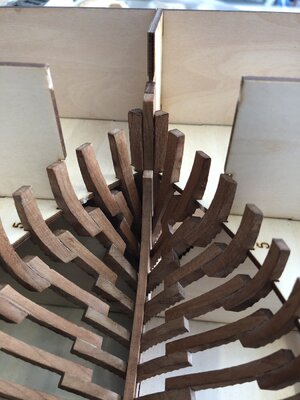
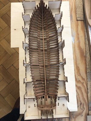
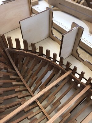
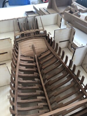
With the frame part 40, I finished the frame installation today. I was amazed at the accuracy of fit of the parts, but still there were a few problem areas.
I first started dry fitting from the center to the stern to check for a clean fit of the frames in the keel. I used the keelson parts as an installation aid to see if everything fit. At the points where the sarration of the frame meet those of the cradle, parts 9, 14, 19, 26 and 32, I partially filed down the sarration of the cradle.
Later I noticed that the sarration in the cradle is not necessary at all, because the clean position of the frames in the keel and the guides of C1 and C2 are completely sufficient.
Coureur_20210127_1.jpg

The parts 34 and 35 did not fit, they were too short, I had probably removed too much by wildly filing around. :oops: There I had to insert a piece again and rework.

Coureur_20210127_2.jpg

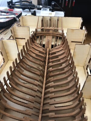
Further installation towards the bow worked out quite well. Only the correct position of frames 1,2 an 3 was a little tricky, with the result that part 1 was mounted a little too high. Let's see how that turns out.

Coureur_20210203_1.jpg

Coureur_20210203_2.jpg

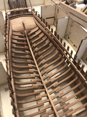
At this stage I then glued the frames to the keel using the keelson as a gauge.
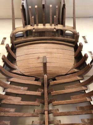
Finally, I installed parts 38, 39 and 40. This could not be done without a little rework. I am quite happy with the result and now I am working on the interior.

Coureur_20210205_1.jpg

Coureur_20210205_2.jpg
 
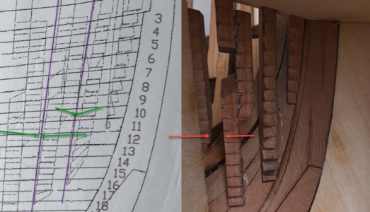
Agree with Uwe, It is looking very good. I noticed one small thing though. I don't know if it is important or doesn't matter. I'm mentioning it while you still have a chance to adjust it if needed. On the plan the half frames in the bow are not vertical but tilted. As you can see frame 3 almost touch frame 4 etc.:
1612535962677.png
 
If it is waterbased wood glue (Ponal f.e.) you can easily with some water remove and correct rge location (I had to make it also - see my log)
Otherwise when it is not possible, and when you plan to cover the hull with planks in the bow area, than you can adjust the teeth according your needs.
 
Hi Uwe, thanks the tip, I guess I will have to go with the second solution as I use waterproof ponal. :rolleyes:
I am using every time the water based one - some drops of water with a brash on the area - and after some waitiing and repeating and some help with a sharp knife into the joint .......
In my opinion and experience for static models the best ......

ES passiert immer wieder einmal, dass man eine Klebestelle wieder öffnen muß
 
Hi Uwe, thanks the tip, I guess I will have to go with the second solution as I use waterproof ponal. :rolleyes:

Very neat work, looks beautifull.

If ponal is PVA you can use nail polish remover, even when it is water resistant.
I use water resistant gorrilla PVA and can dissolve it with nail polish remover.
 
Where would model shipbuilding be without the admirals. So far I have been using her nail files, hair straighteners, washing pegs, nail polish remover and I’m figuring out a way to repurpose a pair of nylons. Any advice is welcome :-)
 
Where would model shipbuilding be without the admirals. So far I have been using her nail files, hair straighteners, washing pegs, nail polish remover and I’m figuring out a way to repurpose a pair of nylons. Any advice is welcome :)
At first I saw a picture I do not want to burn-in on my retina :eek: But if it is fishnet stocking they could perhaps be used for bowsprit netting on a large scale model :D
Speaking of which, I'm using the admirals toothbrush to clean the protein skimmer in my reef tank when it stinks too much
 
Thanks to te good preparatory work of all Coureur blog friends, especially Uwe, the next steps were a little easier for me.
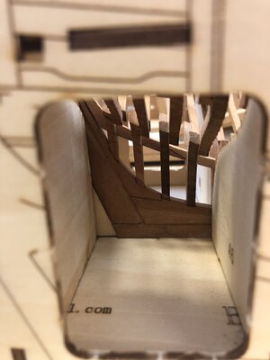
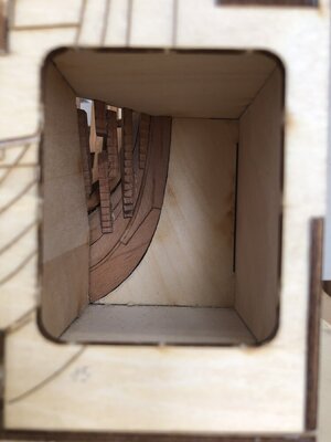
I decided to do the stern ceiling planks first.

Coureur_20210210_1.jpg

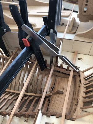
Than I noticed that the deck clamp part 3A-2 has aforced guide due to the 4mm square rods. So I had to start with this part, since the other two, 3A-1 and 3A-3 depend on it.
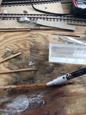
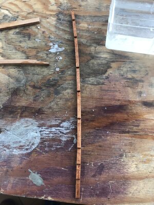
Now the parts had tobe shaped. Since they are not really thin, this job was quite lengthy.
A lot of water and the steam generating soldering iron helped the bending process.

Coureur_20210211_1.jpg
Coureur_20210211_2.jpg

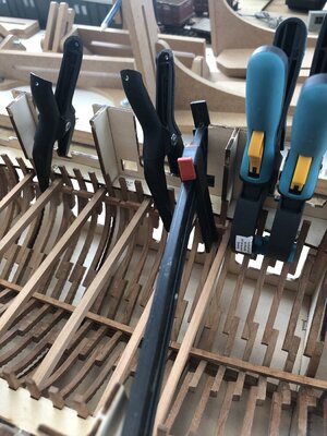
Now put part 3A-2 in position, press it against the square rods from below and fasten it with many clamps.

Coureur_20210218_1.jpg

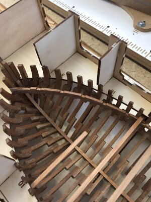
Now fit parts 3A-1 and 3A-3 into to bow and stern. Water, bend, fit.
Part 3A-3 requires special attention because it must be fitted to the curvature of the stern planking.

Coureur_20210218_2.jpg
Coureur_20210218_3.jpg

Coureur_20210218_4.jpg

To install part 2A-4, the sqare rods had to be repositioned. No major problem thanks to Uwe's instructions.
But then I noticed that his green drawn rod, which is responsible for the exact position, had to smaller than 4mm. I used a 3mm piece from the grabble box.
That worked.
Part 2A-4 then had to be reworked in the rear to fit the window opening.

Coureur_20210218_6.jpg
Coureur_20210219_1.jpg

Coureur_20210219_3.jpg
 
Back
Top