Understood yes. Maybe make a custom block yourself for it. Fix it right because the factory may not.
-

Win a Free Custom Engraved Brass Coin!!!
As a way to introduce our brass coins to the community, we will raffle off a free coin during the month of August. Follow link ABOVE for instructions for entering.
-

PRE-ORDER SHIPS IN SCALE TODAY!
The beloved Ships in Scale Magazine is back and charting a new course for 2026!
Discover new skills, new techniques, and new inspirations in every issue.
NOTE THAT OUR FIRST ISSUE WILL BE JAN/FEB 2026
You are using an out of date browser. It may not display this or other websites correctly.
You should upgrade or use an alternative browser.
You should upgrade or use an alternative browser.
Le Rochefort 1/36 by Splinter
- Thread starter Splinter
- Start date
- Watchers 24
-
- Tags
- 1:36 ancre group build le rochefort
Can you determine where in the assmbly, the play comes from? Maybe in the threads that the black knob tightens? Or maybe the surface along the track that the screw tightens to? In other words, where exactly is the 'movement' allowed?Tobias I can't cut wood at the moment because Proxxon Fet is back to the importer to solve the problems with the rip-fence, the problem that the fence moves 1-2 mm left or right after tightening the black handle was known to them and will solve it. I'll let you know when the issues are resolved.
Hi Phil , When the yellow adjusting screw has been tightened to size, then tighten the black handle to tighten the fence, the movement takes place when the black handle is tightened.Can you determine where in the assmbly, the play comes from? Maybe in the threads that the black knob tightens? Or maybe the surface along the track that the screw tightens to? In other words, where exactly is the 'movement' allowed?
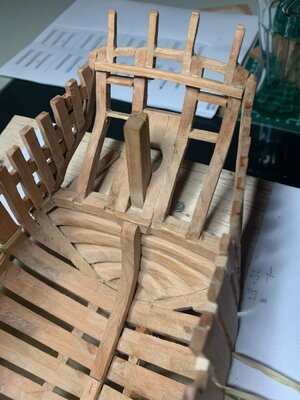
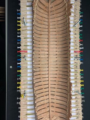
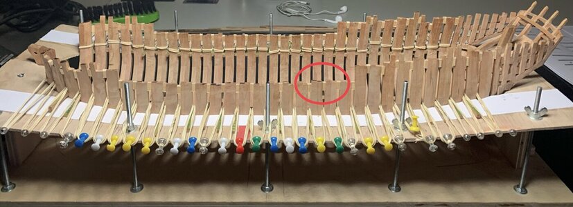
Hi Splitter you can glue your upper spacers, but if possible only in the area that will be cut later. It brings extra stability.Yet another step further, the hull is closed and the floor-timber shocks are placed. Spacers also placed on top of the ribs, the question is whether I should / will glue them. Now just study on the bow first. Fortunately, Tobias showed a few things in his report.
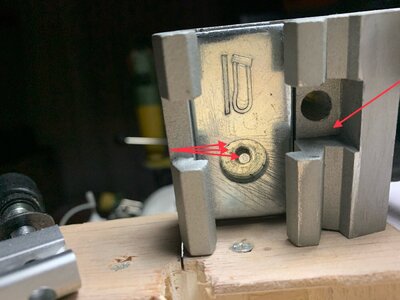
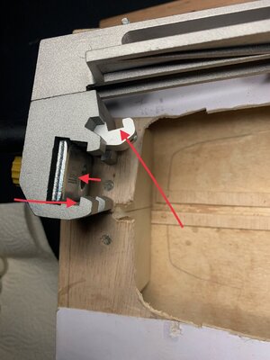
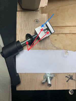
View attachment 358662View attachment 358663View attachment 358664
Your tail turned out really well. If you later come to grind you have to be careful that nothing breaks.
In my ignorance I thought this was normal, and made allowance for this, although the movement isn't consistent. I always test cut with a piece of scrap and adjust both wheel and lever. Time consuming and if unnecessary, I would be delighted if I can have a simple solution/upgrade without sending it overseas for repair.
Can you determine where in the assmbly, the play comes from? Maybe in the threads that the black knob tightens? Or maybe the surface along the track that the screw tightens to? In other words, where exactly is the 'movement' allowed?
The solution to the problem upon inquiry shows that burrs may have occurred during the production process. These need to be deburred. That's why I checked everything for burrs and irregularities. If you remove all burrs from the inside of the guide (the holder where the adjusting screws are located) and also check the screw thread of the adjusting knobs as there are no burrs.
If you then tighten both knobs not too tight, it will stay put.
The irregularities and burrs on the inside of the guide in particular cause it to shift.
Thanks for finding this out Splinter. I will take a close look at my FET saw and de burr as necessary.The solution to the problem upon inquiry shows that burrs may have occurred during the production process. These need to be deburred. That's why I checked everything for burrs and irregularities. If you remove all burrs from the inside of the guide (the holder where the adjusting screws are located) and also check the screw thread of the adjusting knobs as there are no burrs.
If you then tighten both knobs not too tight, it will stay put.
The irregularities and burrs on the inside of the guide in particular cause it to shift.
could you post a picture/s so I can understand EXACTLY the parts to treat.The irregularities and burrs on the inside of the guide in particular cause it to shift.
Splinter very helpful thanks for sharing
I'm always happy when I can help people, I'm glad it worked out for youSurprising amount of burrs. Removed them with significant improvement. Further movement reduction by releasing the black handle only the minimum to allow the adjustment wheel to turn freely. Again thanks for the advice.
Hello everyone . After a week of fighting with the bow, this one is now done. Not entirely satisfied but I'm fine with it, I can use the fireplace to burn all attempts. I have a lot of respect for the people who do and have done this with a milling machine. I couldn't get it done, so just filed and sanded everything. The finishing has yet to be done,
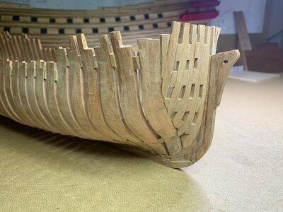
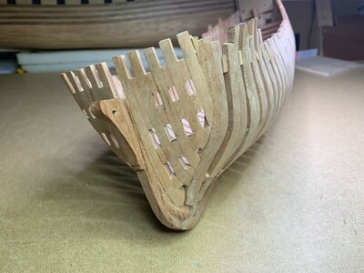


Good morning Splinter, your bow turned out very well. respect for the handwork. As far as your firewood for the stove is concerned, I know that too well, but from La Palme -> it only worked after the fourth time.
Great result and one step further.
Great result and one step further.
Hello everyone, thanks everyone for the likes and the nice comments.
Just a small update on the state of affairs up to today. Now that the hull is closed and that I can now speak of a ship, I have started the next step.
Planking under the deck, a new challenge.
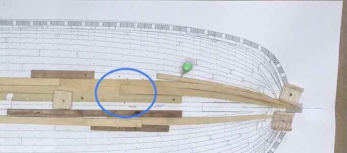
I chose Castello for this planking to get some color difference in the wood. This job will also take some time. Since the working space is very limited, I chose to work from drawing (copy). I work as follows. I take over the measurements from the drawing and that means that cutting and sanding has to be done to get the right shape, if this is good I bend the plank into the shape it should be. I then wet the wood and let it dry, I do this in 2 steps, first step I wet the wood and dry it with a small hair dryer, this almost removes the tension that arises. When this is done I wet the wood again and let it dry in the normal way. the shape is then in place and you do not have to exert much pressure to get the plank in the right place. Then I glue the plank with a super small drop of glue on the drawing so that I can put the next plank against it again. On the bow side I keep a bit of overlap to compensate for any size difference.
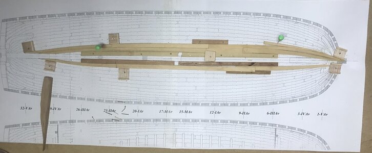

Great idea Splinter, but you have to note that the length of the planks (drawing-> model) can vary slightly due to the bend. What I want to say is that your plan is only the top view, that is, a smooth surface with no depth! According to the plan, the width of the planks also decreases towards the edge, so you would have to switch to the next plan with the longitudinal section. What is also helpful is the plan with the different cross-sections from front to back, here you can also see the width of the individual planks very well and sand or plan accordingly. You are welcome to have a look at my construction report of La Palme starting on page 15.
Hello Tobias thanks you for your help and tip, always welcome. I know that the length of the planks can vary due to the bending, so I take a little more length to accommodate this.Great idea Splinter, but you have to note that the length of the planks (drawing-> model) can vary slightly due to the bend. What I want to say is that your plan is only the top view, that is, a smooth surface with no depth! According to the plan, the width of the planks also decreases towards the edge, so you would have to switch to the next plan with the longitudinal section. What is also helpful is the plan with the different cross-sections from front to back, here you can also see the width of the individual planks very well and sand or plan accordingly. You are welcome to have a look at my construction report of La Palme starting on page 15.
