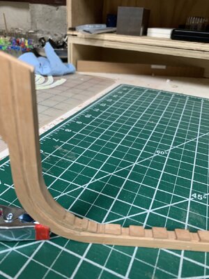
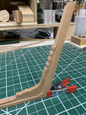
Le Rochefort build log by OlivierF

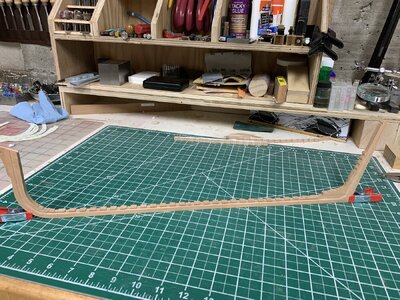
After a few weeks of thinking and looking at the work completed, I’ve come to the hard decision of starting over on this project. I spent most of my adult work life as an engineer and project manager and the most important axiom (or rule) was always, “If the foundation isn’t level, square and plumb your structure will always be crooked.” I learned a boatload in getting this far but my skeleton is simply not level, square and plumb. I keep fighting to get things true, straight and square without success. So (deep breath) let’s start fresh.
One of the most important things I’ve learned is that there is no room to be off by even a millimeter as the deviation compounds very quickly at this small scale.
Therefore, a new beginning…
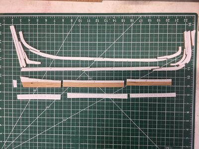
IMG_1187.jpeg
 
Last edited:
Good morning Oliver, my greatest respect, I don't know if I could do that. But as you said some time ago, you are toying with the idea of starting again from the beginning and if you are not satisfied with the result you have to do it whether you like it or not. I am pleased that you are not giving up and that you have the ambition to start again from the beginning and that is why I take my hat off to you.
 
Good morning Oliver, my greatest respect, I don't know if I could do that. But as you said some time ago, you are toying with the idea of starting again from the beginning and if you are not satisfied with the result you have to do it whether you like it or not. I am pleased that you are not giving up and that you have the ambition to start again from the beginning and that is why I take my hat off to you.
Thank you for your words of encouragement Tobias.

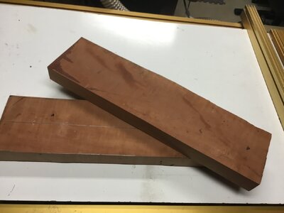
As you saw in my earlier photo, this time I’m starting with the keel assembly. I’m actually going to build two assemblies. One in cherry to try new processes and techniques and the “real” one in Swiss pear. (Thank you @Dave Stevens (Lumberyard)).

image.jpg

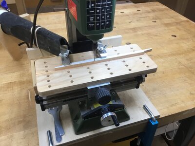
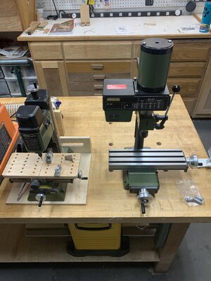
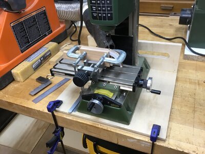
Speaking of new processes and techniques, Merci profondément pour votre idée @Titoneri. I hope you don’t mind that I copied your sacrificial table for the small mill. It works quite well. I may have to get (or make) more hold downs though…

IMG_1194.jpeg

Ok, now that the pear has arrived I need to mill some lumber into usable sizes.
Have a great weekend everyone.
 
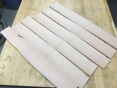
The pear wood is milled and ready.

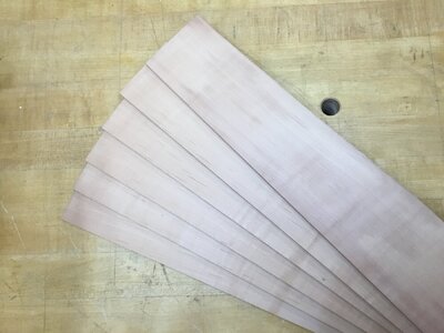
I made the thicknesses 7.6mm for the keelson and other parts, 6.8mm for the rest of the keel parts and 5.4mm for the frames. I’ll sand all the parts to final dimension after cutting out and shaping the parts to size.

IMG_1197.jpegIMG_1198.jpeg

I just need to wait for the printer to tell me the copies are ready to pick up.
 
Once again, thank you Tobias for your mentorship and support. I know I’m not alone in working through new issues and techniques of scratch building with the group’s help. I hope the rest of the group will be back in their shipyards soon as well.
Fair winds and following seas!
 
After a few weeks of thinking and looking at the work completed, I’ve come to the hard decision of starting over on this project. I spent most of my adult work life as an engineer and project manager and the most important axiom (or rule) was always, “If the foundation isn’t level, square and plumb your structure will always be crooked.” I learned a boatload in getting this far but my skeleton is simply not level, square and plumb. I keep fighting to get things true, straight and square without success. So (deep breath) let’s start fresh.
One of the most important things I’ve learned is that there is no room to be off by even a millimeter as the deviation compounds very quickly at this small scale.
Therefore, a new beginning…


a long time ago one of my early teachers in the hobby stresses what he called the creeping thousandth that never goes away it just pops up someplace else in the structure.
One big fail was the steam engine for the Mississippi i drew all the pieces and parts separately and when it came time to assemble the engine nothing fit right. It was just that tiny thousandth here or there and in the end it got me. It is more common than you would think to do a trail run by making a piece out of scrap material before jumping into the actual piece. I remember back in the older generation 1990s in model building post their projects and someone posting a comment of how accurate the built was. what they did not tell you it might be the second or third attempt.
So your on the right track.
My grandson is a civil engineer that will focus on the smallest detail. Growing up my daughter would tell him Jake! let it go and he would always say nope! i can't do that.
 
Thanks Dave.
“Creeping thousandth” is real even in construction. We always maintained that when you do your layout, you start your measuring at point A and measure to point B, C, D, etc. Do not measure from A to B and then from B to C then C to D. If you measure using the latter method the creep factor becomes exponential and what a mess that creates!
 
I have been playing with the mills and trying different ways to get accurate results.
IMG_8426.jpeg
especially with the rising wood. I think I’m getting there…
IMG_8427.jpeg
I still have to complete the stem and stern pieces
IMG_8428.jpeg
I want to give a special “shout out” to Dieter (@Nersch) for posting pictures of some of his setups for using in the mill.
So, thank you Dieter for the inspiration.
IMG_1255.jpeg

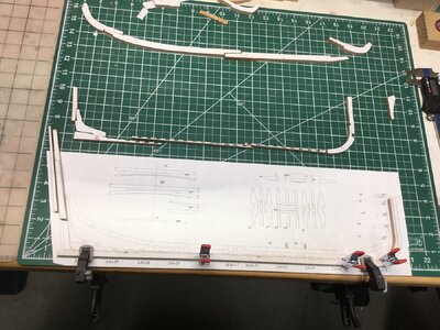
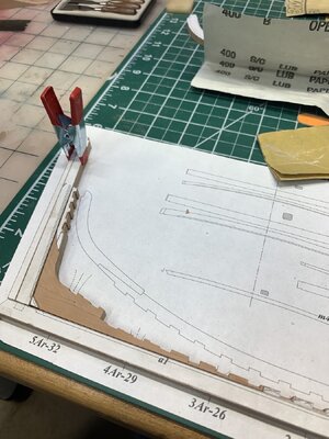
The main keel pieces have been milled and sanded to their final size and they overlay perfectly on the drawings. They are just dry fitted at this point.
IMG_1257.jpeg

I got some reddish/brown tissue paper and will be using that as “caulking” when I complete the glue up.
But for now that will have to wait till next week as tomorrow we leave for vacation.
 
Thanks Dave.
“Creeping thousandth” is real even in construction. We always maintained that when you do your layout, you start your measuring at point A and measure to point B, C, D, etc. Do not measure from A to B and then from B to C then C to D. If you measure using the latter method the creep factor becomes exponential and what a mess that creates!
..and then there is also the 'stone in your shoe' effect..every time you look at the (mistakes in) final model, it hurts more.
It takes courage and determination to start over..respect!
 
I’m slowly making progress on the keel assembly. As noted above the pieces line up perfectly with the plans. This last attempt is a Major improvement over my first three attempts.
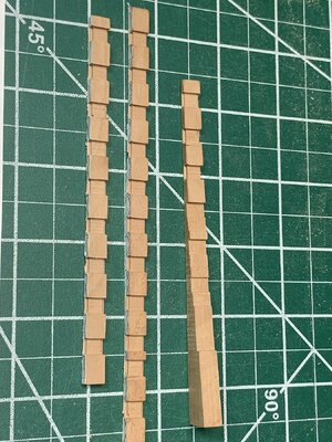
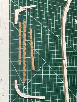
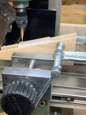
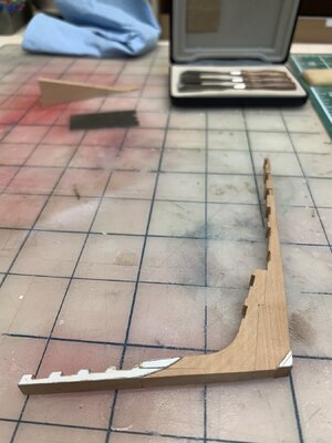
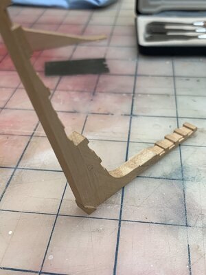
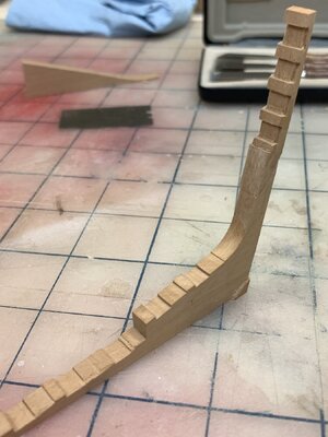
Next I had to cut the notches in the sternsom knee extension. For this I plagiarized Dieter’s (@Nersch) method for setting up the milling process. I cut the notch borders with a 0.6mm end mill and finished cutting out the notches and shoulders with a mini chisel. I think the results are acceptable.
IMG_8431.jpeg

I then moved on to tapering the sternpost knee assembly. For this I used @Tobias’ setup as he outlines here
Post in thread 'LE ROCHEFORT - Harbour yacht from 1787 1:36 by Tobias (Monograph by ANCRE)'
https://shipsofscale.com/sosforums/...y-tobias-monograph-by-ancre.10941/post-282427

IMG_8432.jpegIMG_8433.jpegIMG_8434.jpeg
IMG_8435.jpeg

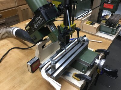
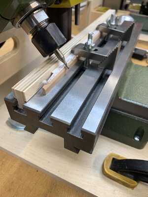
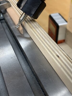
Now I need to cut the rabbit in the keel pieces and the corresponding bearding line in the rising wood. I’ve calculated to appropriate angle (42° I believe) and tilted the large mill to set up the cut.
IMG_1294.jpeg

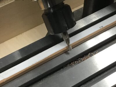
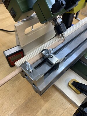
I tried it on one of my earlier failed keels but I’m not sure this is the best method. There seems to be a lot of room for things to go very badly.
IMG_1295.jpeg

The piece seems to flex in my hold down and is not making a clean cut. I need to rethink this process. I may have to break down and buy and angle vise…
Any ideas from anyone more experienced with milling?

That’s it for tonight. I need to think… and maybe have a beer!
 
Great result, Oliver. You have the option of working with a third hold-down device that you position in the middle. This means that bending along the length is no longer possible.
Thanks Tobias. I did think of adding a third (or more) hold-down but the way it’s setup there is no room behind the workpiece on the table. I tried moving the workpiece to be more centered on the table but then there is not enough travel on the “Y” axis for the cutter head to reach. I may try sliding a backstop in the groove and see if that helps. I’m also going to play with some completely different setups… we’ll see.
 
I added a “fence” backstop to the x/y table and was able to lock down the work piece without it flexing.
It worked well and the rabbit is now complete in the keel pieces.
IMG_8436.jpeg


IMG_8437.jpegIMG_8438.jpeg

Now I will assemble the axial assembly and work on carving the bearding line in the rising wood as well as the stem and stern sections.
Wish me luck.:)
 
I have now completed the keel assembly. It exactly overlays the drawing so I’m pretty happy with it. The rabbit is done along with the tapering of the stem and stern pieces. I carved the stem and sternpost with hand tools and a not so steady hand but it seems to have worked ok.
IMG_8439.jpegIMG_8440.jpegIMG_8441.jpeg
It’s now time to start cutting out and assembling the frames. I know Adrian completed the wing transom and filling pieces at this stage… I’ll have to think on that. Happy Sunday everyone!
 
Hello Oliver, you can be rightly satisfied, very good work.
Thank you Tobias for your kind support.
Do you have any thoughts on when to mount the wing transom and filling pieces. In my previous attempt I waited until the frames were installed but now wonder if the transom pieces actually help keep the keel plumb and level.
 
Back
Top