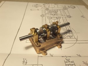
Lempi, a steam powered half open launch built in 1877 in Warkaus, Finland

Joined
Jul 27, 2018
Messages
354
Points
278

Location
Finland
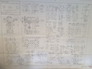
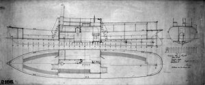
When searching something new to build, I happened to find the scanned old drawings of former Ahlstrom shipyard which was situated in Warkaus Finland. Among them was a nice drawing of a half open steam launch Lempi (almost like "love" in English) from 1877. The ship was 60 feet long and equipped with a two cylinder compound steam engine.

I had never tried to make a model with working steam engine before, so immediately when I saw the plan I decided to build a model of her. And of course with a steam engine. To get enough space in the hull for all machinery needed, I decided to build the model in 1/15 scale, ending to about 110 cm long model. So the plans were downloaded and had printed in the correct size by a professional copy shop.

Because I have rather good quality metalworking machines like lathe and a milling machine at my workshop and have already some experience to use them, I decided to try to fabricate the steam engine by myself. I wanted the engine to be two cylinder, self starting, reversing, and have a real slide valve control.
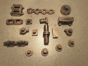
When searching from Internet suitable engines, I soon found the drawings and set of castings of an engine called Marcher with appr. 11 mm bore and stroke, which would suit well into the hull of Lempi. So the drawings and castings were purchased and project could be started.

Main drawing of Lempi:
Lempi2.jpg


Drawing of Marcher steam engine:

20180806_094651.jpg


Set of castings for Marcher:
20180816_090109.jpg
 
Thanks for your interest Uwe and Jim, and all the likes as well!

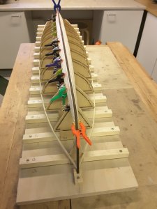
When my friends heard about my plans, they wanted to build the same model too. So we decided to build first one wooden hull with POB method and make a glassfibre mould out of it & laminate the final 3 hulls into the mould. Because I had most experience of the wooden hulls, it was decided that I will build the first one.

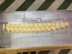
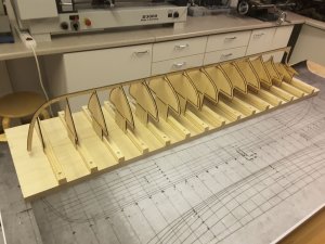
I have always wanted to try drawing the bulkheads with CAD and then cut them out with laser, so we decided to do that. Because the drawings were already scanned into electronic form, it was easy to scale them with computer into proper size and draw them on another layer with CAD. After all bulkheads were drawn, they were sent into special company to be cut with laser. This succeeded very well, and soon we had a full set of nice bulkheads cut out of 4 mm balsa plywood, and building could be started.

Laser cut bulkheads arranged on the drawing:

20180626_091850.jpg


Attached on the building board:

20180627_182811.jpg


Planking started:

20180704_082127.jpg


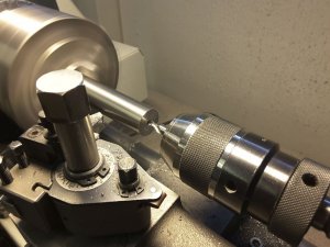
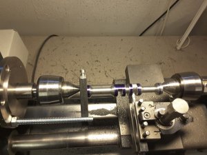
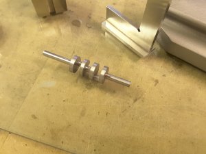
At the same time I started also building the steam engine. I wanted to start making the most difficult part first, the crankshaft. There was no casting available, so this had to be made of stock material. First I tried to make that out of several parts and glue & pin everything together, but that didn`t work, so I had to make it using solid steel. Luckily I had a piece of 20 mm round silver steel, which is a perfect material for a crankshaft. So the rod was cut in proper length, marked, centred and carefully turned in the lathe.


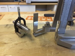
Piece of silver steel was carefully marked on both ends. Because the engine had to be self starting, the pistons and connecting rods had to have 90 degrees difference:

20180804_092610.jpg


The blank was attached into lathe and centred:

20180804_093246.jpg


And carefully turned between centres:

20180805_093337.jpg


And after a few moments careful turning the crankshaft was ready:

20180806_092516.jpg
 
Thanks Uwe! When I was still working and my retirement came closer, I intentionally invested into good machinery because I knew that when retired I don't have money enough any more for them, but free time I will have 24 hours a day for hobbies. And that has really proved to be so.
 
I am honestly speechless. I am always amazed by people who can do multiple, oftentimes independents jobs. I mean, I knew you are the craftsman, but turning on the lathe crankshaft - required learning and serious skills, as this should be proportionally precise. Bravo and huge respect!!
 
Thank you very much for your kind words Jim. After all this is no rocket science, everybody with a sturdy lathe, sharp tool and lot of patience can do the same. But speed of the lathe and feed must be very low. This is why it needs a lot of patience.
 
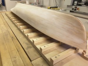
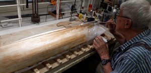
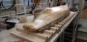
Small update: The hull was planked in a normal way. After planking it was sanded and all unevennesses were filled with a mixture of epoxy/microballoons. After that again sandin, sanding, and finally the hull was glassed with fine glassfibre & epoxy.


Hull sanded and ready for glassing:

20180714_155542.jpg


Covering the hull with glassfibre & epoxy:

20180720_131843.jpg


Glassing made:

20180720_142323.jpg


In the mean time the baseplate of the steam engine was machined. A nice gunmetal casting was provided for this. Another option was to fabricate baseplate of thick brass plate, but I liked more the casting and was using it.
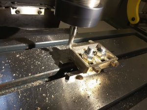
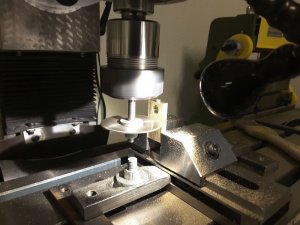
Underside was first levelled with milling machine, and after that the upper side. All the holes were marked and drilled, and finally threads were cut. Because we live in a metric country, instead of imperial threads I was using metric equivalents. Also all measurements of the parts had to be calculated from imperial to metric, because all the cutters, taps and dies which I have are metric.

Underside of the baseplate casting was levelled at the milling machine:

20180819_130738.jpg


Followed by upper side:

20180819_163938.jpg


Holes were carefully marked......

20180820_083259.jpg


......drilled and tapped:

20180823_151448.jpg


And soon we had a nice baseplate ready. Threads for columns are M3, and those for bearing blocks are M2:

20180823_153235.jpg
 
Thanks Uwe! In fact it is easy. Everything depends of careful measuring and marking. The rest is only turning handwheels of your machines.

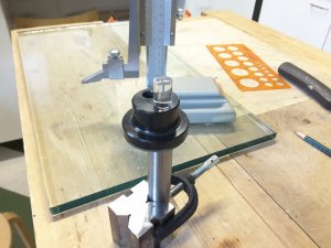
In fact, I would like to add one picture of a tool which is necessary when marking the spots for drilling and tapping: An optical centre punch. With this tool you are able to punch the starting point just spot on. I wouldn`t manage without this tool.


20180804_093727.jpg
 
Last edited:
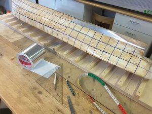
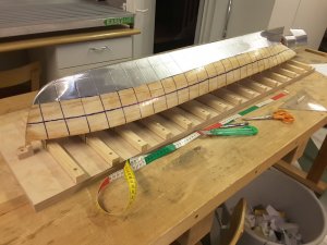
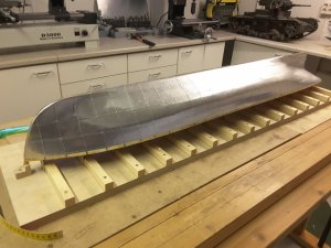
The original ship`s hull was of riveted construction and I wanted the model to look similar out. So I decided to cover the hull with aluminun plates cut from self adhering 0,1 mm thick foil.


100 mm wide foil was bought and the work could be started. Rivet rows were made using a tool made of old toy gear:

20180813_092901.jpg


20180813_160555.jpg


Soon the whole hull was covered:

20180818_091801.jpg


In the mean time building of steam engine continued. Columns to carry the cylinder block were made of 5 mm silver steel with M3 threads at both ends:

20180828_083939.jpg


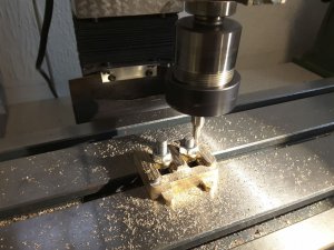
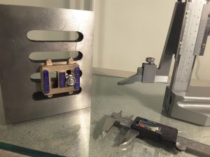
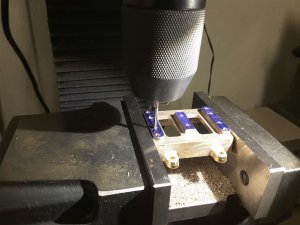
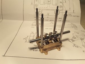
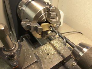
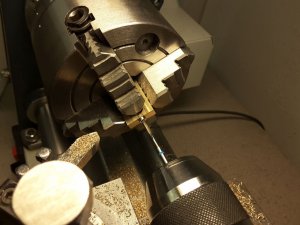
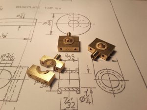
Bearing blocks for cranckshaft were made of suitable pieces of brass, by boring, reaming, and cutting threads:

20180901_130133.jpg


20180902_084551.jpg


20180902_093254.jpg


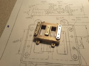
And soon all three bearing blocks were ready:

20180905_154140.jpg

20180907_093918.jpg
 
Last edited:
I haven't heard the name Lapland ( your link ) since I was a kid in the fifth grade. Lapland was where reindeer came from and we were fascinated by the snow and the deer and the clothing that was worn there. Hope you enjoy your skiing holiday and I'll surly be looking forward to the rest of your boat build when you return with all four limbs intact.:)
 
Thanks Uwe, Norgale and Knut. As we are already a bit older people than the youngsters here, we are concentrating only at cross country skiing and not the more speedy alpinist downhill. So probability to come home in one piece is very much higher.
But here we can already see the unfortunate results of the climate change: At this time of the year here should be lot of snow and temperatures around zero Celcius, but now we have a lot of sunshine, temperature around +15 celcius and hardly any snow. Very sad indeed.
 
Back
Top