Да. Вы фрезеровали их пакетом, а затем разрезали на элементы.
Yes. You milled them in a batch and then cut them into pieces.
Yes. You milled them in a batch and then cut them into pieces.
Last edited by a moderator:
 |
As a way to introduce our brass coins to the community, we will raffle off a free coin during the month of August. Follow link ABOVE for instructions for entering. |
 |
 |
The beloved Ships in Scale Magazine is back and charting a new course for 2026! Discover new skills, new techniques, and new inspirations in every issue. NOTE THAT OUR FIRST ISSUE WILL BE JAN/FEB 2026 |
 |
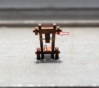
В местах пропила под оси (в щеках) не может быть 90 градусов, так как пакет был выставлен под углом и заготовка фрезеровалась под углом. Как то так!!А в том месте, где установлена ось колеса, уже не 90 градусов. Красная стрелка отмечена
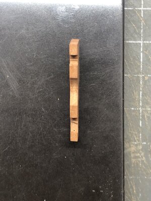
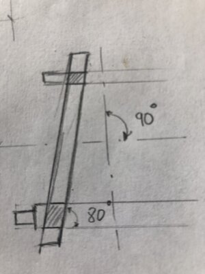
Not being able to read/understand Russian I am not able to follow the commentary above. However I would think that the splay of the carriage sides depends totally upon the proportions/diameters of the specific cannon barrel which even for the same poundage had variation depending upon where the casting was made. I think that we typically simplify this into a more regular set of dimensions. This is a very good approach to mass production though demanding upon precise machining in preparation of the long stock lengths. Well presented. Rich (PT-2)Here you milled them in a package. And then the cheeks themselves were milled again?View attachment 230593
You are correct, Rich. This is exactly a discussion about... and you said you don understand Russian?Not being able to read/understand Russian I am not able to follow the commentary above. However I would think that the splay of the carriage sides depends totally upon the proportions/diameters of the specific cannon barrel which even for the same poundage had variation depending upon where the casting was made. I think that we typically simplify this into a more regular set of dimensions. This is a very good approach to mass production though demanding upon precise machining in preparation of the long stock lengths. Well presented. Rich (PT-2)
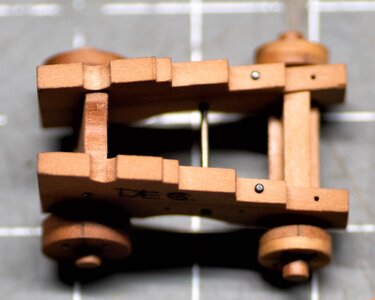
Yes, Mon Amie. It is more of my interpretation for Alert, but it is historically accurate as it represents the cartridge tonnages' for a specific barrel weight. Here, it is a DE 6. for 6 pounder barrel (I think). I just wanted to experiment with my new chisel set from Mihail Kirsanov.Is this your own interpretation.
I know on war ships of the 17th century guns did not really belonged to one single vessel but vessels were armed when prepared for battle.
This meant they had different kind of gun barrels needing different loads of gunpowder from time to time depending on what was available at the time in the armery. For this they needed references which were marked on the gun and on the cartridges meant for the gun. These references are they marked on the gun carriage? So far I wasn't able to trace this properly, but these are the details we want in our models
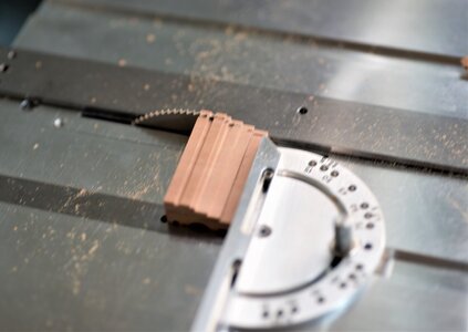
That is correct, Dan! I use the fence to set the desired thickness of 2.mm (in my case), but I set the miter gauge with the angle. The same angle I use to mill the wood stocks (left and right). Here is the view from the top. It should make better sense now.OK so if I understand correctly, you cut the sides of the wooden blocks for the carriage cheeks at the appropriate angle?
But in this picture You are using the crosscut guide to slice them off:
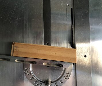
You have presented a very clear practicum on these carriages. The book The Art of Ship Modeling, Bernard Frolich, ANCRE 2002, Chapter IV Artillery, pp 134 - 154, after the preceding pages on casting of barrels, focuses on Carriages and making them, pp 147 - 49, followed by their installation. If you have or get a copy it is a "go to" for all aspects of model building. Just an idea. . . RichThat is correct, Dan! I use the fence to set the desired thickness of 2.mm (in my case), but I set the miter gauge with the angle. The same angle I use to mill the wood stocks (left and right). Here is the view from the top. It should make better sense now.
View attachment 230702
Спасибо, Джим. Теперь загадка завершенаНет, Александр. Их однажды фрезеровали. Такой вид в перспективе не дает хорошего обзора. Вот еще один вид получше. Между левым и правым блоками * посередине) деревянный шаблон (см. Стрелки).
View attachment 230595
вот еще фото
View attachment 230597
Thanks, Rich. I am the proud owner of this book, and it is my primer for most of my work! If you want to learn something, you better do it from wise guys!You have presented a very clear practicum on these carriages. The book The Art of Ship Modeling, Bernard Frolich, ANCRE 2002, Chapter IV Artillery, pp 134 - 154, after the preceding pages on casting of barrels, focuses on Carriages and making them, pp 147 - 49, followed by their installation. If you have or get a copy it is a "go to" for all aspects of model building. Just an idea. . . Rich
Спасибо Александр, можно просто, Дима.Спасибо, Джим. Теперь загадка завершенаНедурно
I am going to follow his recommendations on sail making for my BN and not fold the fabric over taking it out of scale. My hesitancy is in how to stabilize the fabric to accurately draw the sewing lines without fouling the sewing machine. . . open dock for recommendations on this one. RichThanks, Rich. I am the proud owner of this book, and it is my primer for most of my work! If you want to learn something, you better do it from wise guys!
