-

Win a Free Custom Engraved Brass Coin!!!
As a way to introduce our brass coins to the community, we will raffle off a free coin during the month of August. Follow link ABOVE for instructions for entering.
-

PRE-ORDER SHIPS IN SCALE TODAY!
The beloved Ships in Scale Magazine is back and charting a new course for 2026!
Discover new skills, new techniques, and new inspirations in every issue.
NOTE THAT OUR FIRST ISSUE WILL BE JAN/FEB 2026
You are using an out of date browser. It may not display this or other websites correctly.
You should upgrade or use an alternative browser.
You should upgrade or use an alternative browser.
Making trucks for your cannon carriages
- Thread starter Jimsky
- Start date
- Watchers 22
-
- Tags
- cannon truck wheels
Yes, it is a great quality set made professionally by Mihail.Great set.
I am very happy for you that you received now also a set from Mihail...... they are great.Today is 'My gift day' after two months of traveling from Russia (ouch), I got my miniature\carving chisels courtesy of Mihail Kirsanov.
View attachment 229335
I couldn't resist trying them out and made some tests. Here is the result.
View attachment 229336
View attachment 229337
I am very happy with my set since some years....... the only problem is to keep them also in future sharp like hell (like they are now)
BTW- this is my set
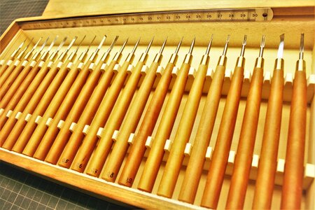
I guess we are some of the many happy guys owning this great toolset. Those miniatures chisels are very good quality. As for the sharpening\honning Mihail provided a manual. Do you need one, I can give it to you? I suspect, the chisels will require honing most of the time, unless the chisel broke, then you will need sharpening.I am very happy for you that you received now also a set from Mihail...... they are great.
I am very happy with my set since some years....... the only problem is to keep them also in future sharp like hell (like they are now)
BTW- this is my set
This would be great, if you can send this manual to me. At the time I bought, it was not included.......I guess we are some of the many happy guys owning this great toolset. Those miniatures chisels are very good quality. As for the sharpening\honning Mihail provided a manual. Do you need one, I can give it to you? I suspect, the chisels will require honing most of the time, unless the chisel broke, then you will need sharpening.
Here you go Uwe and anyone needs it. Let me know if the process understandable enough. I think Mihail uses some cert of available online translators.This would be great, if you can send this manual to me. At the time I bought, it was not included.......
Attachments
Greetings all! I saw that the trucks tutorial get interested for many members so I decided to continue with the tutorial of making naval cannons (the way I do).  Today's topic is cannon carriages. Well, I found that making the carriages is time-consuming and becomes a burden in repetition, specifically if you have to make them for a three-decker.
  But even for Alert, I am assembling, 12 cannons are quite enough to get bored with the redundant tasks. The problem, however, that all those cannons are in the upper deck and will be exposed to the viewer's eyes. They must be presentable and somewhat identical. This might not be necessary the way, your carriages should be built, but I like this method, and I would like to share it with you.
As mentioned above, the cartridges will be built for an Alert. There will be mostly photos as they are self-explanatory, but I will notate the process as it goes. Lets' begin. I choose Pearwood for brackets (sides), and now kinda in doubt whether the final color after oil will match the cherry hull to make a nice harmony. But I will deal with it later... 12 cannons are 24 brackets. Making 24 brackets individually - is a crazy idea and overkill. The solution was found to make a solid block with milled brackets steps, groves for both front and rear axletrees' and a grove for trunion. After the entire block ready, just slice for ready brackets. They will be pretty identical.
Part1, making the brackets
Brackets consist of two parts, they were cut on a table saw, and the top part blackened with HB pencil to create a nice separation line
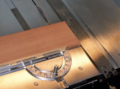
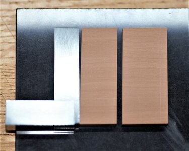
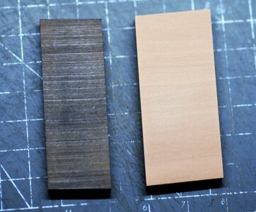
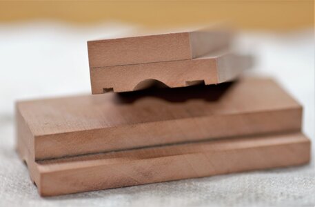
Some of my earlier photos were lost, they were accidentally deleted (for good) without a recovery option. I will borrow some later images to show the current discussion. The below photo will show the blocks after gluing. Just look at the bottom one to get an idea of how it should look.
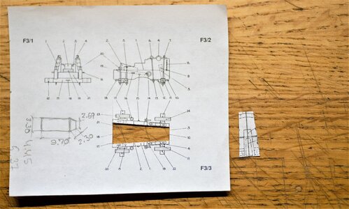
Both blocks: left and right were installed on the jig made specifically for this type of job. I use double-sided sticky tape, It is very thin and holds strong. Pay attention to the wooden block in the middle of the jig. This piece is really important when milling all the steps and groves as they have to be at a specific angle. This block was made by using the drawing from the AOTS book. First I downgrade the scale to 1:48, printed and cut it out.
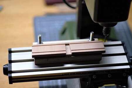
The first task to mill the front and rear (hind) axletree groves. The rear grove 4.00mm wide and the front 2,5mm. This required straight flute mills (3.00 and 2.5mm)
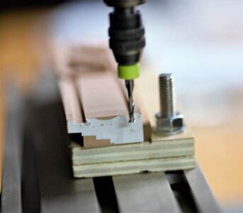
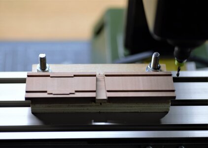
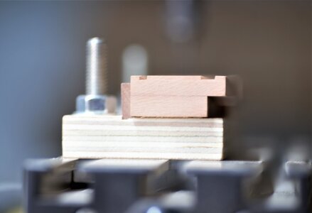
The next task is to mill the middle of the brackets, For this job, I used round (ball) bur. Frankly, it doesn't design for use in the milling machine so it took a while until I get the acceptable result. You must remove a very tinny layer in one path to avoid wood-burning.
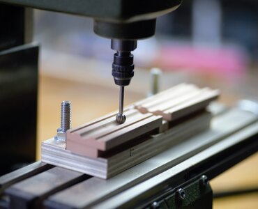
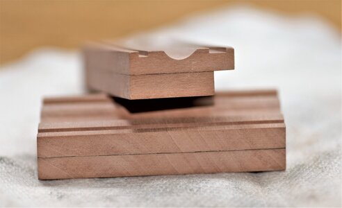
Once I satisfy with the results, I turned the blocks upside down using a new double-sided tape. Now, we will mill all brackets steps and the trunnion grove. For the steps milling, I used the same straight flute endmill (about 3.1mm), and for the trunnion grove the small 2,5mm round bur.
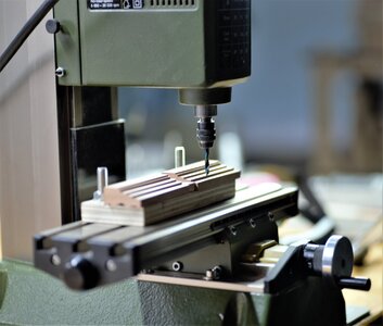
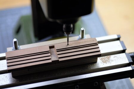
To check the proper angle and the trunnion grove I fit a cannon barrel and was quite happy with the test result.
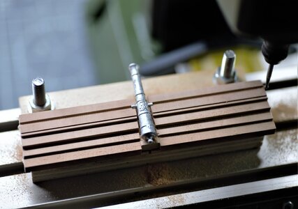
Milled blocks from both sides should look like on the images below.
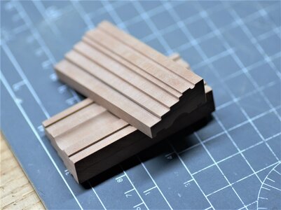
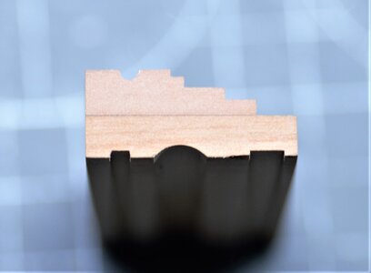
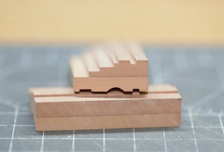
Now, we came to the rewarding part. Assuming that the milling job is done accurately, we will slice the blocks on the tablesaw to make actual brackets, and they should be identical!! Mission accomplished!
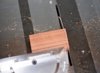
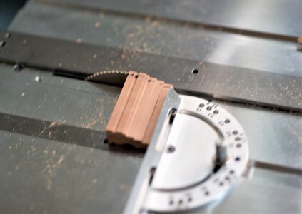
...and here you go!!!!
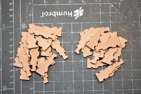
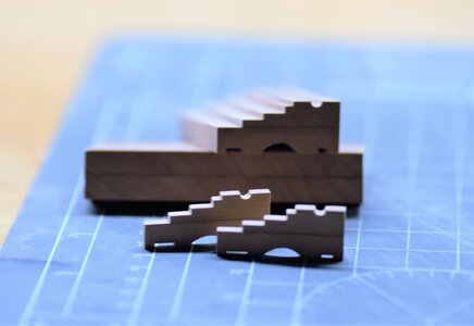
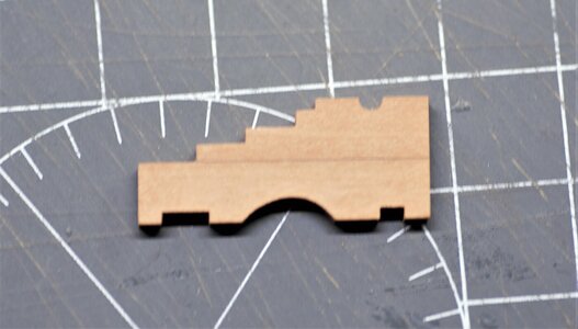
Well...this is the most difficult part and requires close attention and precision measurement. Remember, if you made a mistake, all the brackets will have this mistake. The rest of the tasks should be more fun.
Part 2, working with brackets
The next step is to make the holes for the bolts in both left and right brackets. Looks like a huge and time-consuming task making 144 holes. Here is comes another jig, just for this task. Here I use another set of blocks glued with the angle. Again the shape of the blocks determined by folding in the middle of the cut-out pattern used in Part 1.
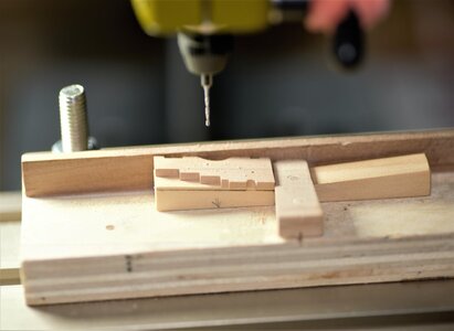
I hope you get an idea why this angle is very important. Also, the wooden blocks are fixed with double sticky tape. I left the gap between the vertical side of the jig and those blocks. The size of the gap is the width of the bracket and will serve as a conductor when drilling holes for vertical bolts.
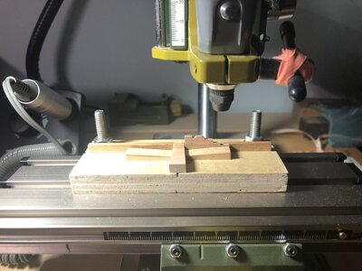
After some time drilling, you will have left and right brackets ready for assembly.
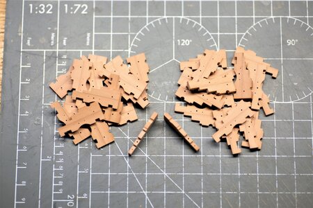

Alright, folks, we will continue with the assembly tomorrow. There will be more images and explanations... Please let me know if you have any questions and need to elaborate. Thank you!
As mentioned above, the cartridges will be built for an Alert. There will be mostly photos as they are self-explanatory, but I will notate the process as it goes. Lets' begin. I choose Pearwood for brackets (sides), and now kinda in doubt whether the final color after oil will match the cherry hull to make a nice harmony. But I will deal with it later... 12 cannons are 24 brackets. Making 24 brackets individually - is a crazy idea and overkill. The solution was found to make a solid block with milled brackets steps, groves for both front and rear axletrees' and a grove for trunion. After the entire block ready, just slice for ready brackets. They will be pretty identical.
Part1, making the brackets
Brackets consist of two parts, they were cut on a table saw, and the top part blackened with HB pencil to create a nice separation line


Some of my earlier photos were lost, they were accidentally deleted (for good) without a recovery option. I will borrow some later images to show the current discussion. The below photo will show the blocks after gluing. Just look at the bottom one to get an idea of how it should look.

Both blocks: left and right were installed on the jig made specifically for this type of job. I use double-sided sticky tape, It is very thin and holds strong. Pay attention to the wooden block in the middle of the jig. This piece is really important when milling all the steps and groves as they have to be at a specific angle. This block was made by using the drawing from the AOTS book. First I downgrade the scale to 1:48, printed and cut it out.

The first task to mill the front and rear (hind) axletree groves. The rear grove 4.00mm wide and the front 2,5mm. This required straight flute mills (3.00 and 2.5mm)


The next task is to mill the middle of the brackets, For this job, I used round (ball) bur. Frankly, it doesn't design for use in the milling machine so it took a while until I get the acceptable result. You must remove a very tinny layer in one path to avoid wood-burning.


Once I satisfy with the results, I turned the blocks upside down using a new double-sided tape. Now, we will mill all brackets steps and the trunnion grove. For the steps milling, I used the same straight flute endmill (about 3.1mm), and for the trunnion grove the small 2,5mm round bur.


To check the proper angle and the trunnion grove I fit a cannon barrel and was quite happy with the test result.

Milled blocks from both sides should look like on the images below.


Now, we came to the rewarding part. Assuming that the milling job is done accurately, we will slice the blocks on the tablesaw to make actual brackets, and they should be identical!! Mission accomplished!


...and here you go!!!!


Well...this is the most difficult part and requires close attention and precision measurement. Remember, if you made a mistake, all the brackets will have this mistake. The rest of the tasks should be more fun.
Part 2, working with brackets
The next step is to make the holes for the bolts in both left and right brackets. Looks like a huge and time-consuming task making 144 holes. Here is comes another jig, just for this task. Here I use another set of blocks glued with the angle. Again the shape of the blocks determined by folding in the middle of the cut-out pattern used in Part 1.

I hope you get an idea why this angle is very important. Also, the wooden blocks are fixed with double sticky tape. I left the gap between the vertical side of the jig and those blocks. The size of the gap is the width of the bracket and will serve as a conductor when drilling holes for vertical bolts.

After some time drilling, you will have left and right brackets ready for assembly.


Alright, folks, we will continue with the assembly tomorrow. There will be more images and explanations... Please let me know if you have any questions and need to elaborate. Thank you!
Very nice machining method. I have found that "dowels" are just that and typically not round but irregular. On my own cannons I took some copper pipe cut sections and drove them over the dowel, cut them to desired width, and used livers of Sulphur to blacken the outer copper rims. It produced a truck that I was satisfied with as not trying to be historically precise as they were not intended for a model. The cutting and drilling jigs and drill press make a very nice truck.. Well done' Richcontinue from the previous post...
Then, I flatten by sanding the tops and rounded using the rotary tool. Here, on the right, you can see I use a copper wire.
View attachment 226159View attachment 226160
I made a small video to depict the rounding process and hope you will have an idea.
...and the final product, the trucks I will use for my Alert build.
The Naval Cutter ALERT- 1777, POF by Jimsky
Great news, folks!! Today July 27th, 2020, I have purchased the Trident Model Alert kit! The purchase experience was pleasant, straight forward, without hiccups, and took about 3~5 minutes. With this great news, I am officially joining the Alert group build and starting my own build log. When...shipsofscale.com
View attachment 226161
Here are the front trucks. Some of them are darker colors, I experimented with oil. Of cause, I use Linseed oil, you guessed it right!
View attachment 226162
and the rear trucks.
View attachment 226163
The tools I made and used.
View attachment 226164
Just to have an idea of what you can do with your trucks, should you choose to accept it... on the bellow image, top left is @ Maarten style, which he uses on his Alert build
Hms Alert by Maarten [COMPLETED BUILD]
Yeah my kit came in after exactly 30 days shipping and customs. I had to pay €46,- for VAT and customs clearing but it is well worth it for a box full of goodies. I will build it next to my RC and already have some ideas of what I will do with it. It won't be a straight out of the box build but...shipsofscale.com
View attachment 226165
Well...that's it, folks. I hope this was informative and you will find it useful. If you have any questions, please let me know... Thank you!!
Your method, Rich is just as good as others. Frankly, any methods that you incorporate and accept are good. There are many other methods to round the wooden dowels, and they well...will require some machining.Very nice machining method. I have found that "dowels" are just that and typically not round but irregular. On my own cannons I took some copper pipe cut sections and drove them over the dowel, cut them to desired width, and used livers of Sulphur to blacken the outer copper rims. It produced a truck that I was satisfied with as not trying to be historically precise as they were not intended for a model. The cutting and drilling jigs and drill press make a very nice truck.. Well done' Rich
Thank you, Dan. I think it is a very good approach\method but it does require a milling machine. Before I have had the milling machine I use the table saw, with the same results, it took a bit more time but the results were the same.Nice!! Looks just so clean!
This is how I made my carriages for my Cruiser Several years ago. But I didn't think of the drilling jig to drill the angled holes so thank You for showing!!
Many thanks for your 'likes and interest in this topic. Today we will continue making our cannon carriages and discuss assembly.
Part3 making the axletrees'
It is not obvious, but some cannons required weels, the more common names known as 'trucks'. We already discussed the making of trucks in the previous posts, so we will make just the axletree for both front and rear trucks. We have to find out the axle diameter to prepare the stock of wood. The front axletree is pretty simple and should be prepared with the required height size before sliced for needed pieces. The 'hind' (rear) axletree is fancy and will require some interesting work.
From the photo below you will see what I mean. It is not a square and requires some milling. You can use a milling machine, but this time I will use just a table saw. I think this way you can achieve better results. The saw blade height must be set this way so when you cut from both sides it is formed the square stock the size of an axle. The fence must be set for the length of the axle. This way, you can process both ends with one setup (see below).
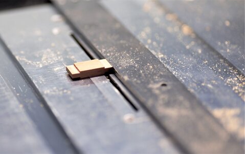
It is a good idea to check the recess for the axletrees fitment in the brackets we made in the previous post.
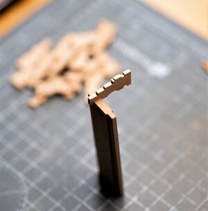
Now, we can safely make both axletrees' by slicing the same way we slice sides. Just set the fence for the required size.
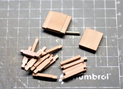
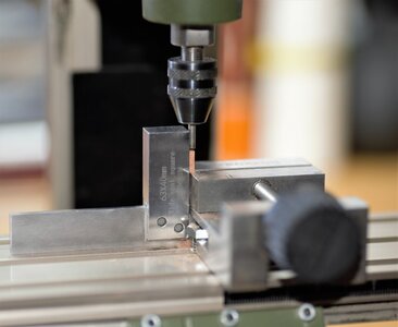
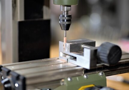
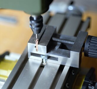
Hard to imagine that trucks will turn freely on the square axle As you can guess we have to round. For the next step, we will use a piece of steel tubing. The challenge, however, to find a suitable size. I am one of those who collect everything in mind it may be used in the future. Luckily, I found an old telescopic antenna from a super-old shortwave radio. One of the small links' internal diameter matches the hole diameter on my trucks. Yay!!! The cutting end must be shaped with a few notches thru to make a cutting edge. Then you will use it like a drill bit. One more thing, on the front axletree, you must make some notches so you will identify the size of the axle.
First set the parts with a machinist square
then, pretend you are drilling the hole...
and here is the result.
Macro view (I love macros!!!!)
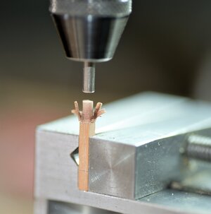
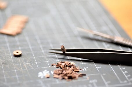
Here you got rewarded with a perfect round axle. Cannot resist trying the truck fits
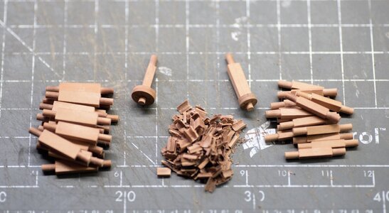
With the making of axletrees', I think, we are ready for the carriage assembly
Part 4, assembly
For the assembly, we will need yet another jig. Frankly, it is not a necessity but it should make the assembly process uniform. Remember, the cannons must be lined up and looks the same
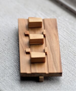
I will not describe the make of the jig as the images will speak for themselves. Below, is the back of this jig. The bar was necessary for me to mill the grooves as my mill vise doesn't open wide enough, so I use to hold the jig by this bar in the vise.
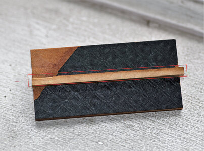
Here is the front of the jig. Using this jig, I can assemble three carriages in a time.
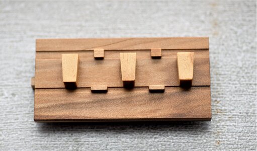
Again, the importance of the wooden blocks They made using the same cutout template we utilized when milling the sides, those blocks are formers for the carriages. The small spacers and grooves are locations to position axletrees (front and rear). The entire surface was treated with few coats of oil. This should protect from accidental gluing to the jig parts.

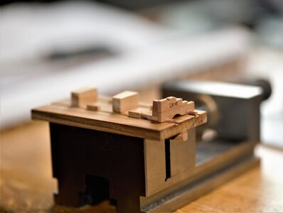
Now the assembly process. Note, I am tight the jig in my toolmakers' vise. They are heavy enough to hold the jig in place while working. Good idea!
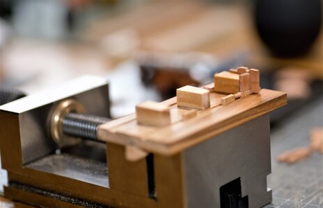
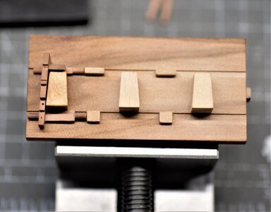
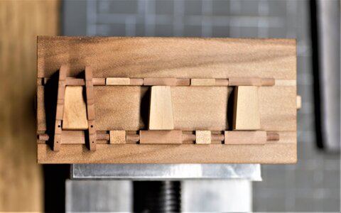
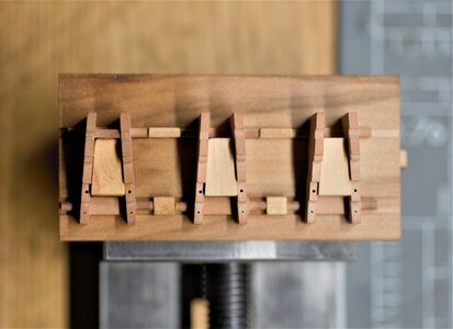
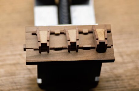
There are few parts of the carriage assembly I couldn't make in a batch, they are transom and bolster. Both of them need bevels from both sides in order to fit snag. However, I did prepare the wood stock, and yet another jig to cut the Bolster. Another part of the assembly is the 'Stool Bed', which required some milling work and can be produced in a batch.
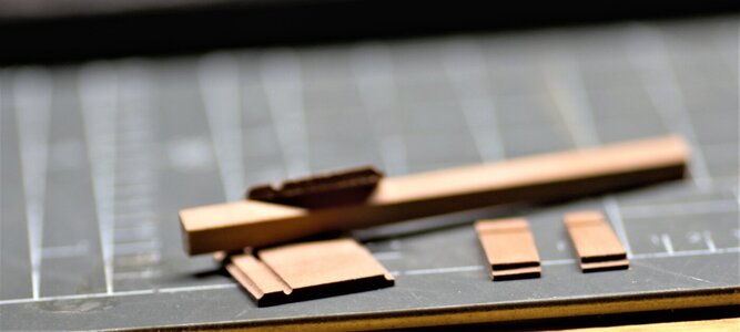
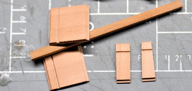
Here is the gig to cut the Bolster
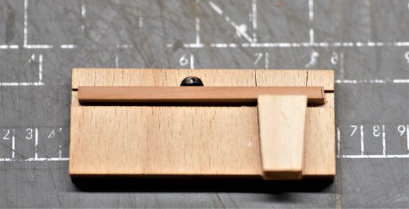
will continue on the next post with photos of the fully assembled cartridge.
Part3 making the axletrees'
It is not obvious, but some cannons required weels, the more common names known as 'trucks'. We already discussed the making of trucks in the previous posts, so we will make just the axletree for both front and rear trucks. We have to find out the axle diameter to prepare the stock of wood. The front axletree is pretty simple and should be prepared with the required height size before sliced for needed pieces. The 'hind' (rear) axletree is fancy and will require some interesting work.
From the photo below you will see what I mean. It is not a square and requires some milling. You can use a milling machine, but this time I will use just a table saw. I think this way you can achieve better results. The saw blade height must be set this way so when you cut from both sides it is formed the square stock the size of an axle. The fence must be set for the length of the axle. This way, you can process both ends with one setup (see below).

It is a good idea to check the recess for the axletrees fitment in the brackets we made in the previous post.

Now, we can safely make both axletrees' by slicing the same way we slice sides. Just set the fence for the required size.

Hard to imagine that trucks will turn freely on the square axle
First set the parts with a machinist square

then, pretend you are drilling the hole...

and here is the result.

Macro view (I love macros!!!!)


Here you got rewarded with a perfect round axle. Cannot resist trying the truck fits

With the making of axletrees', I think, we are ready for the carriage assembly
Part 4, assembly
For the assembly, we will need yet another jig. Frankly, it is not a necessity but it should make the assembly process uniform. Remember, the cannons must be lined up and looks the same
I will not describe the make of the jig as the images will speak for themselves. Below, is the back of this jig. The bar was necessary for me to mill the grooves as my mill vise doesn't open wide enough, so I use to hold the jig by this bar in the vise.

Here is the front of the jig. Using this jig, I can assemble three carriages in a time.

Again, the importance of the wooden blocks
 They made using the same cutout template we utilized when milling the sides, those blocks are formers for the carriages. The small spacers and grooves are locations to position axletrees (front and rear). The entire surface was treated with few coats of oil. This should protect from accidental gluing to the jig parts.


Now the assembly process. Note, I am tight the jig in my toolmakers' vise. They are heavy enough to hold the jig in place while working. Good idea!


There are few parts of the carriage assembly I couldn't make in a batch, they are transom and bolster. Both of them need bevels from both sides in order to fit snag. However, I did prepare the wood stock, and yet another jig to cut the Bolster. Another part of the assembly is the 'Stool Bed', which required some milling work and can be produced in a batch.


Here is the gig to cut the Bolster

will continue on the next post with photos of the fully assembled cartridge.
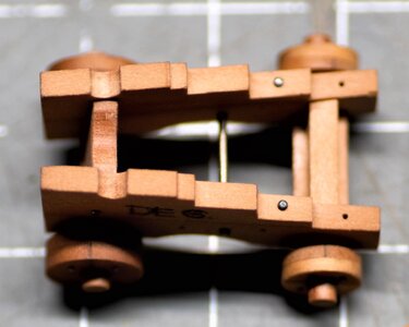
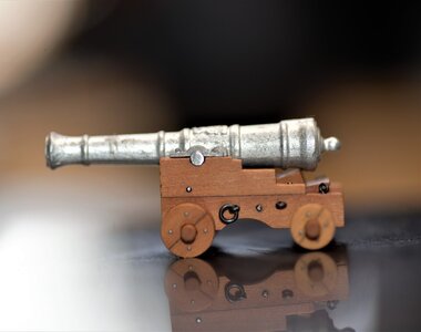
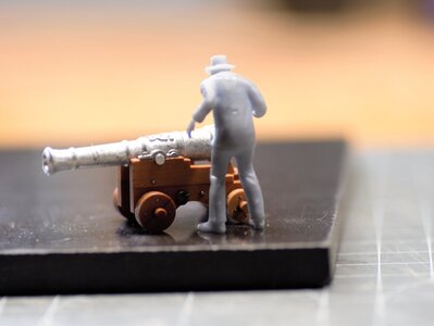
...and here are the assembled cartridge from different angles
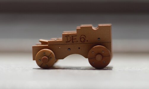

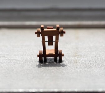
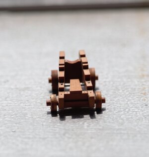
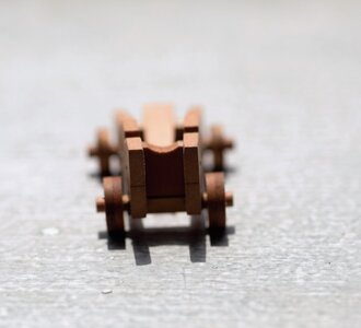
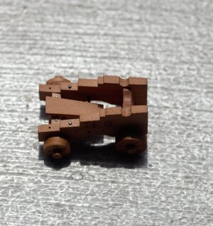
The supervisor put the barrel to check the alignments and fitting. I guess he was satisfied with the current status, But I definitely do!
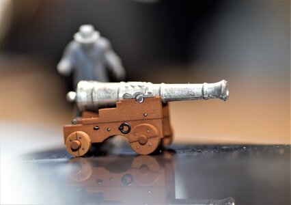
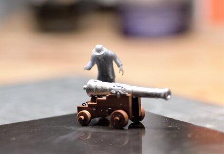

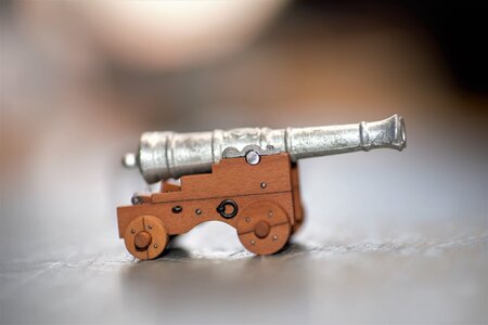
Well...there is not much left. Drill the hole for the Linch Pins and make the pins. Thank you for your interest, and please, if you are not sure what the process is, I'd like your questions\comments.


The supervisor put the barrel to check the alignments and fitting. I guess he was satisfied with the current status, But I definitely do!


Well...there is not much left. Drill the hole for the Linch Pins and make the pins. Thank you for your interest, and please, if you are not sure what the process is, I'd like your questions\comments.
Excellent work Jim, knowings the size of these they are as sharp as a razor blade, so much better then the cherry ones.
Джим, привет. У меня такой вопрос: я не понял здесь, в этом месте... а вот и собранный патрон с разных ракурсов
View attachment 230541
View attachment 230542
View attachment 230543
View attachment 230544
View attachment 230545
View attachment 230546
View attachment 230550
Супервайзер поставил ствол, чтобы проверить соосность и подгонку. Думаю, он был доволен текущим статусом, но я определенно доволен!
View attachment 230552
View attachment 230553
View attachment 230554
View attachment 230555
View attachment 230557
View attachment 230558
Ну ... осталось не так уж много. Просверлите отверстие для штифтов и сделайте штифты. Спасибо за проявленный интерес, и, пожалуйста, если вы не уверены в том, что это за процесс, я хотел бы получить ваши вопросы \ комментарии.
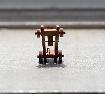
Jim, hi. I have a question like this: I did not understand here in this place
Last edited by a moderator:
Когда щеки лафета были изготовлены, их разрезали под углом 90 градусов. А оси колес выставлены под другим углом, потому что щеки слегка повернуты. Сиденья для осей стачивали?
When the carriage cheeks were made, they were cut at a 90 degree angle. And the wheel axles are set at a different angle because the cheeks are slightly turned. Did you grind the axle seats?
When the carriage cheeks were made, they were cut at a 90 degree angle. And the wheel axles are set at a different angle because the cheeks are slightly turned. Did you grind the axle seats?
Last edited by a moderator:
Thank you, my friend! The cherry ones, the cherry one is decent quality and make an acceptable quality out of the box. But hey...who said we cannot make our own?Excellent work Jim, knowings the size of these they are as sharp as a razor blade, so much better then the cherry ones.
Приветствую Александр,Когда щеки лафета были изготовлены, их разрезали под углом 90 градусов. А оси колес выставлены под другим углом, потому что щеки слегка повернуты. Сиденья для осей стачивали?
Щеки лафетов фрезеровались в блоке под углом установленным шаблоном с чертежа, под этим же углом распиливались на отдельные щеки. По этому катки параллельны центральной оси лафетов.
Не совсем понятно о сиденьях для осей. В щеках есть пазы для осей. Я правильно понял?
Greetings Alexander,
The cheeks of the carriages were milled in a block at an angle using a template set from the drawing, and at the same angle they were sawn into separate cheeks. Therefore, the rollers are parallel to the central axis of the carriages.
Not entirely clear about axle seats. The cheeks have grooves for the axles. Did I understand correctly?
Last edited by a moderator:


