-

Win a Free Custom Engraved Brass Coin!!!
As a way to introduce our brass coins to the community, we will raffle off a free coin during the month of August. Follow link ABOVE for instructions for entering.
-

PRE-ORDER SHIPS IN SCALE TODAY!
The beloved Ships in Scale Magazine is back and charting a new course for 2026!
Discover new skills, new techniques, and new inspirations in every issue.
NOTE THAT OUR FIRST ISSUE WILL BE JAN/FEB 2026
- Home
- Forums
- Ships of Scale Build Logs
- Super Detailing Static Models / Other Genres
- Historical Trailways, Guns, Aircraft, and Cars
You are using an out of date browser. It may not display this or other websites correctly.
You should upgrade or use an alternative browser.
You should upgrade or use an alternative browser.
Thanks Rick, it took me from August 2005 (brought home a pile of parts) to january 2007 (took my first test drive after a full resto).
Hallo @FrançoisHi all,
I finaly started my next project. As mentionned in my Pocher Rolls Royce restoration wip, I wanted to transform the Rolls into the Hydra Coupe. But the Rolls being a 1/8 scale model, the would make the Hydra at over 36 inches long. A bit much. So I decided to leave the Rolls and it's restoration for later and will be making the Hydra in a more reasonable 1/12 scale. A scale that I know and like very much. It will still be a huge model at a little over 24 inches long and 8 inches wide. But it should be more manageable. Another plus is that I can use some parts from my bentley project as references since it's also 1/12.
This model will be 100% scratch built or rather 3d printed. Some aluminium and brass will be used here and there along with leather for the seats but otherwise, it will be made of printable resin.
Like on the Bentley, I would like to have a working engine and drive train. The difficulty will be to find the info since this car doesn't really exist other then as a movie prop. All I have are a few pictures. I also know that the rear drive train is based on the 1940 (or about) Mercedes G4. I did find some info on that. But otherwise, I'll be using some major 'modelers leeway ' to create most parts. I don't intent to do as much details as I did on the Bentley but, then again, I might get carried away.
So the first step is to design the 3d model before printing anything. So far, I've got the tires and wheels done plus I started the rear drive. Being a 6 wheeler, it has 2 differentiels and 2 drive shafts. Plus a pretty funky suspension system.
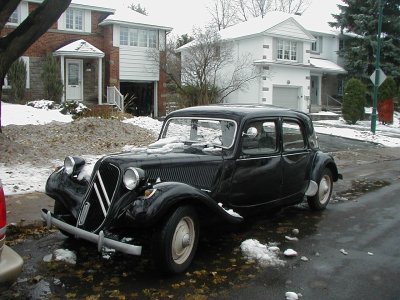
For those of you that have no idea what the Hydra coupe is and as a reminder for the others, here's what I'm aiming for
Here's the G4 drive train
and here's what been done so far
boy, do l have a long ways to go!
we wish you all the BEST and a HAPPY BIRTHDAY

Also from my side a Happy Birthday, François. Enjoy this day.
Regards, Peter
Regards, Peter
I was hoping for some advice. I have worked with material removal for about 35 years. And so I know how to design and have things milled and drilled. But I am new to additive stuff. I was not a big fan of filament tech but am intrigued about resins. Is there something you would point someone like me to for learning more about this tech?
M.
M.
Mondrasek, I'm also from the material removal school and the transition to designing for 3d printing was very easy. So far, very few parts I've designed could not be printed. Just remember to never design something with an inner cavity that can't drain (the resin is liquid and will not cure if it's in an inclosed area. The major trick to 3d printing lies in the way you orient and support the part. You also need to control your environment ( temp, air evacuation...). Once you get the hang of it, you will soon see that wire printing is no match to resin. Hope this helps!
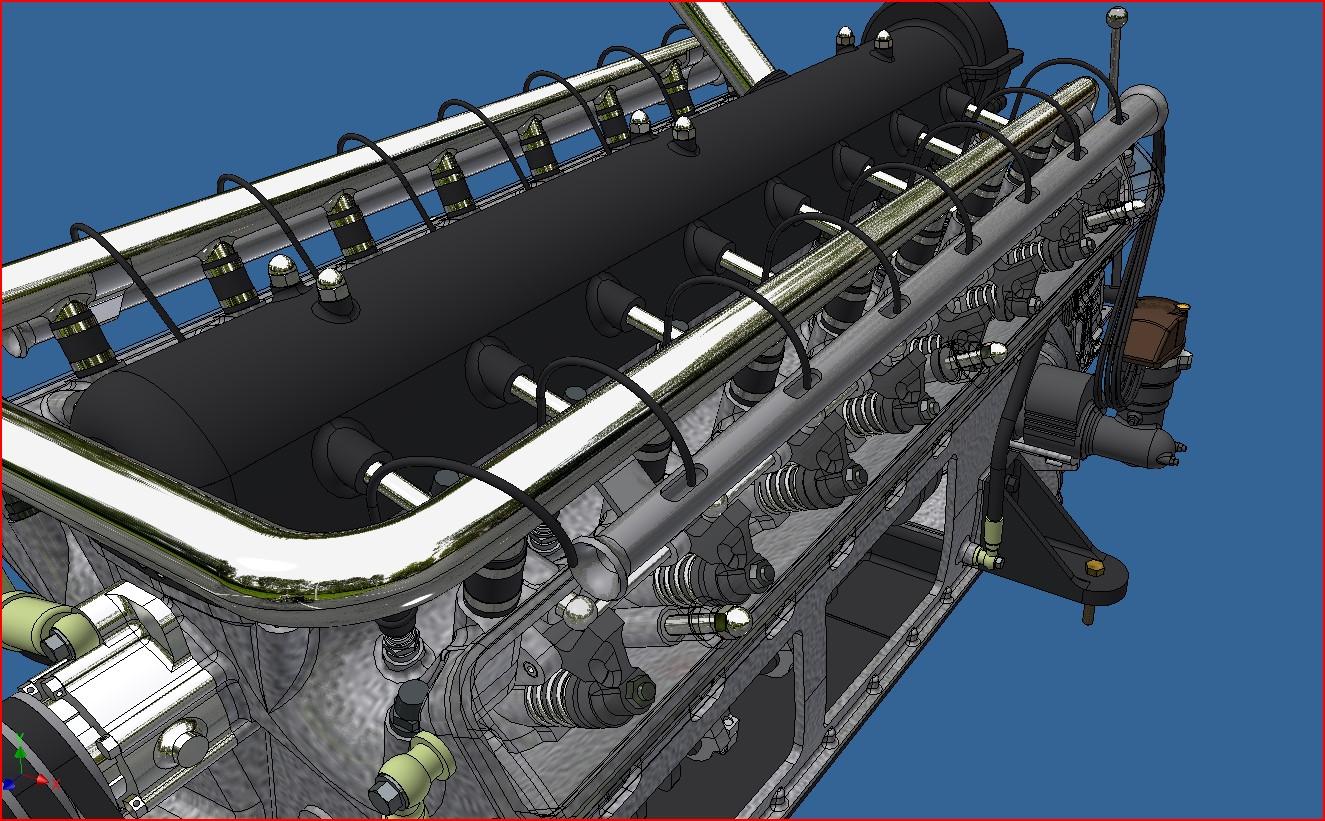
Did a bit more work on the motor's 3d model. Fan is in place, waterpump, cooling pipes and front motor mounts. Here are a few screen shots.
Motor

And motor in frame

Motor

And motor in frame

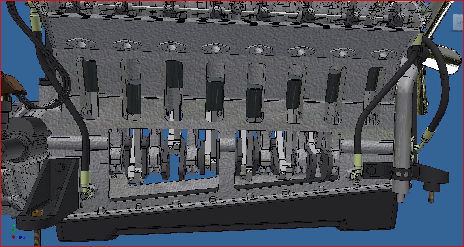
Pretty much done with the design of the engine. I incorporated some viewing windows in the block so the crank and pistons can be seen. I should start printing soon. I'll also make a base to mount it on once completed while I do the frame.






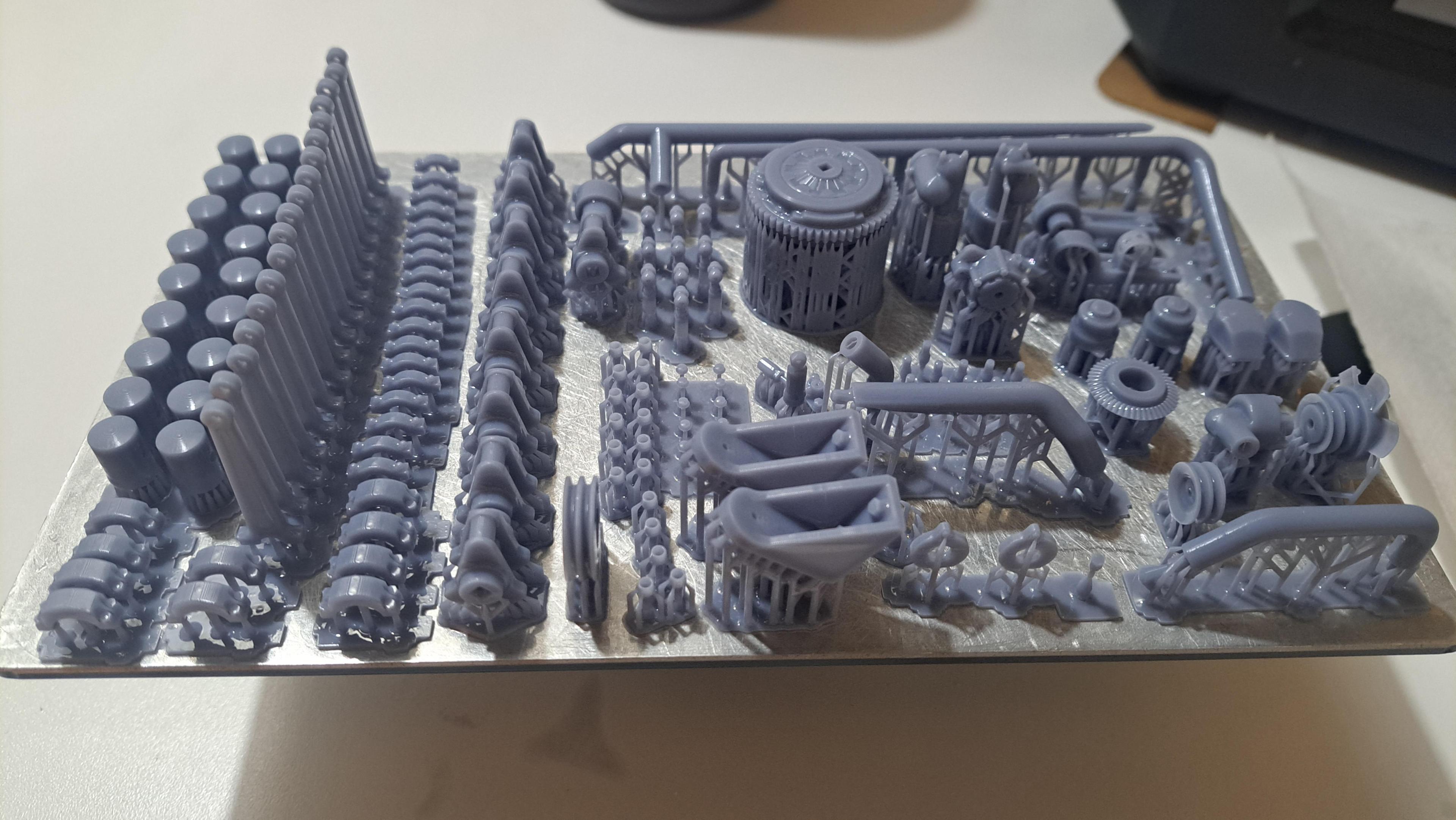
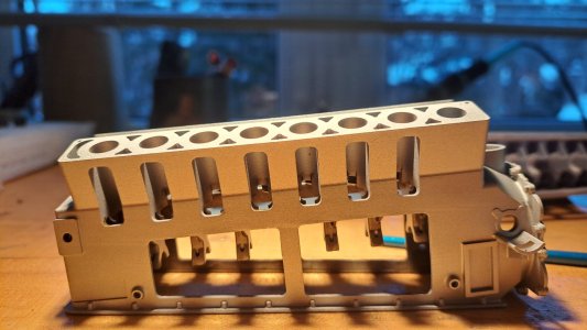
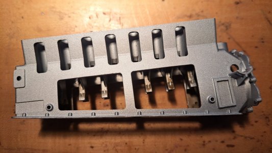
I printed the engine bloc. The first try was a partiel success (about 70% good). I printed this part in a vertical position (crank shaft axis vertical) thinking this was the best position, not so good after all. The top portion, where the head sits, wasn't totaly formed and the crank shaft support didn't print. All other features and mounting points/surfaces were ok. For the second try, I printed in a horizontal position (crank shaft axis horizontal) and I had about the same success rate. But on this one the top portion was perfect, the head sits nicely but it's the lower portion that didn't make it. The flange where the sump cover mates barely printed and the crank shaft support didn't print. For the third try, I still printed in a horizontal position but I redid the majority of the print supports. The print has just completed and is still dripping so it's hard to see but it looks promissing.
First try


With sump cover in place

With the second try, hge head sits nicely but bottom flange is a mess


Third try fresh off the printer, still dripping and full of supports but it looks good.

Test print of 1 of 16 exhaust pipes, looks ok.

First try


With sump cover in place

With the second try, hge head sits nicely but bottom flange is a mess


Third try fresh off the printer, still dripping and full of supports but it looks good.

Test print of 1 of 16 exhaust pipes, looks ok.

All the parts for the engine are printed (and being a V16, there's a lot of parts!) And most are painted. I still need to do a bit of weathering, a bit of oil here and there but nothing too fancy. It took me 4 tries to print the bloc but the 4th one is flawless.
Here are some pictures.
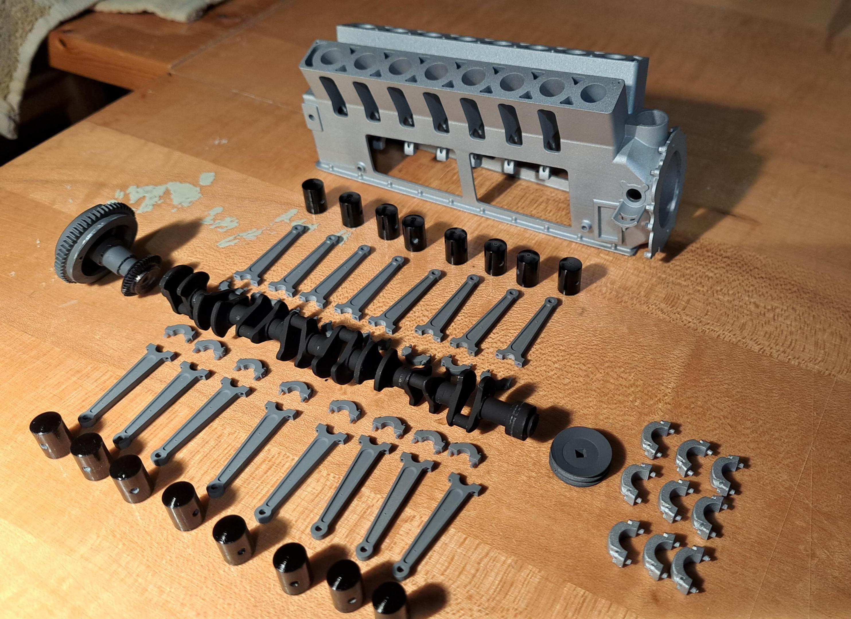
Lower engine components
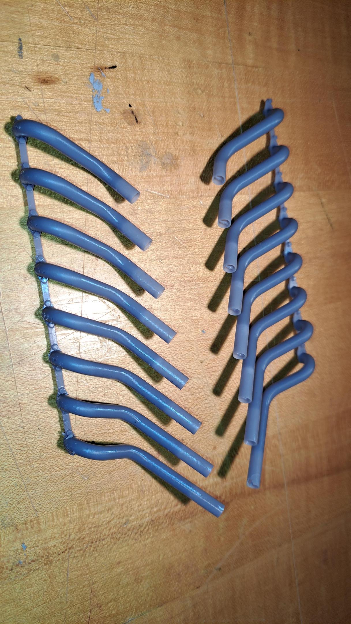
Exhaust (not painted)
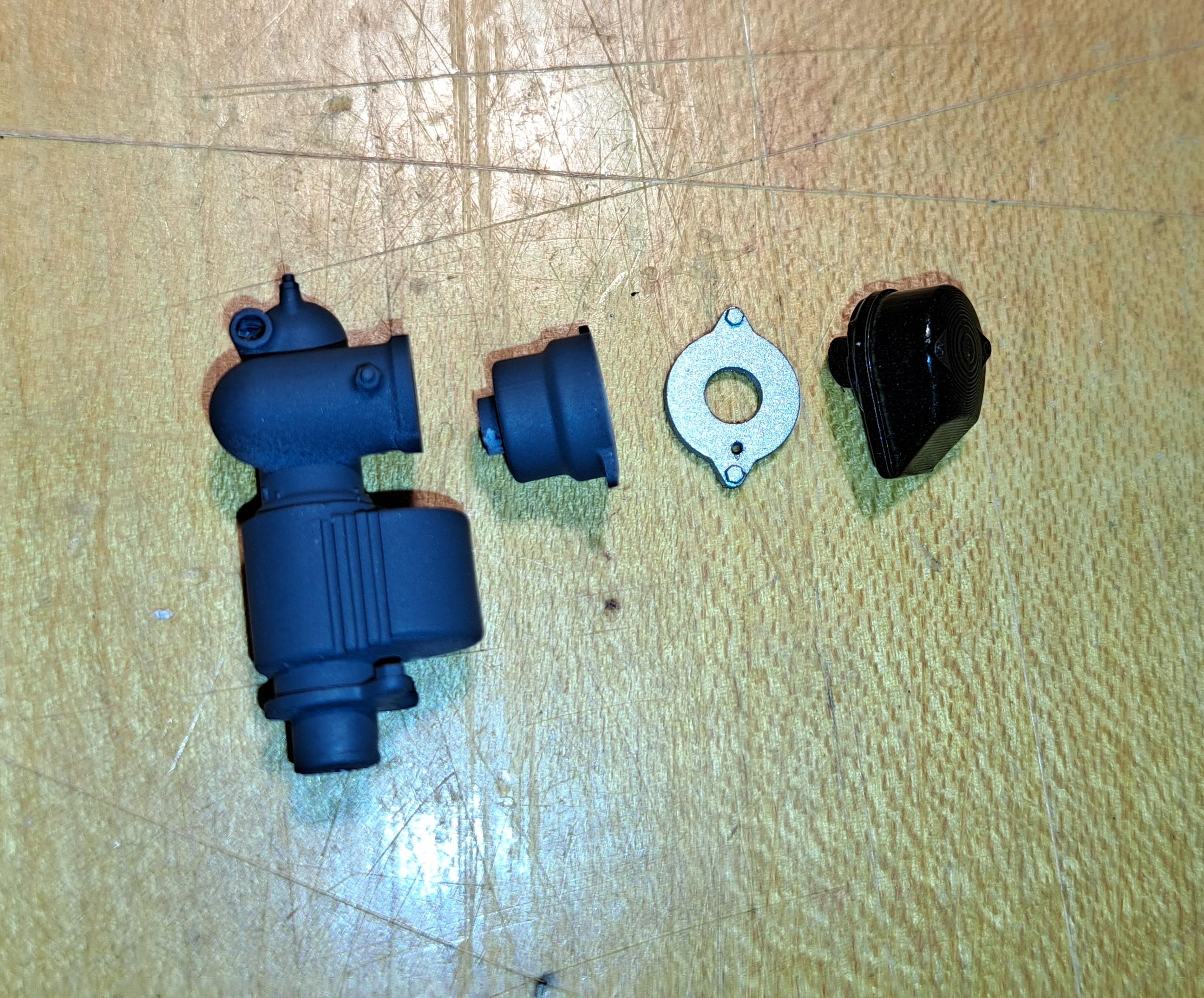
Distributer
Water pump

Fuel pump

A bunch of hydraulic fittings. I painted them aluminium then applied a yellow wash to get a cadmium plating affect

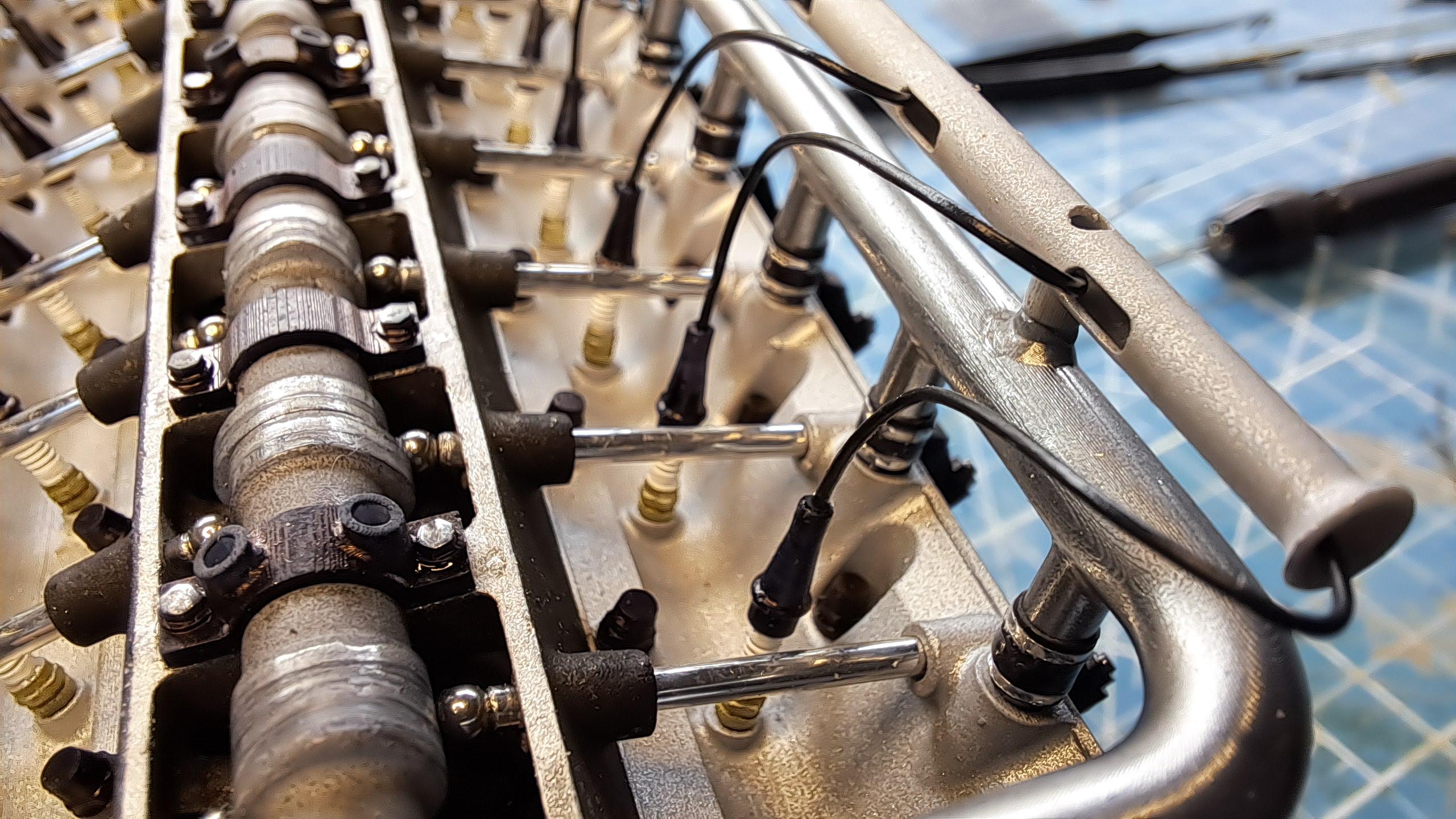
A spark plugs with rubber cap and wire (I'll do the cadmium effect too the lower portion of the plug)

I made a sanding jig to precisely sand the end of each crank shaft segment, there are 8 segments in all glued end to end so the lenght of each part needs to be a precise dimension in order to properly fit in the engine bloc.
The jig

The segment in the jig before sanding

And after sanding

Segments before and after

Here are some pictures.
Lower engine components

Exhaust (not painted)

Distributer

Water pump

Fuel pump

A bunch of hydraulic fittings. I painted them aluminium then applied a yellow wash to get a cadmium plating affect

A spark plugs with rubber cap and wire (I'll do the cadmium effect too the lower portion of the plug)

I made a sanding jig to precisely sand the end of each crank shaft segment, there are 8 segments in all glued end to end so the lenght of each part needs to be a precise dimension in order to properly fit in the engine bloc.
The jig

The segment in the jig before sanding

And after sanding

Segments before and after

Mondrasek, both the printer settings and environnement never change so that wasn't the problem. It was simply orientation and support placement. The first print was done with the crank axis vertical which requiered too many horizontal planes to be supported, it was the worst of the 4.
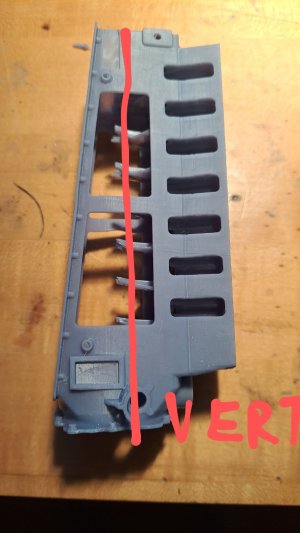
The second print was done with the crank axis horizontal which was much better but the sump flange and all crankshaft cradles failed.
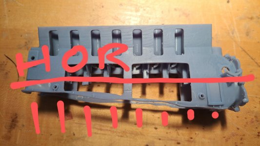
The third print was done with the sump flange horizontal but supported, the result was very good but the flange wasn't perfect
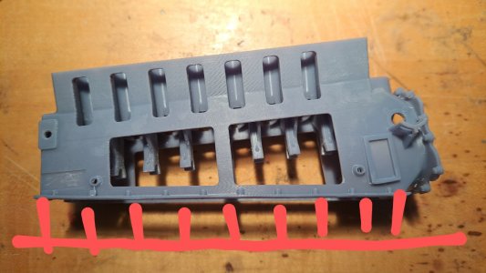
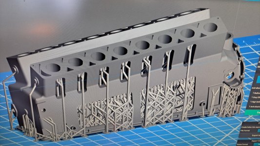
The 4th print was done with the sump flange directly on the plate. This requiers a bit of support gymnastic but the result was perfect. Live and learn!!
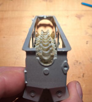
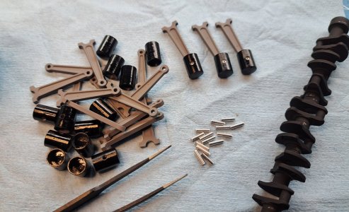
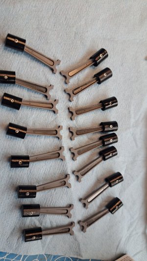
I assembled all 16 pistons and conrod.

The second print was done with the crank axis horizontal which was much better but the sump flange and all crankshaft cradles failed.

The third print was done with the sump flange horizontal but supported, the result was very good but the flange wasn't perfect

The 4th print was done with the sump flange directly on the plate. This requiers a bit of support gymnastic but the result was perfect. Live and learn!!


I assembled all 16 pistons and conrod.


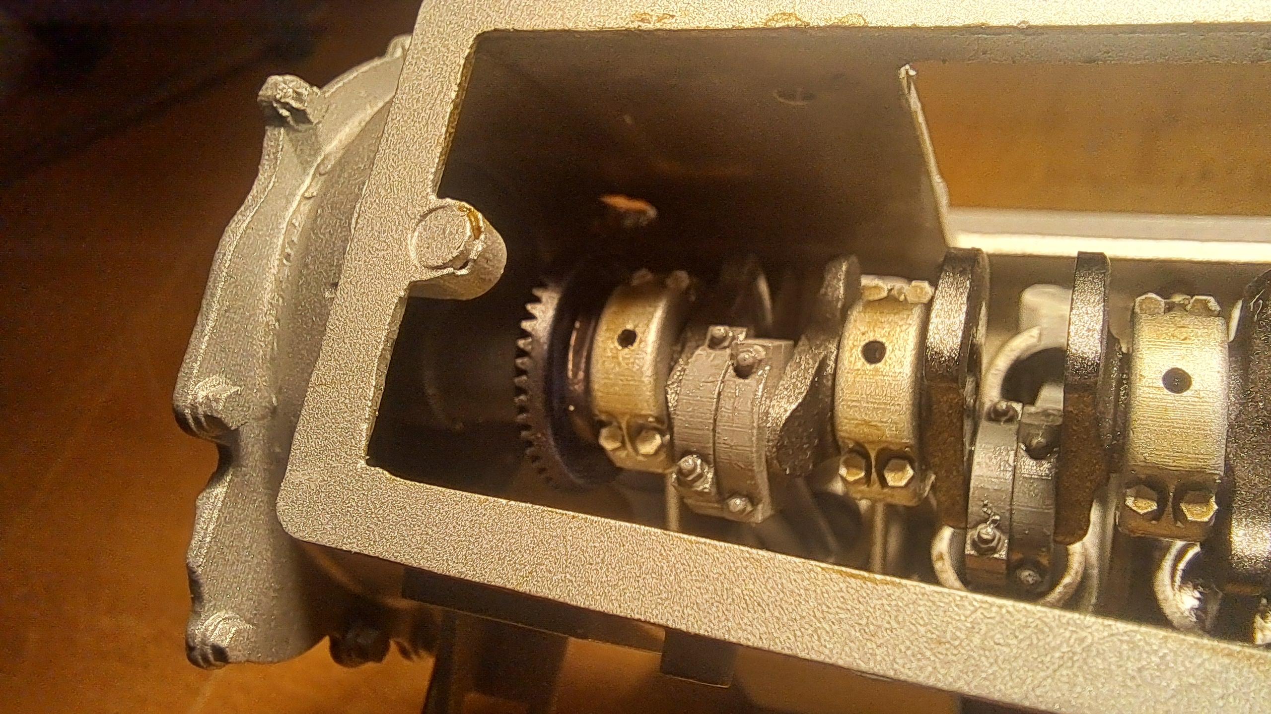
Ok so, I have many goals on this build. One was to have a working V16 engine and valve train that would drive the rear wheels. So far, as you're seen in my earlier post, the valve train is done and fonctionnal. Today, I made another step towards this goal. I now have a fully fonctionnal engine. All 16 pistons move from the crank shaft while driving the camshaft. I had my doughts but I pulled it off and it works very well, with very little torq needed to move averything. It wasn't easy to assemble but considering the precision needed but everything came together without a hitch. I more than pleased!!
Here are some pictures and videos, enjoy!




View attachment 20241221_192038.mp4
View attachment 20241221_193142.mp4
Here are some pictures and videos, enjoy!


View attachment 20241221_192038.mp4
View attachment 20241221_193142.mp4
Now that the engine is done, I started on the transmission. And, naturally, I had to complicate things. I thought it could be fun to have the choice of running the engine with or without the rear wheels turning. Do to that, I incorporated a sliding gear mecanism that will be actuated be the shifter. Here's a little video showing how the thing will work.
View attachment 20241224_203654.mp4
And a cross section of the engine with the transmission in place

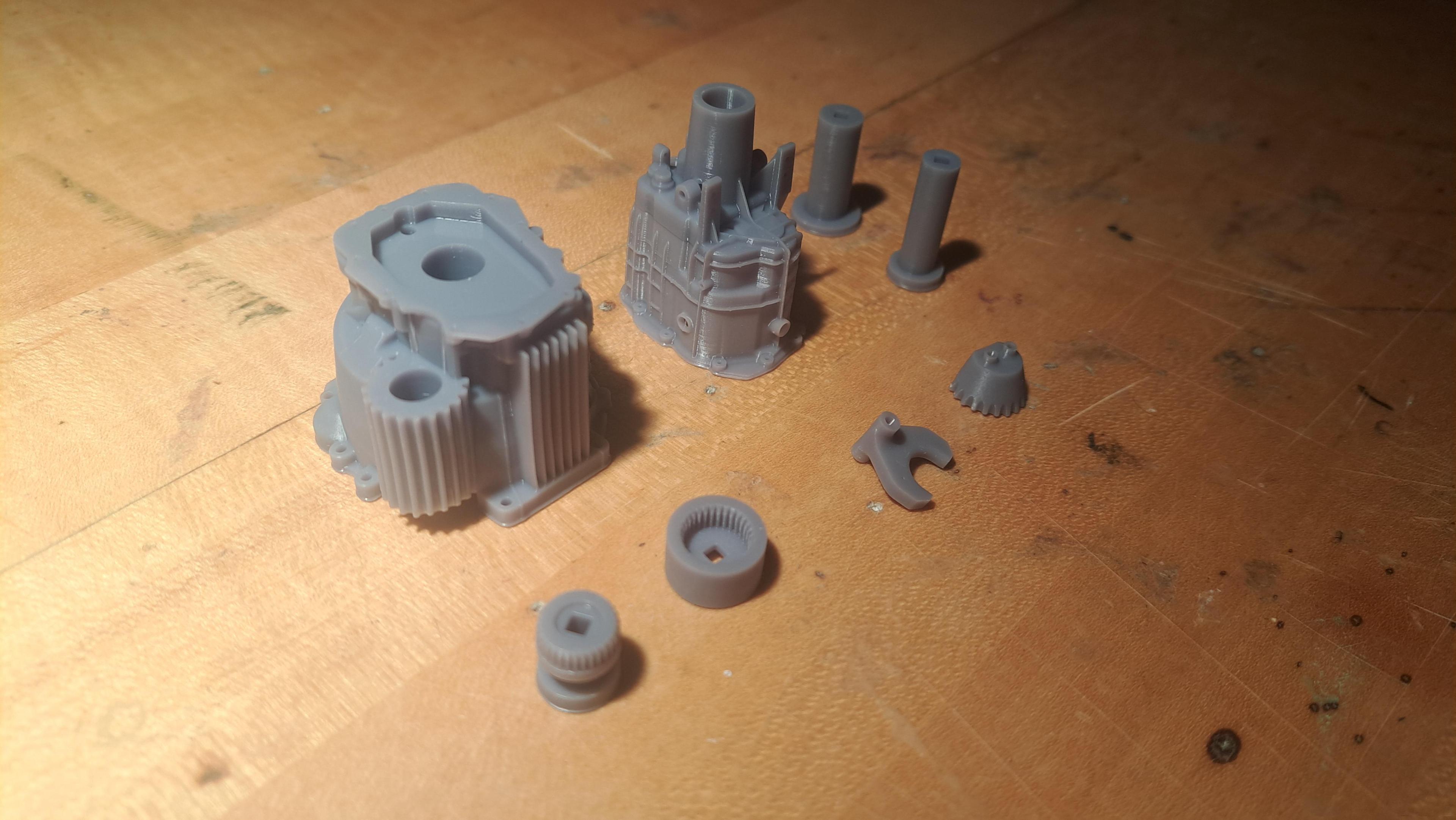
the printed parts

And mounted on the engine just to see what it will look like

That's it for now
Merry Christmas !!
View attachment 20241224_203654.mp4
And a cross section of the engine with the transmission in place

the printed parts


And mounted on the engine just to see what it will look like

That's it for now
Merry Christmas !!
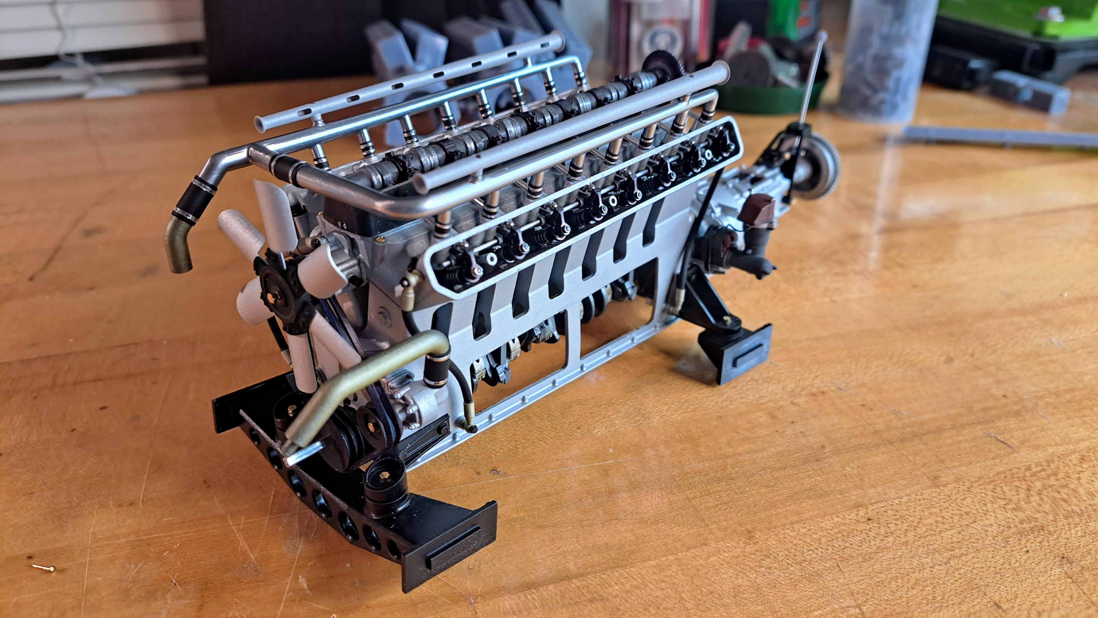
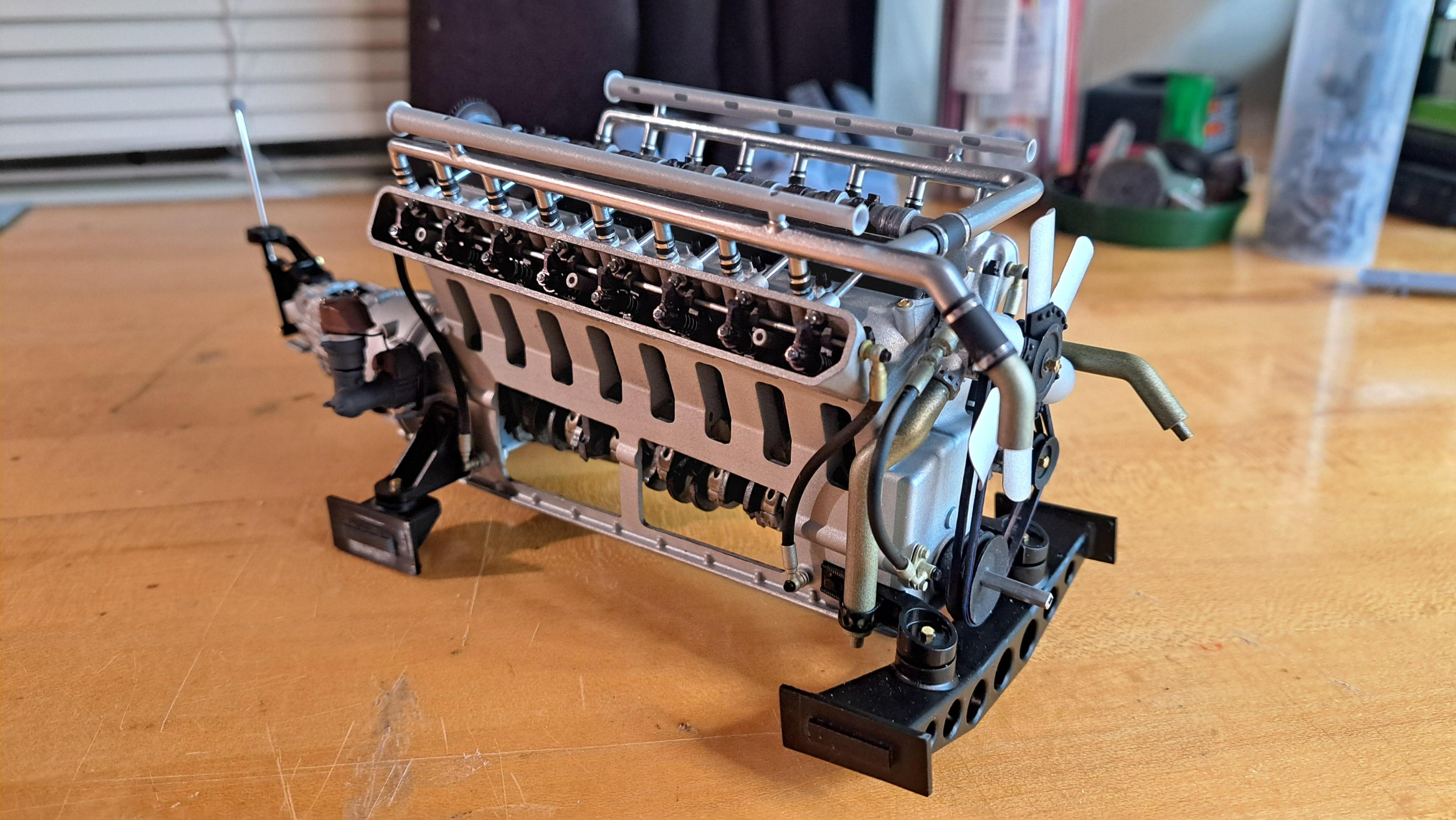
Well, the Hydra Coupe 16 cylinder engine is done and it's a beast! You might think it's out of scale for a 1/12 model but it's not. Everything is to scale. Unlike some other large scale engine out there, If you were to blow it up 12 times, this one would actually look like a very huge V16 engine. Althought I will admit I might have spaced the cylinder bores a bit more than necessary to fill the engine bay. I still need to put in the plug wires and fine tune the fit of the clutch but aside from that, it's done. The transmission is mounted and the drive/no drive mecanism works well. I've ordered a few micro gearmotors (2 different ratios). The gearmotor will be hidden inside the starter motor housing and will drive the ring gear. In the meantime, I can rotate the engine using the transmission output shaft.
Here are some pictures of the transmission assembly, followed by pictures of the completed engine and a small video.
All transmission parts ready for assembly


The completed engine
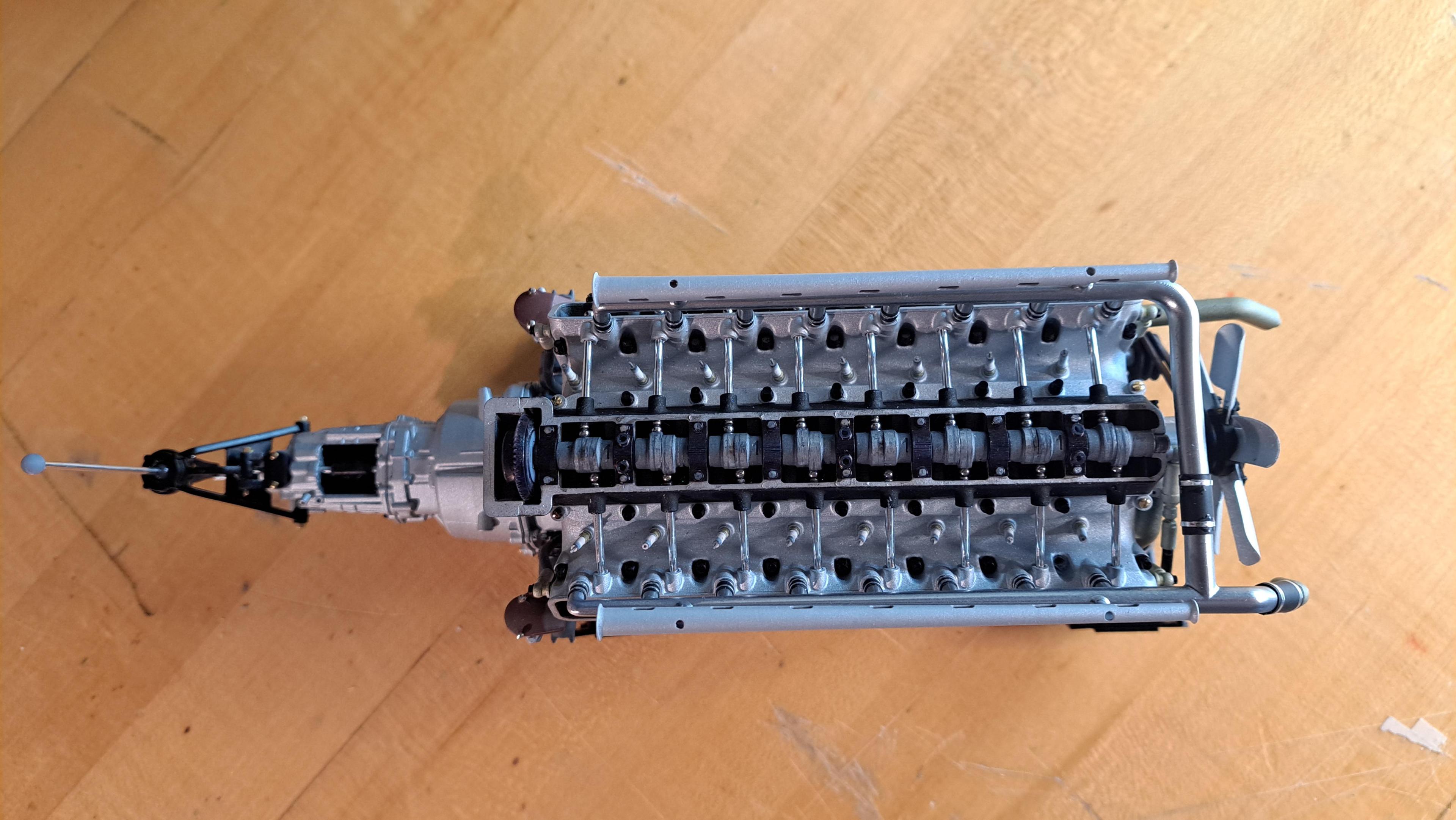



And some details

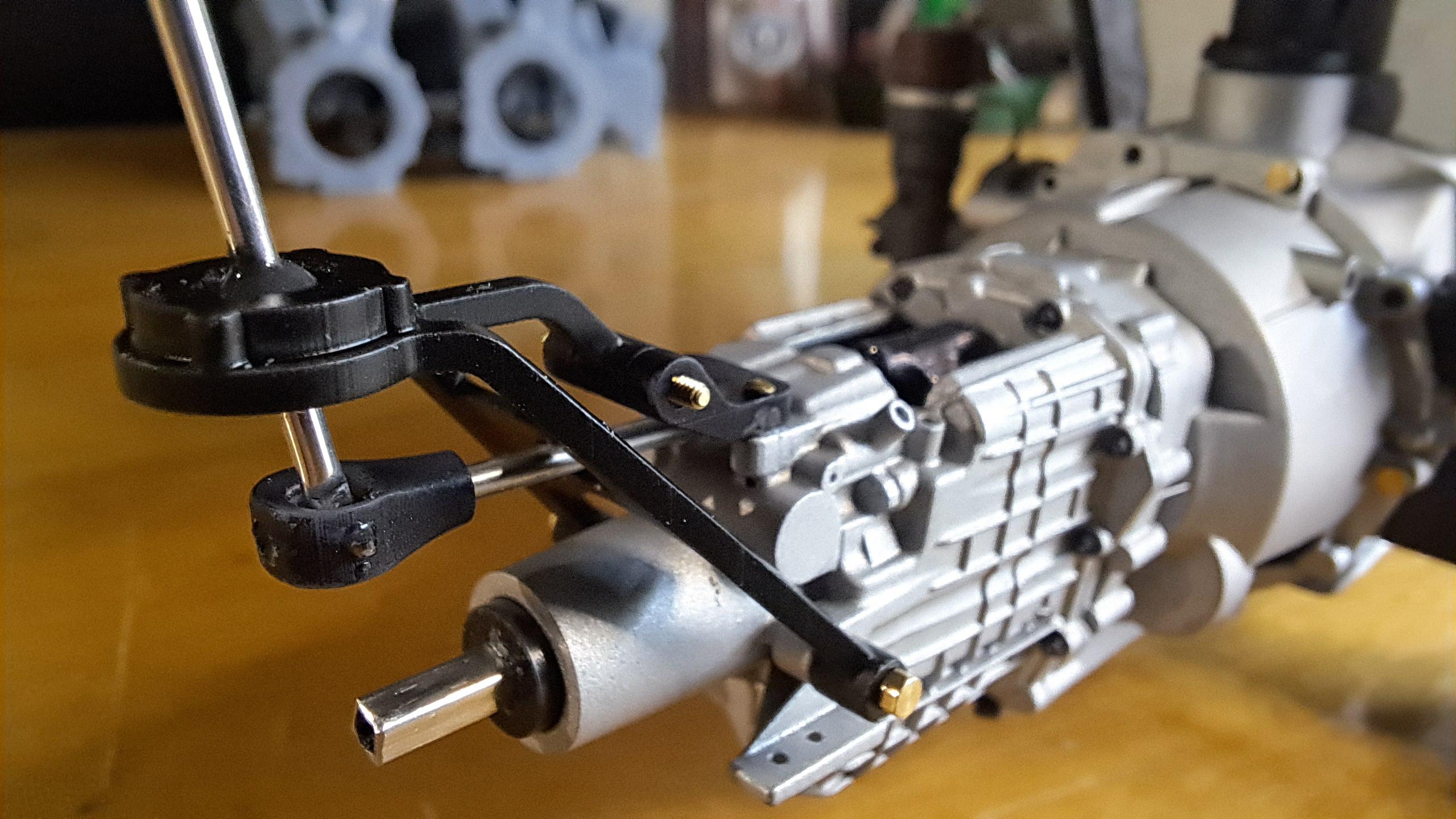
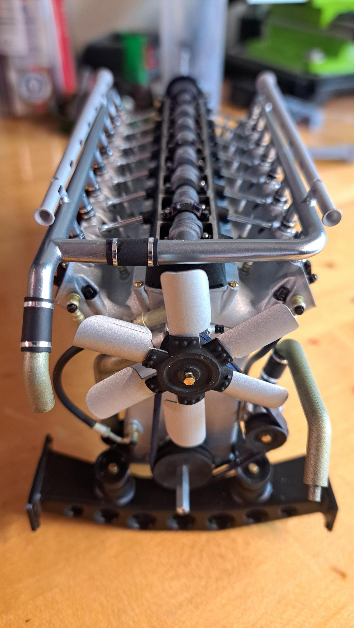
Snd a small video showing the drive mecanism being engaged
View attachment 20241229_205449.mp4
Next up, the frame, suspension components and front and rear ends.
Here are some pictures of the transmission assembly, followed by pictures of the completed engine and a small video.
All transmission parts ready for assembly


The completed engine


And some details


Snd a small video showing the drive mecanism being engaged
View attachment 20241229_205449.mp4
Next up, the frame, suspension components and front and rear ends.
It’s going to be a very impressive engine, François.Well, the Hydra Coupe 16 cylinder engine is done and it's a beast! You might think it's out of scale for a 1/12 model but it's not. Everything is to scale. Unlike some other large scale engine out there, If you were to blow it up 12 times, this one would actually look like a very huge V16 engine. Althought I will admit I might have spaced the cylinder bores a bit more than necessary to fill the engine bay. I still need to put in the plug wires and fine tune the fit of the clutch but aside from that, it's done. The transmission is mounted and the drive/no drive mecanism works well. I've ordered a few micro gearmotors (2 different ratios). The gearmotor will be hidden inside the starter motor housing and will drive the ring gear. In the meantime, I can rotate the engine using the transmission output shaft.
Here are some pictures of the transmission assembly, followed by pictures of the completed engine and a small video.
All transmission parts ready for assembly

The completed engine
And some details


Snd a small video showing the drive mecanism being engaged
View attachment 492400
Next up, the frame, suspension components and front and rear ends.
Regards, Peter


