Yup, that's exactly what it is. A totally useless gadget. But it will be cool to see it turn with the engine. Providing the micro gear motor I'm planning to use is strong enough to rotate 16 pistons plus the drive train plus some other gears. I'm starting to have some doughts !!
-

Win a Free Custom Engraved Brass Coin!!!
As a way to introduce our brass coins to the community, we will raffle off a free coin during the month of August. Follow link ABOVE for instructions for entering.
-

PRE-ORDER SHIPS IN SCALE TODAY!
The beloved Ships in Scale Magazine is back and charting a new course for 2026!
Discover new skills, new techniques, and new inspirations in every issue.
NOTE THAT OUR FIRST ISSUE WILL BE JAN/FEB 2026
- Home
- Forums
- Ships of Scale Build Logs
- Super Detailing Static Models / Other Genres
- Historical Trailways, Guns, Aircraft, and Cars
You are using an out of date browser. It may not display this or other websites correctly.
You should upgrade or use an alternative browser.
You should upgrade or use an alternative browser.
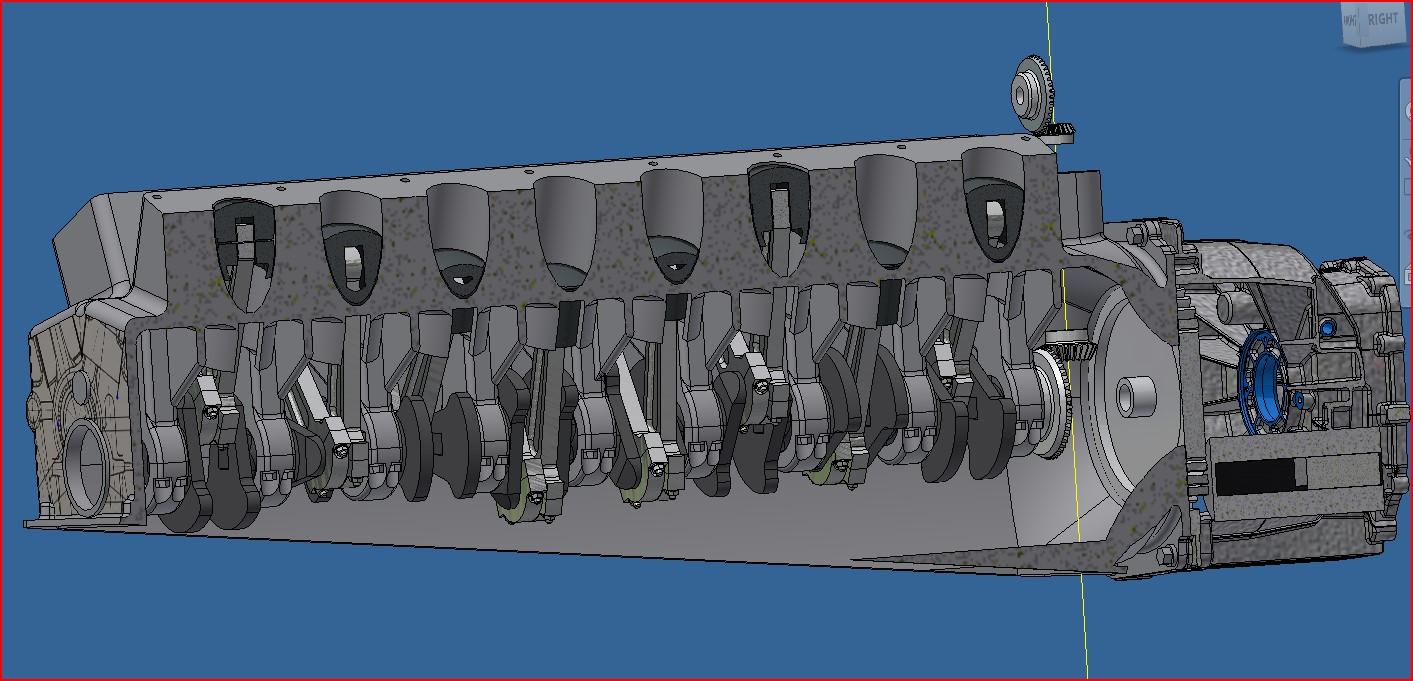
Did a bit more work on the V16 engine. That is a lot of pistons! It will be fun to watch if ever I'm able to pull this off and have a running engine. Like I said before, there's very little info on the Auto Union V16 so to get a somewhat realistic firing sequence, I found a little youtube that explains the sequence for the new Bugatti V16.
View attachment 20241004_220959.mp4
View attachment 20241004_221107.mp4

View attachment 20241004_220959.mp4
View attachment 20241004_221107.mp4
Francois - did you look at the 1930 Cadillac V16 as well? There seems to be a fair amount of information available for that 'monster'. I know that you will do a great job on the one you are making now but this may be worth at least getting some ideas about how these work:https://www.motortrend.com/vehicle-genres/cadillac-v-16-engine-history-photos-specifications/ and https://en.wikipedia.org/wiki/Cadillac_V-16
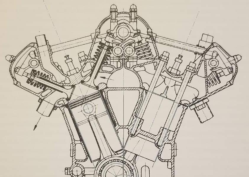
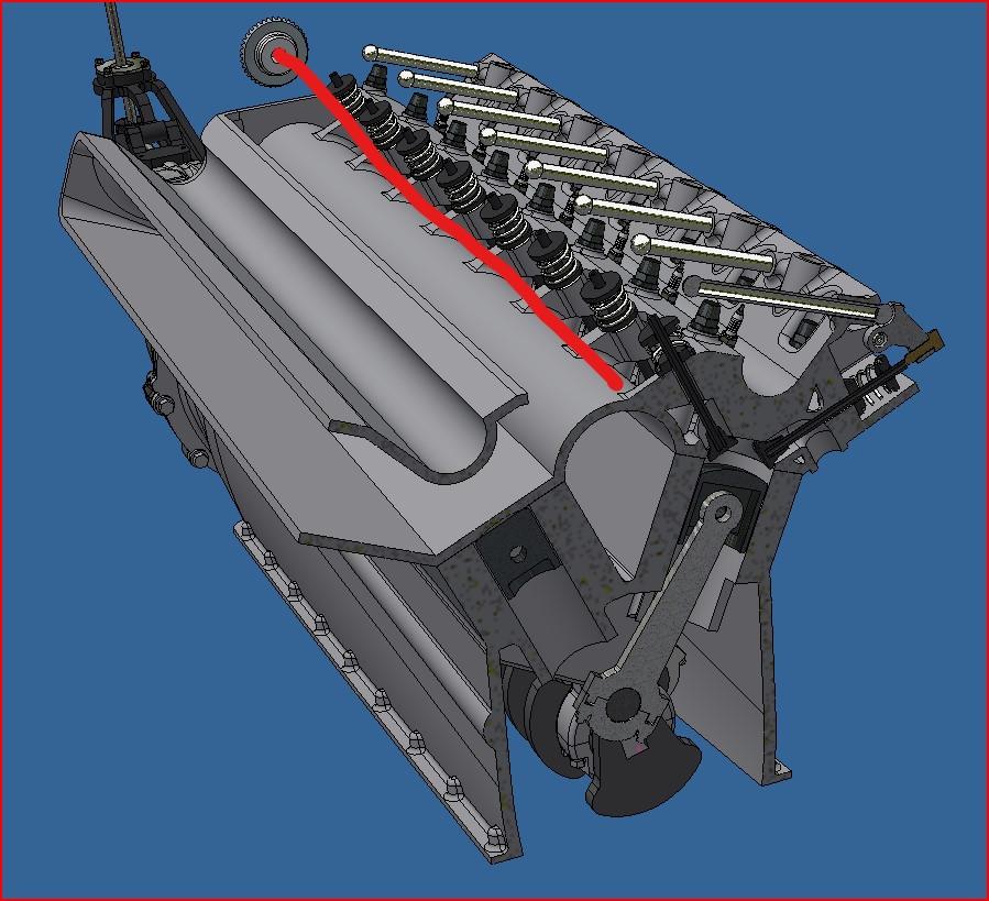
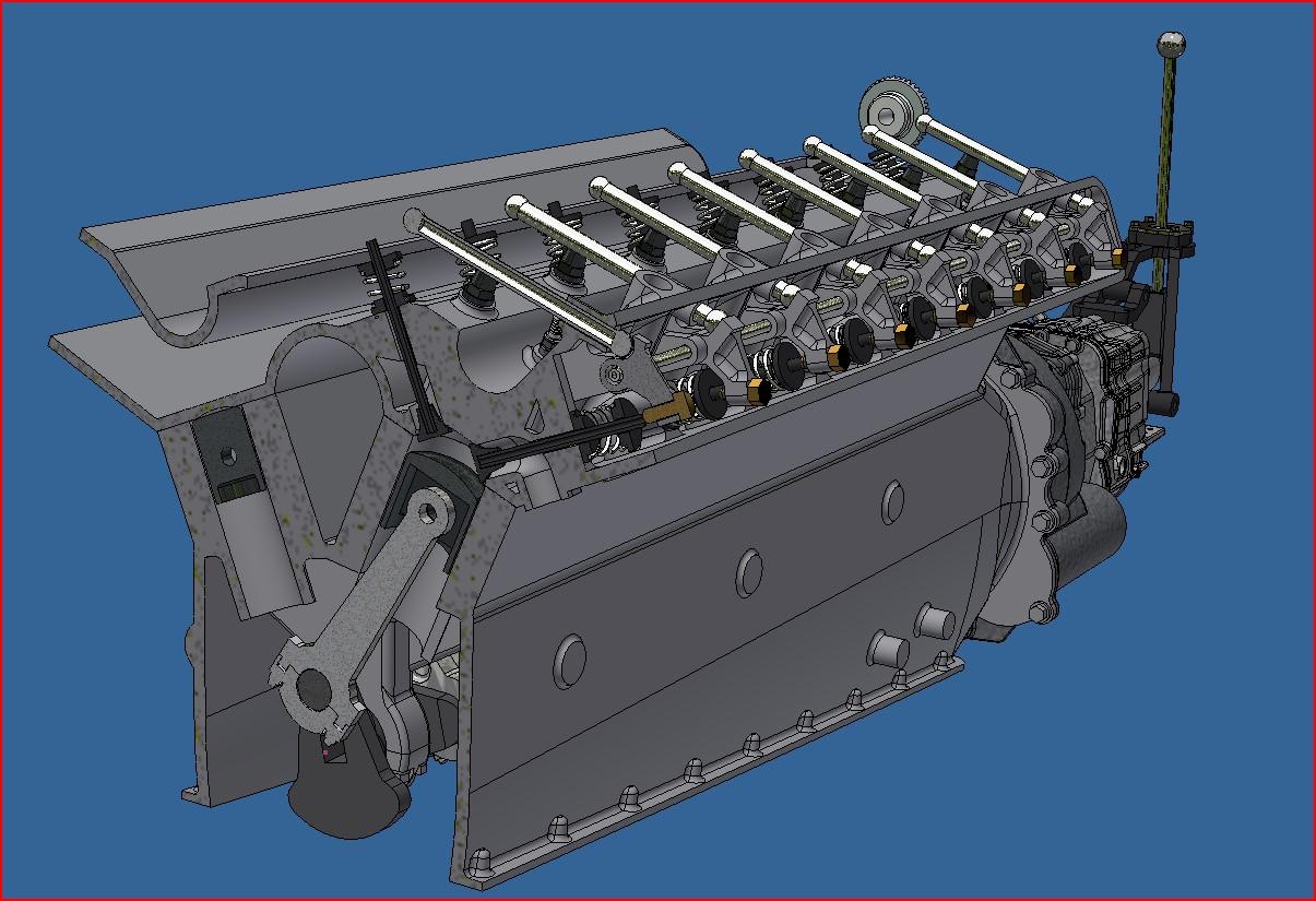
Made some progress on the valve train today. It's a fairly complicated system. The cam shaft is located on top in the center, between the 2 heads. Each head has a set of 8 rockers actuating the outside valves (exhaust). These rockers are actuated via 8 horizontal rods( or close to horizontal) going towards the cam shaft, not too sure exactly how these rods are moved but I suspect that they are directly in contact with the cam shaft. And positionned just beneat the cam shaft there will be another 16 rockers, 8 to activate the the left side intake valves and 8 for the right side valves. My goal is to try and have working valves but really not sure I'll be able to. I will print every part so at worst it will be static.
Here is a cross cut of my ref engine where you can see the valves, rockers and horizontal rods.
And here's where I'm at. The red line would be the cam shaft.
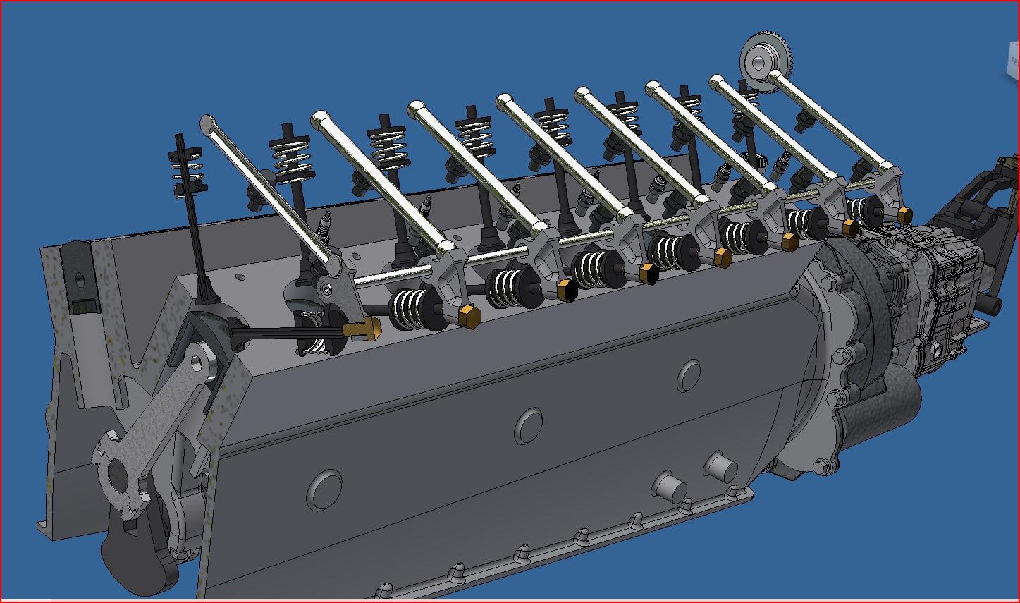
Here is a cross cut of my ref engine where you can see the valves, rockers and horizontal rods.

And here's where I'm at. The red line would be the cam shaft.


Ok, so the valve train is all done and it's a thing of beauty! And it works! Well at least in Inventor it works... This is one complicated system. It's one thing to reproduce it with todays design tools but imagine doing this back in the 30's. These guys were good. I did print a few test parts and I do have one working valve/rocker. Up next is the camshaft drive which I will base the design on the Bentley's. Here are some pictures, screen shots and videos of the finish valve system.
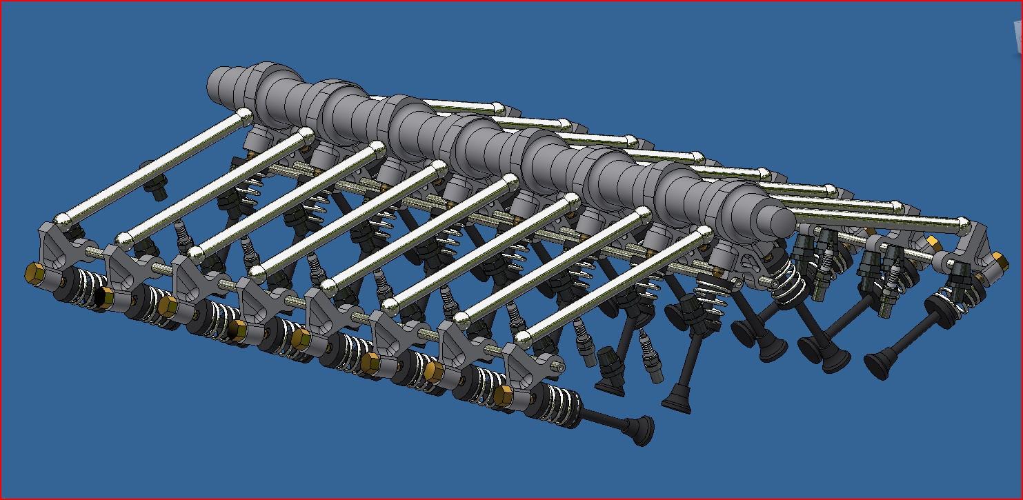
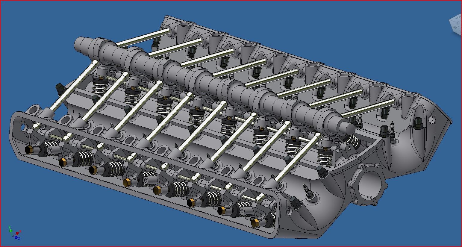
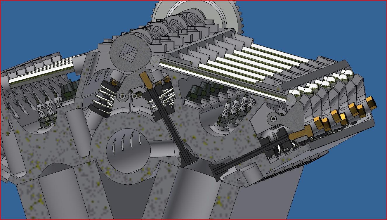
test valve and rocker arm
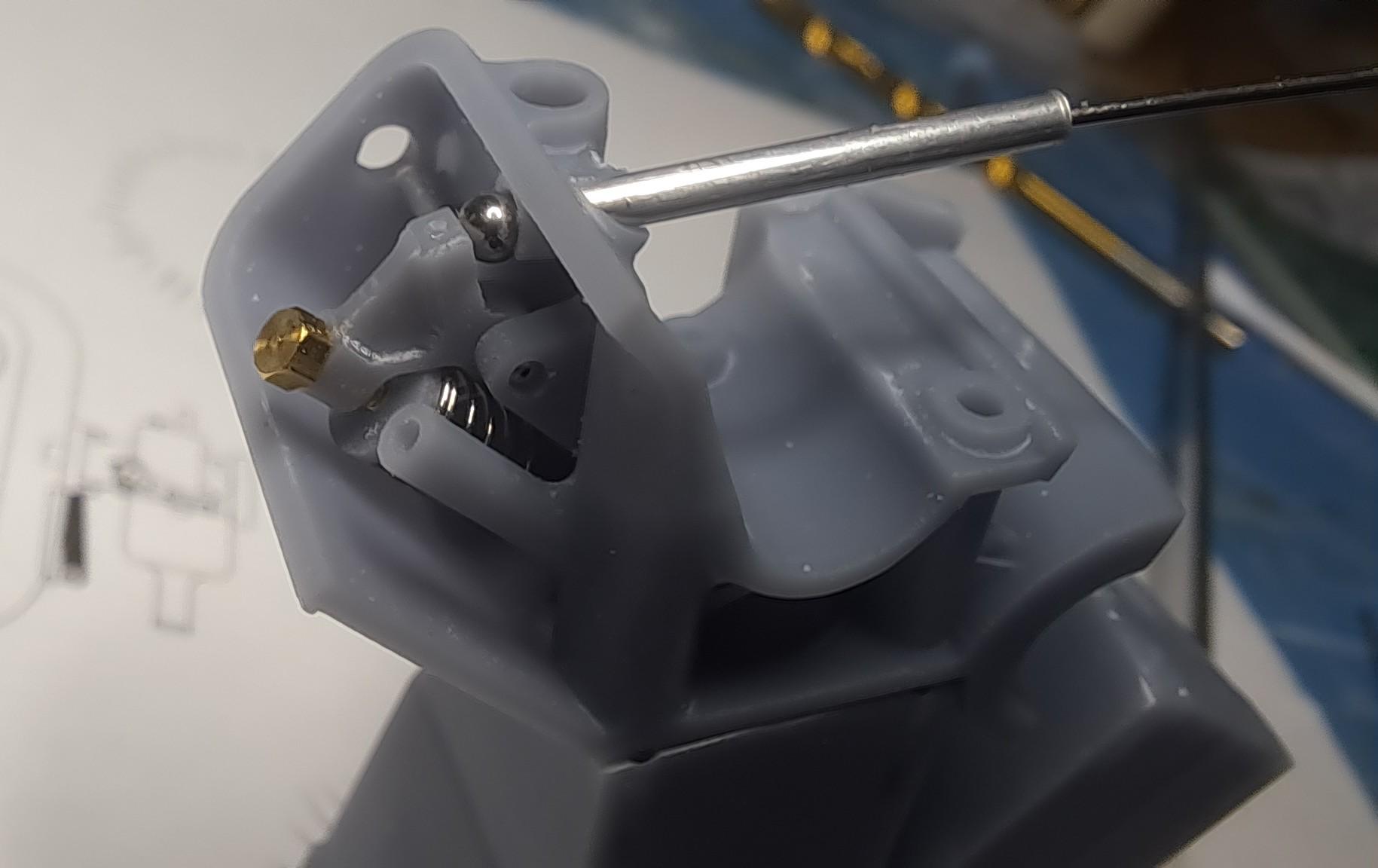
Test piston and crank
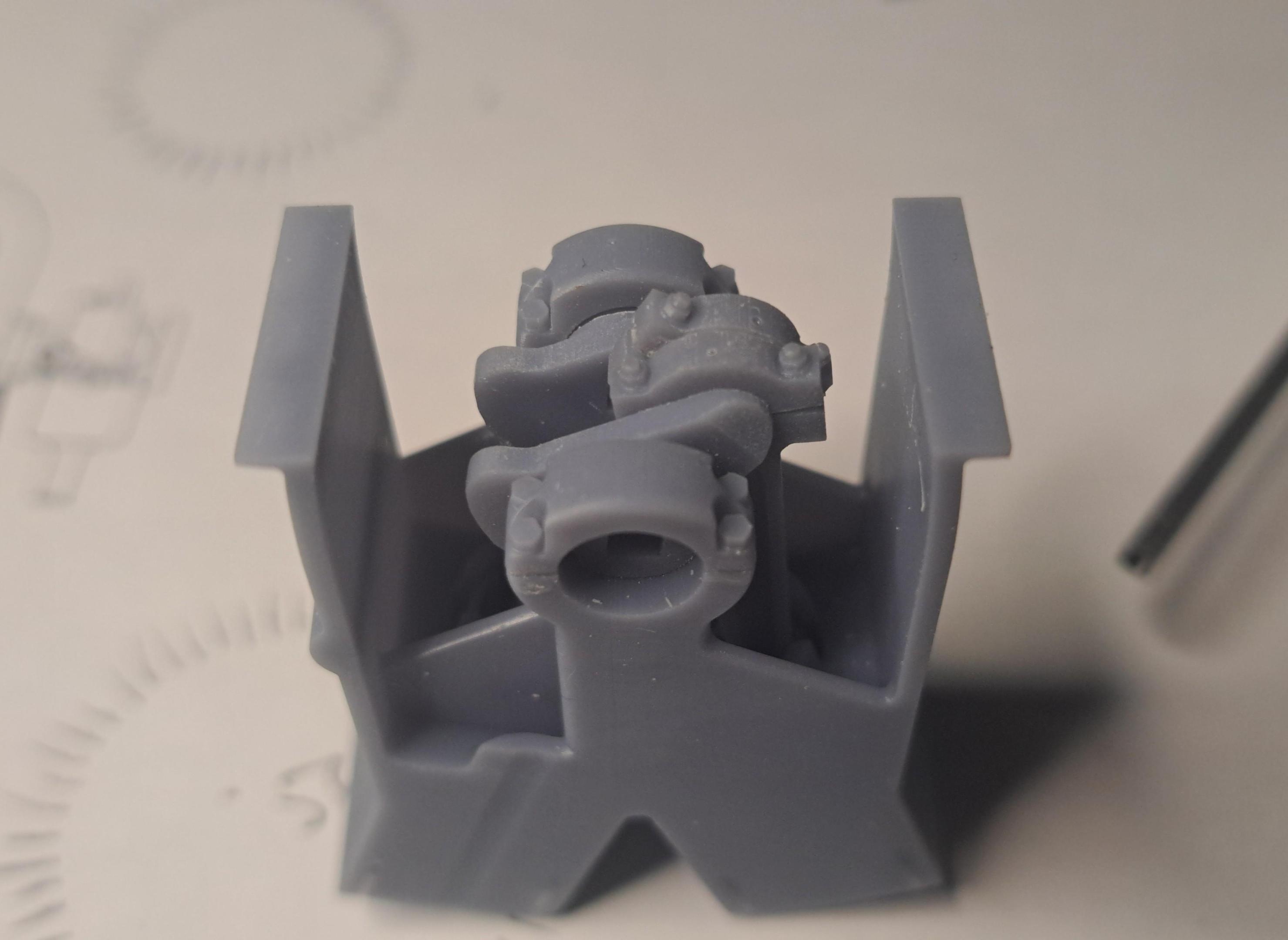
the full valve train in motion
View attachment 20241015_201447.mp4
And test valve and rocker arm in motion
View attachment 20241015_201844.mp4


test valve and rocker arm

Test piston and crank

the full valve train in motion
View attachment 20241015_201447.mp4
And test valve and rocker arm in motion
View attachment 20241015_201844.mp4
I made another test print to see if the valves could be actuated via the camshaft. It appears that they can but I only put in 4 valves. I'm a long way from having 32 working valves. The test did show me where I need to make design modifications. All in all, I'm happy with the result and it was really fun to do but still not sure if it will go into the final engine.
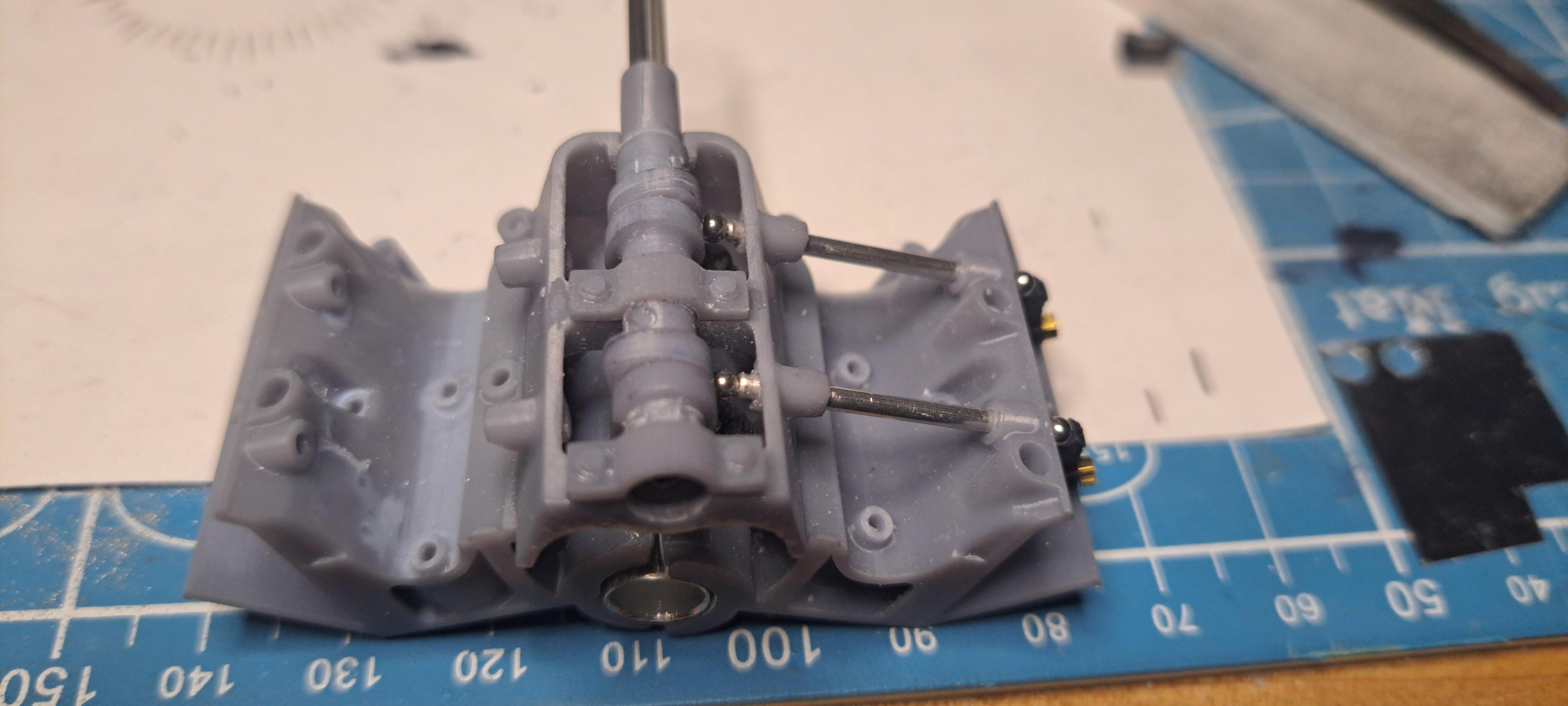
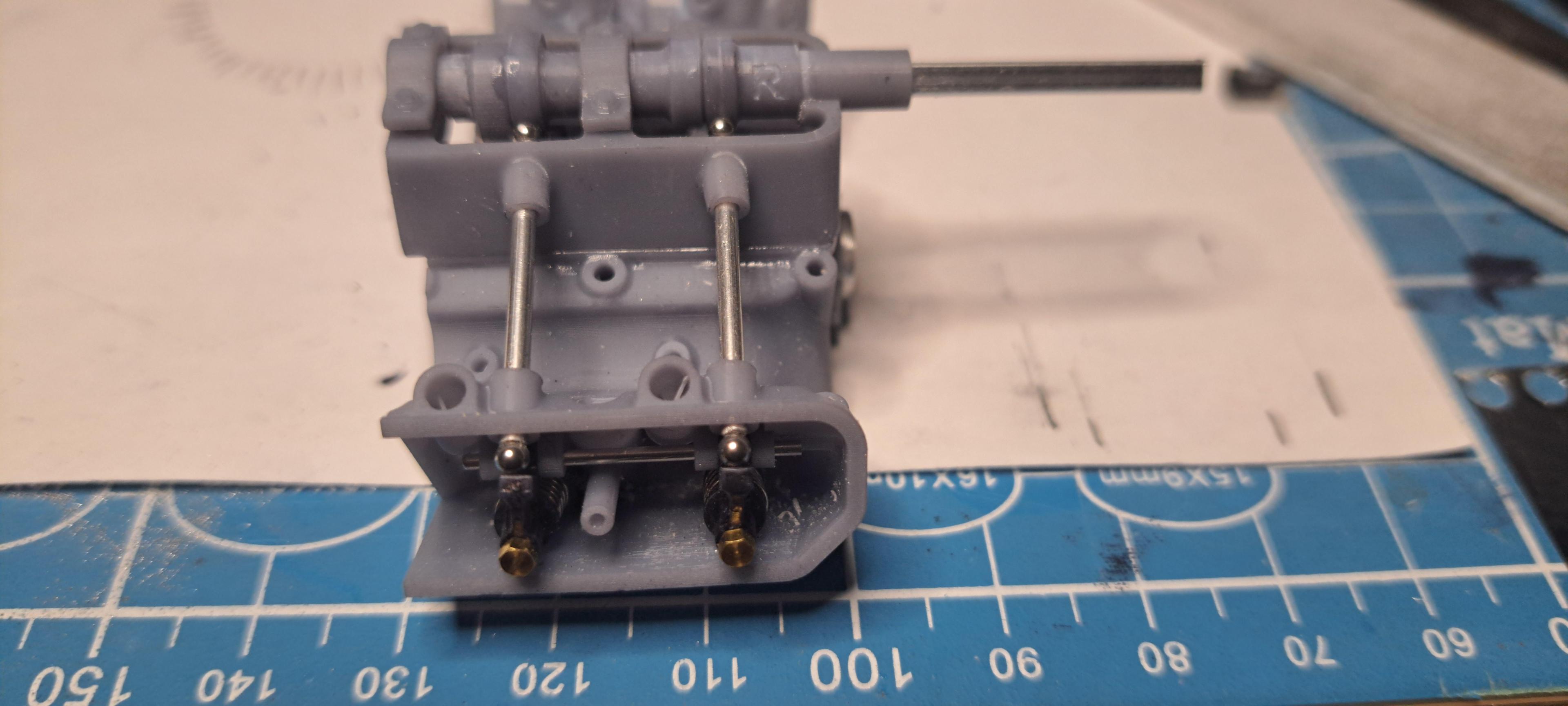
View attachment 20241016_202242.mp4
View attachment 20241016_202303.mp4


View attachment 20241016_202242.mp4
View attachment 20241016_202303.mp4
After a month off, I'm back on the hydra coupe.
Althougt the design is not 100% done, I started printing some parts. Back on october, I printed a test engine head with a few valve and rockers. I learned a lot from it and made a few design changes. So I reprinted the full head and after a first fail, I think I have something that should be good. I'm still aiming on having a working valve train and this adds to the precision and level of detail I need to but in. I'm always impressed by what comes out of the printer. This is really a case of 'garbage in, garbage out' so I must be feeding the printer good stuff because the results are very nice!!
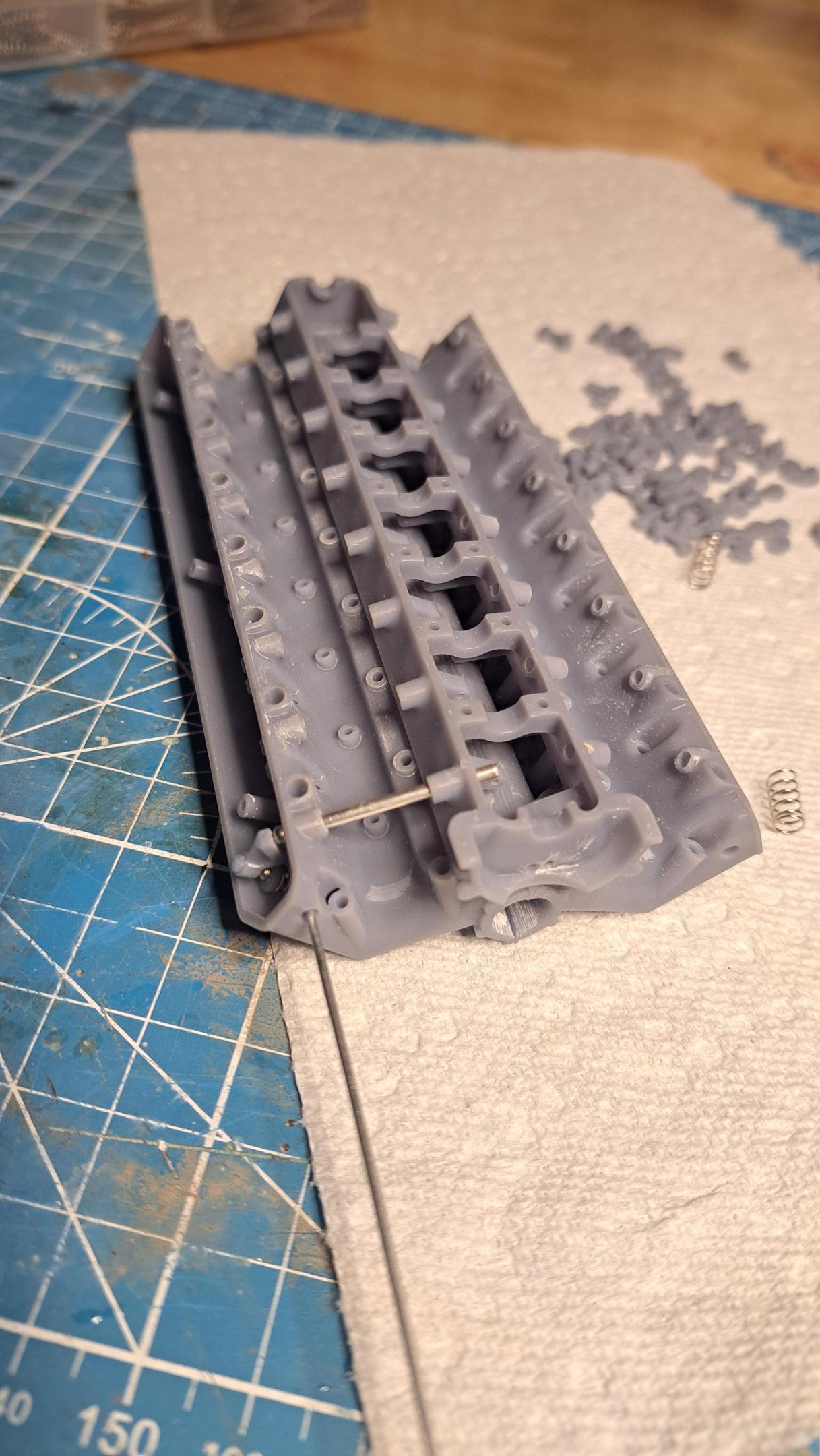

Althougt the design is not 100% done, I started printing some parts. Back on october, I printed a test engine head with a few valve and rockers. I learned a lot from it and made a few design changes. So I reprinted the full head and after a first fail, I think I have something that should be good. I'm still aiming on having a working valve train and this adds to the precision and level of detail I need to but in. I'm always impressed by what comes out of the printer. This is really a case of 'garbage in, garbage out' so I must be feeding the printer good stuff because the results are very nice!!


Thats incredible detail François. I know something of what it takes to draw that up in 3D.
More work done on the engine head, I printed a boat load of small parts. I actually have 2 head castings printed, one is perfect and one has a few flaws. I'm using the flawed one as a test bench to make sure my fits are good and that what needs to move move's correctly. So I fitted a partial camshaft along with the bevel gear setup and one rocker/valve and hooked it up to my dremel and let her rip. It ran like clockwork. Here's a little video showing the rocker mouvement. I had to slow the video by 50% in order to see it move.
View attachment 20241119_133449~3.mp4
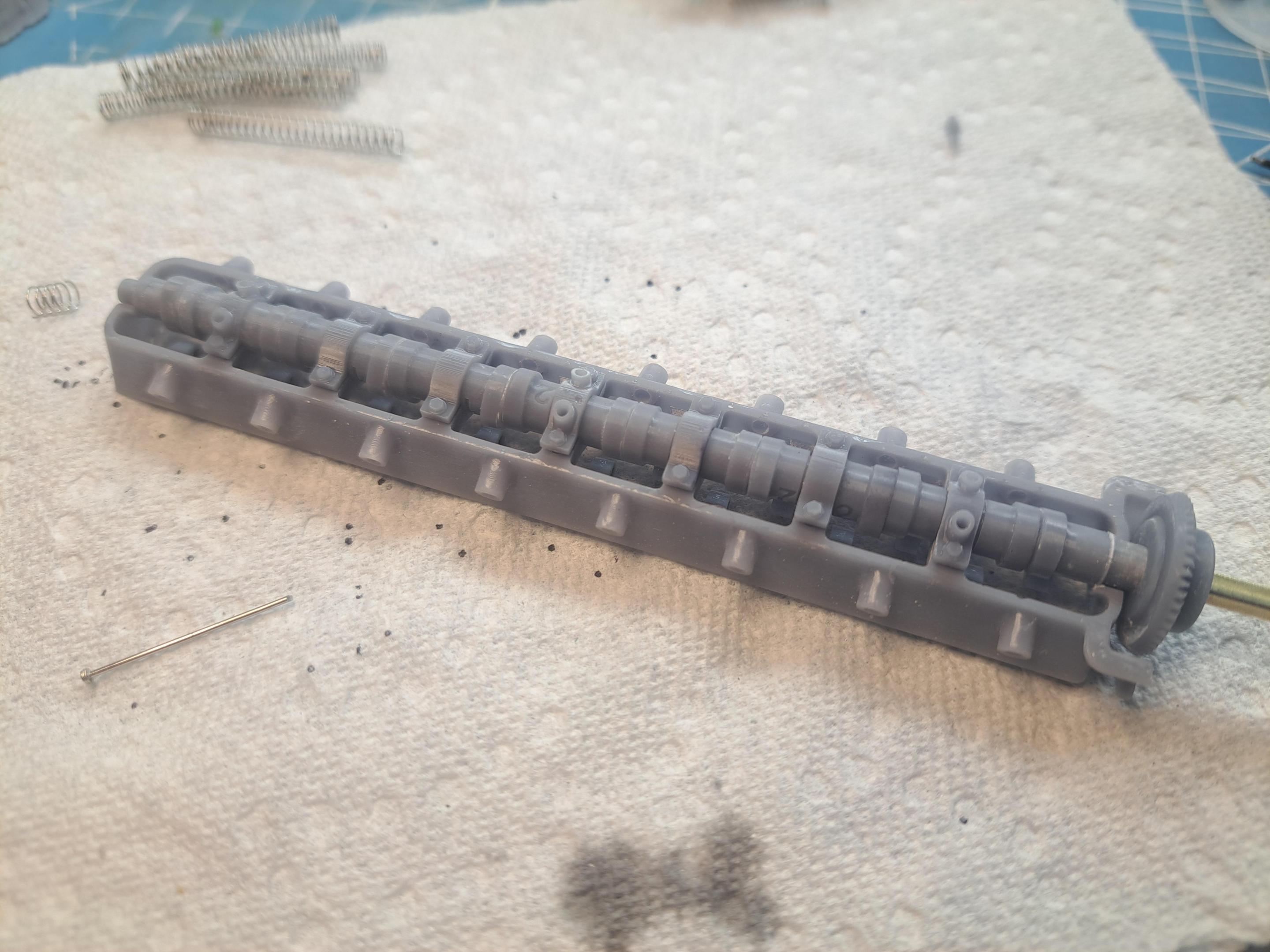
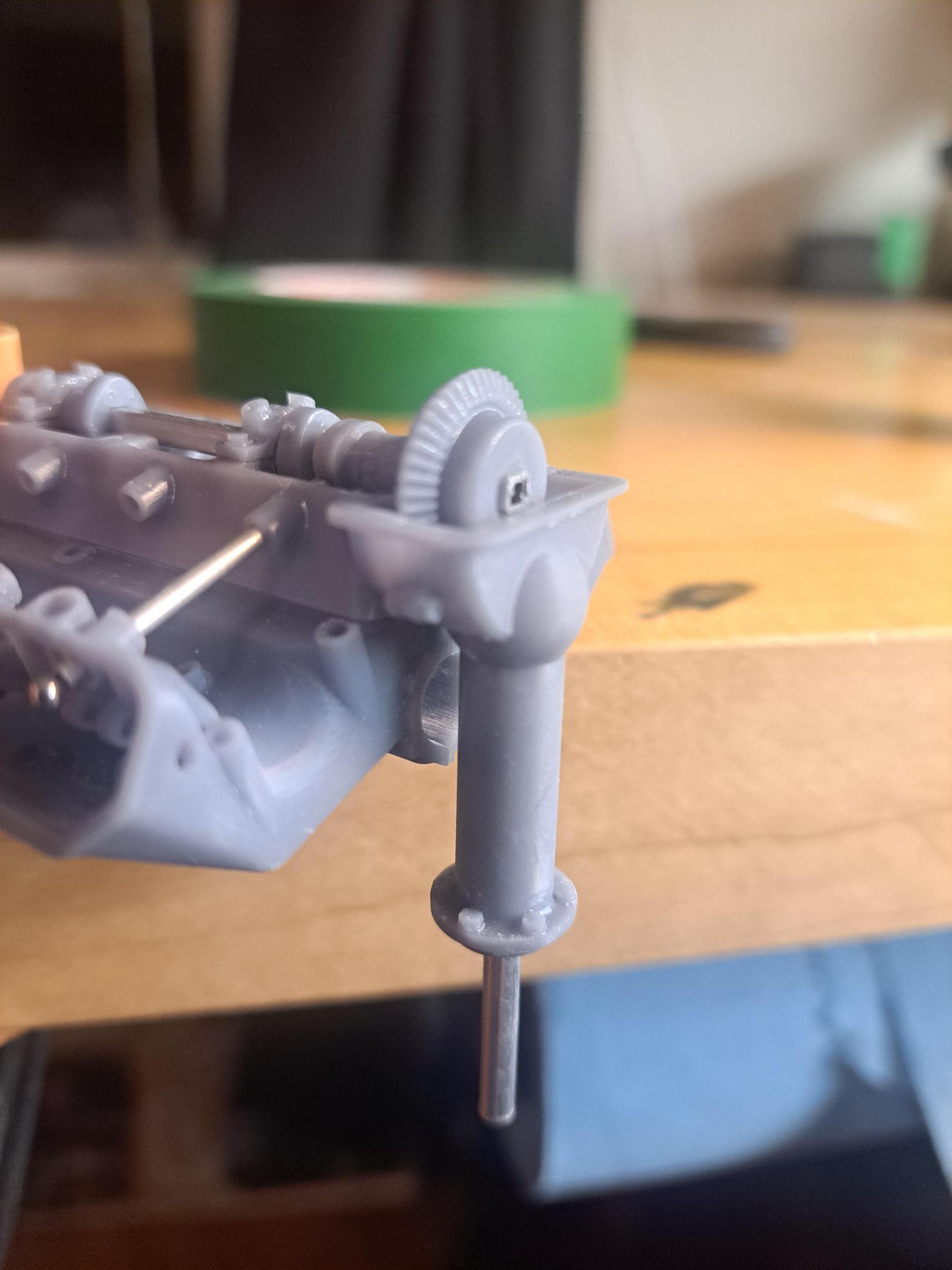
And here are some pictures of the different parts printed
Valves
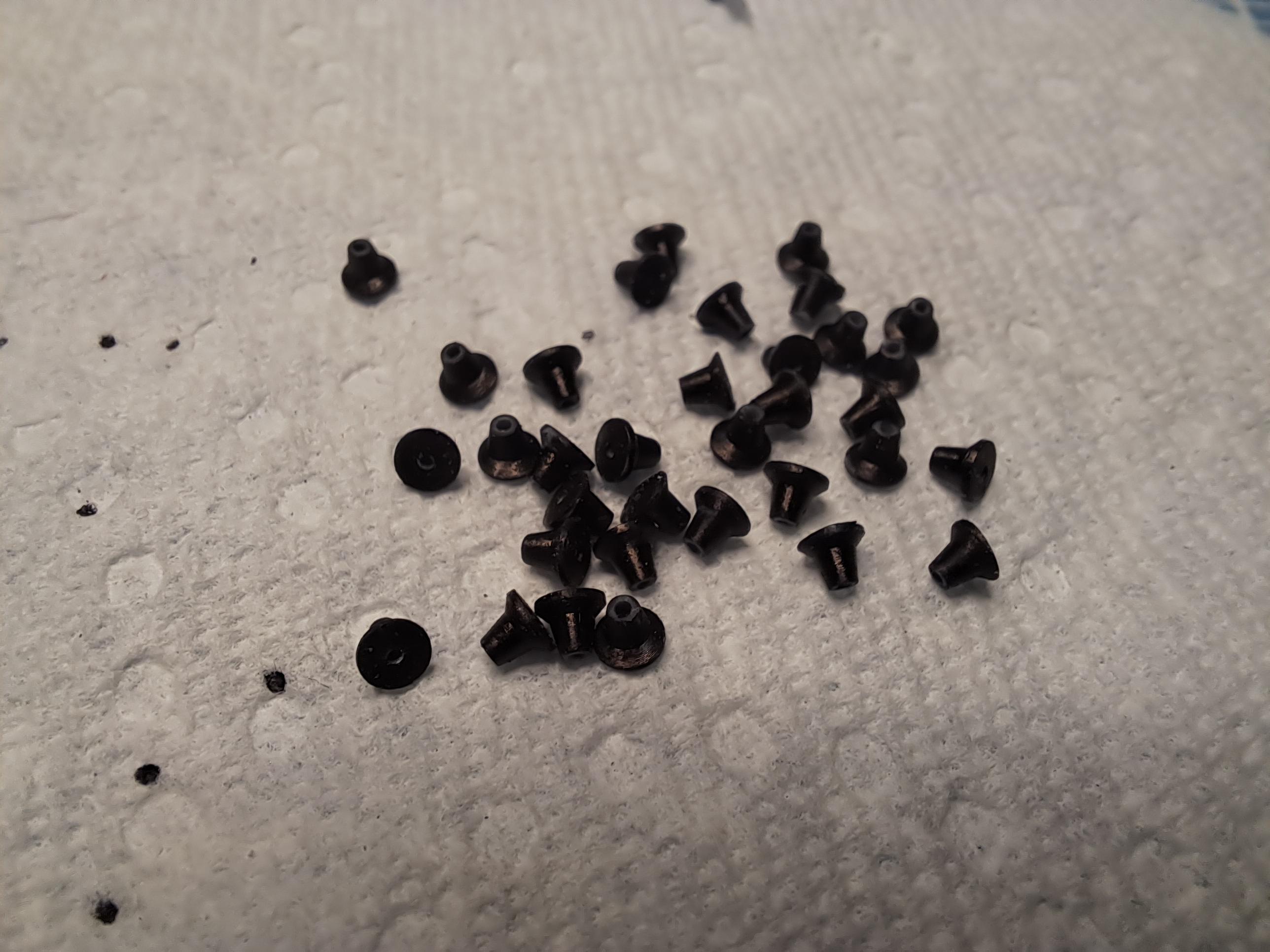
Rockers

The cam shaft (not final yet)
And the bevel gear housing (I borrowed the turret idea from the bentley blower)
View attachment 20241119_133449~3.mp4
And here are some pictures of the different parts printed
Valves

Rockers

The cam shaft (not final yet)

And the bevel gear housing (I borrowed the turret idea from the bentley blower)

Last edited:
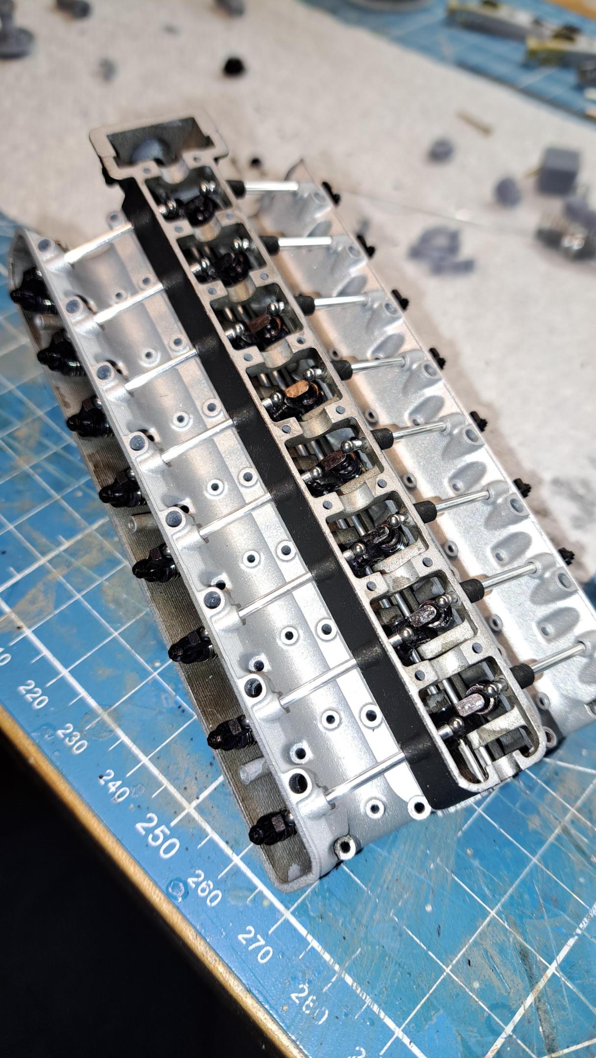
I made good progress on the head today. All 32 valves are made and in place, painted the head casting flat aluminium and added some engine grime in the concaved areas, assembled and painted the camshaft complete with simulated grounded lobe surfaces (I used a chrome pen for this) and installed the exhaust valve rockers. The black finish on the rockers is done with a permanent marker, easy to apply, close to zero thickness and dries very fast.
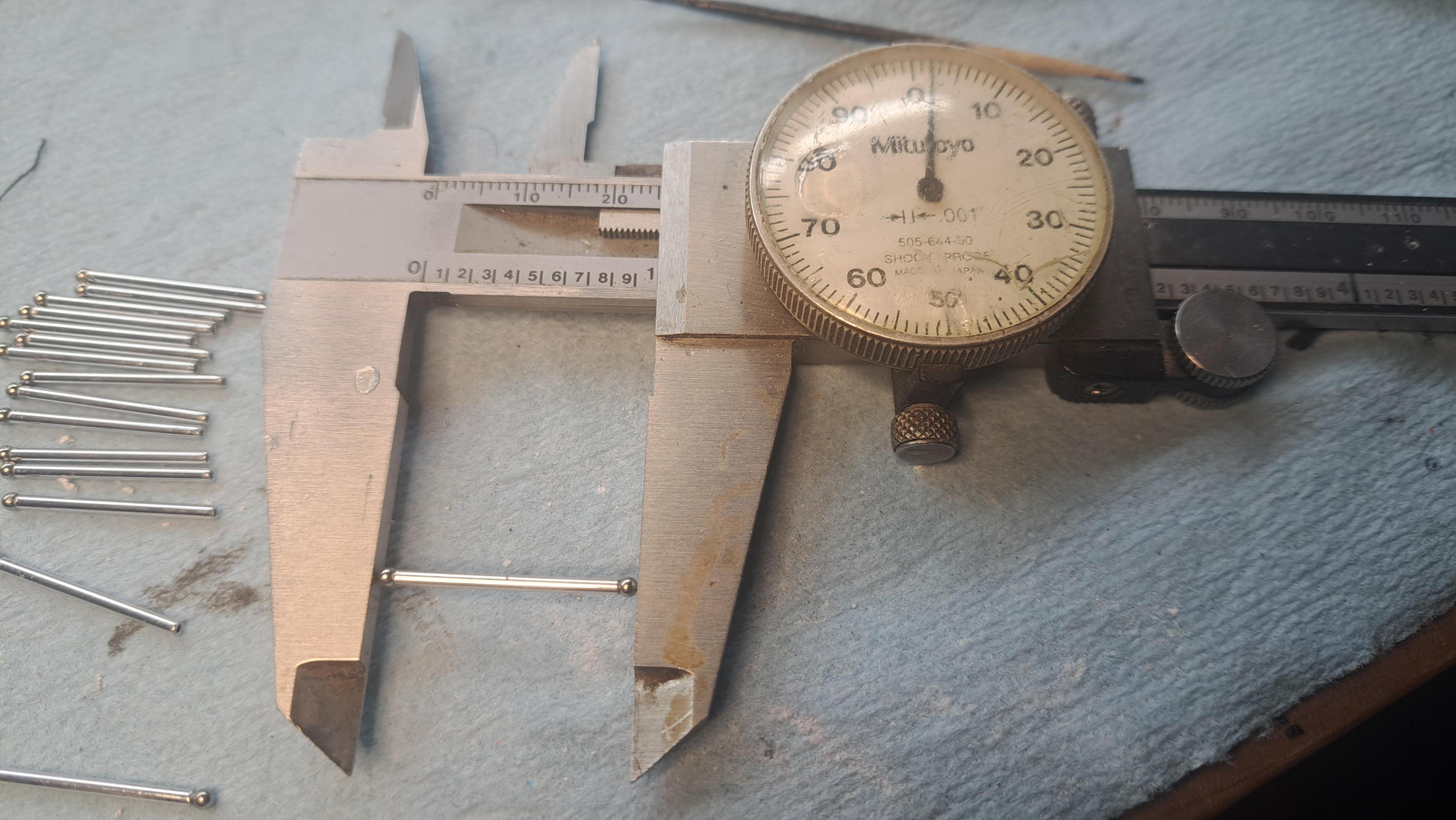
I also made 16 aluminium push rods with spherical heads at both ends. These rods need to be exactly 1.000in long with both spheres in place, I was able to get them all within +- .002in.
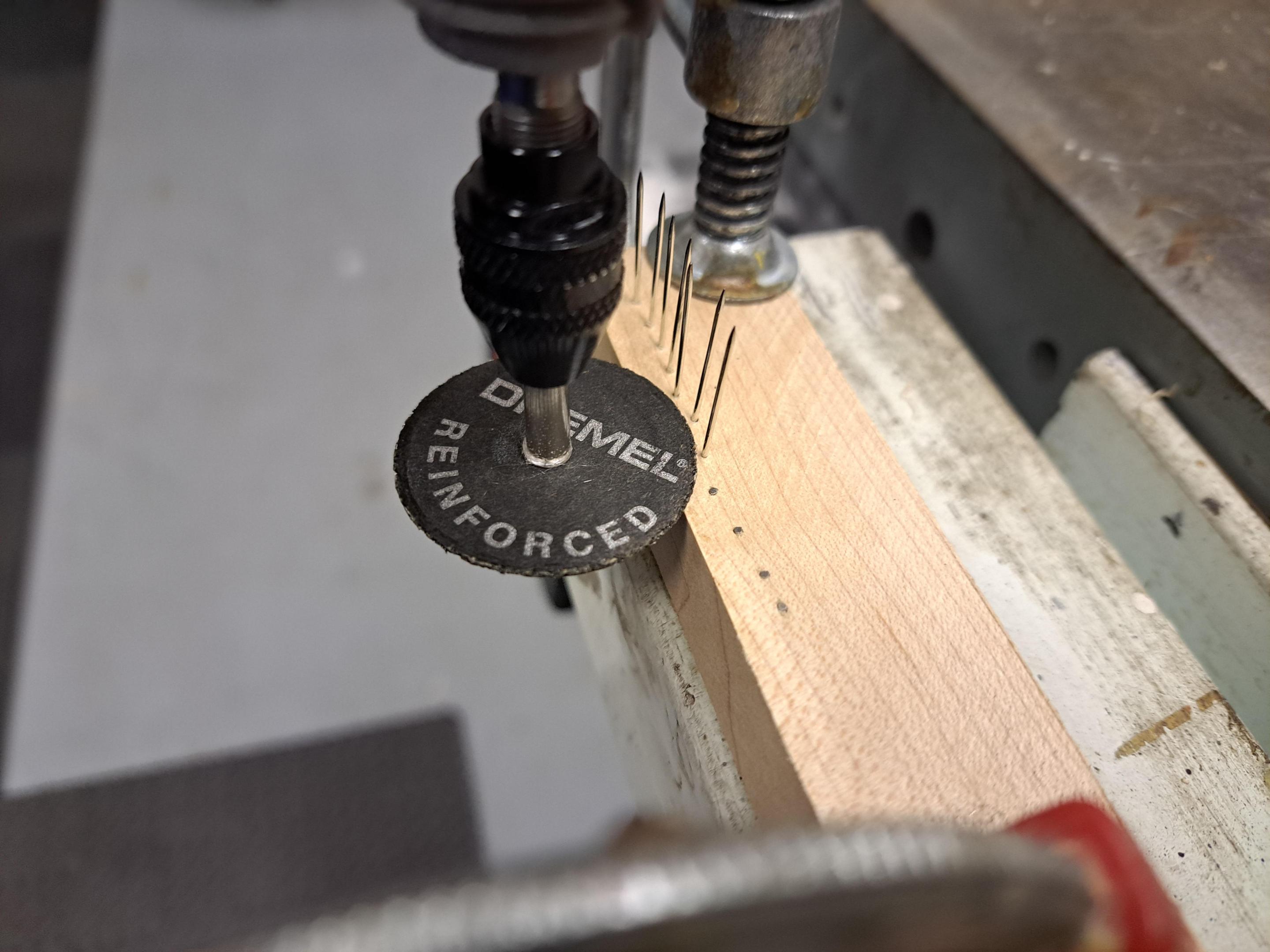
To make the valve stems, I used flat headed stainless steel needles that I had to cut to the correct lenght (.530in). The lenght has to be precise if I want the valves to seat correvtly. To do this, I made a simple jig using a piece of hardwood that was cut to .530in thick. I then drilled a series of .030in diaand inserted the needles. My dremel with a cutting disk made quick work of it. I also made a small jig to cut the valve springs to lenght.
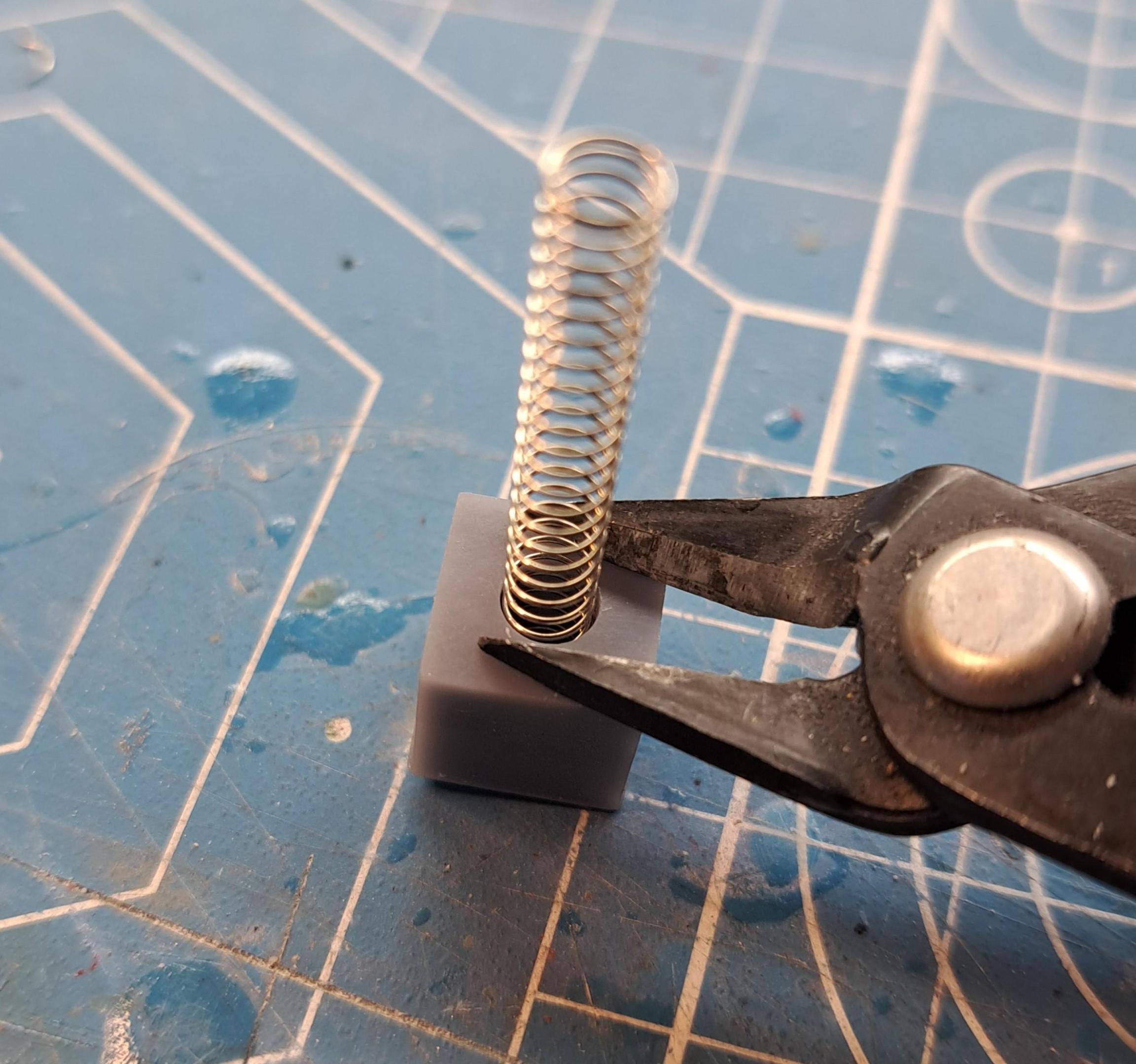
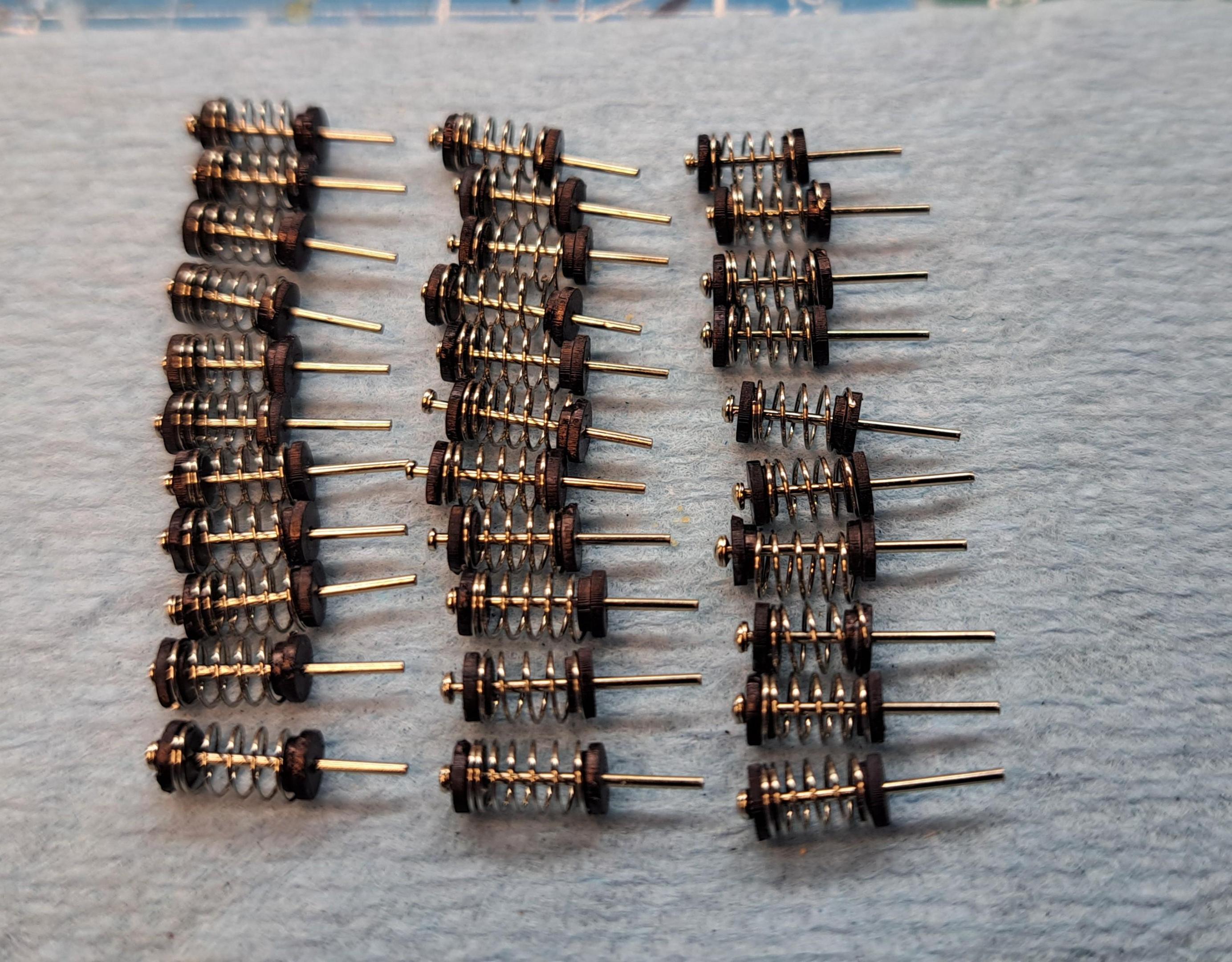
All valve components ready for assembly

And assembled
Painted camshaft

head assembled
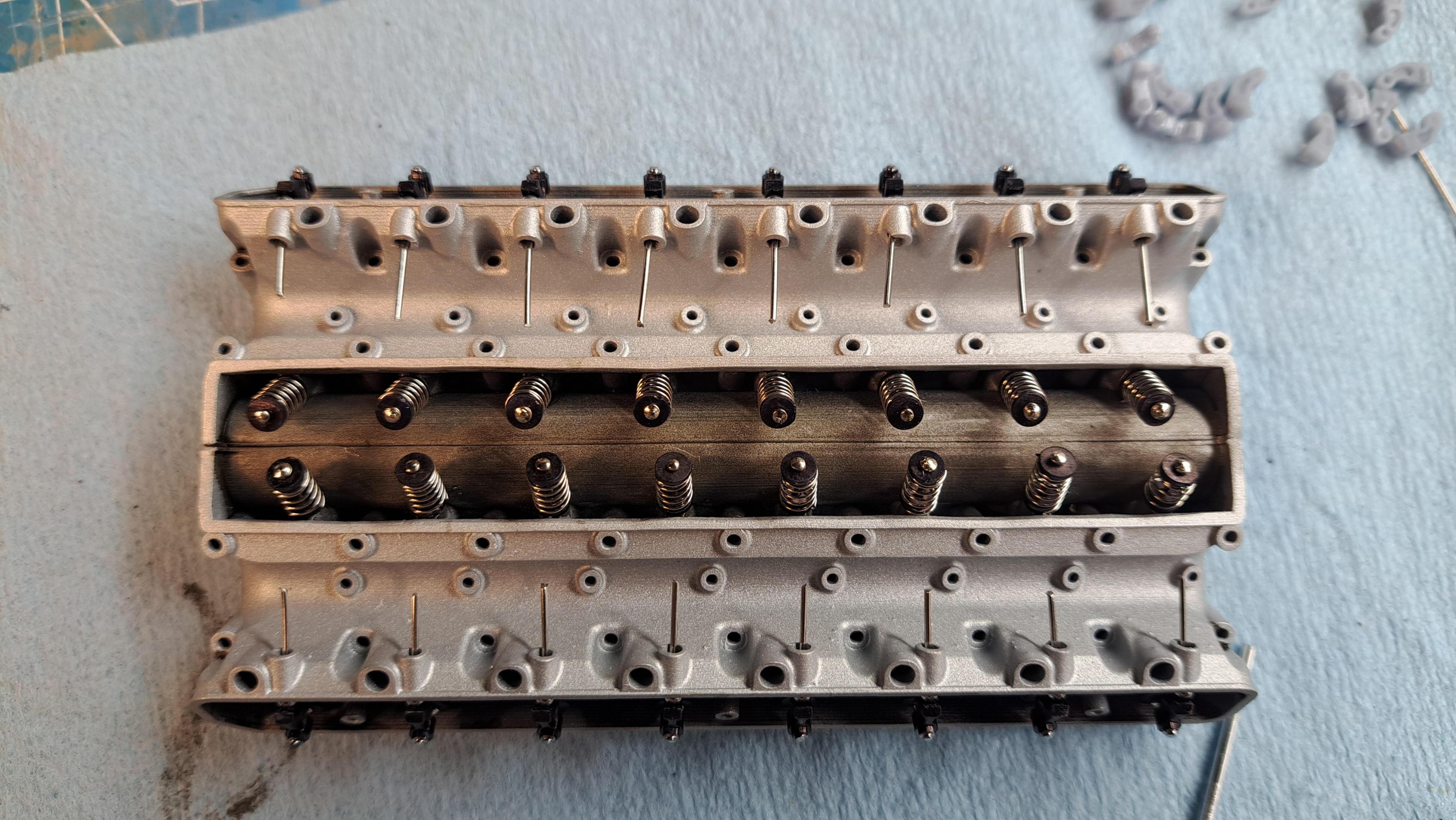


remember, this is not a kit!!
I also made 16 aluminium push rods with spherical heads at both ends. These rods need to be exactly 1.000in long with both spheres in place, I was able to get them all within +- .002in.

To make the valve stems, I used flat headed stainless steel needles that I had to cut to the correct lenght (.530in). The lenght has to be precise if I want the valves to seat correvtly. To do this, I made a simple jig using a piece of hardwood that was cut to .530in thick. I then drilled a series of .030in diaand inserted the needles. My dremel with a cutting disk made quick work of it. I also made a small jig to cut the valve springs to lenght.


All valve components ready for assembly

And assembled

Painted camshaft

head assembled


remember, this is not a kit!!
Now you owned a VERY BIG WOW, François. Impressive scale technique.I made good progress on the head today. All 32 valves are made and in place, painted the head casting flat aluminium and added some engine grime in the concaved areas, assembled and painted the camshaft complete with simulated grounded lobe surfaces (I used a chrome pen for this) and installed the exhaust valve rockers. The black finish on the rockers is done with a permanent marker, easy to apply, close to zero thickness and dries very fast.
I also made 16 aluminium push rods with spherical heads at both ends. These rods need to be exactly 1.000in long with both spheres in place, I was able to get them all within +- .002in.
To make the valve stems, I used flat headed stainless steel needles that I had to cut to the correct lenght (.530in). The lenght has to be precise if I want the valves to seat correvtly. To do this, I made a simple jig using a piece of hardwood that was cut to .530in thick. I then drilled a series of .030in diaand inserted the needles. My dremel with a cutting disk made quick work of it. I also made a small jig to cut the valve springs to lenght.
All valve components ready for assembly

And assembled
Painted camshaft

head assembled

remember, this is not a kit!!
Regards, Peter
You have created a truly amazing realistic look with that engine head.
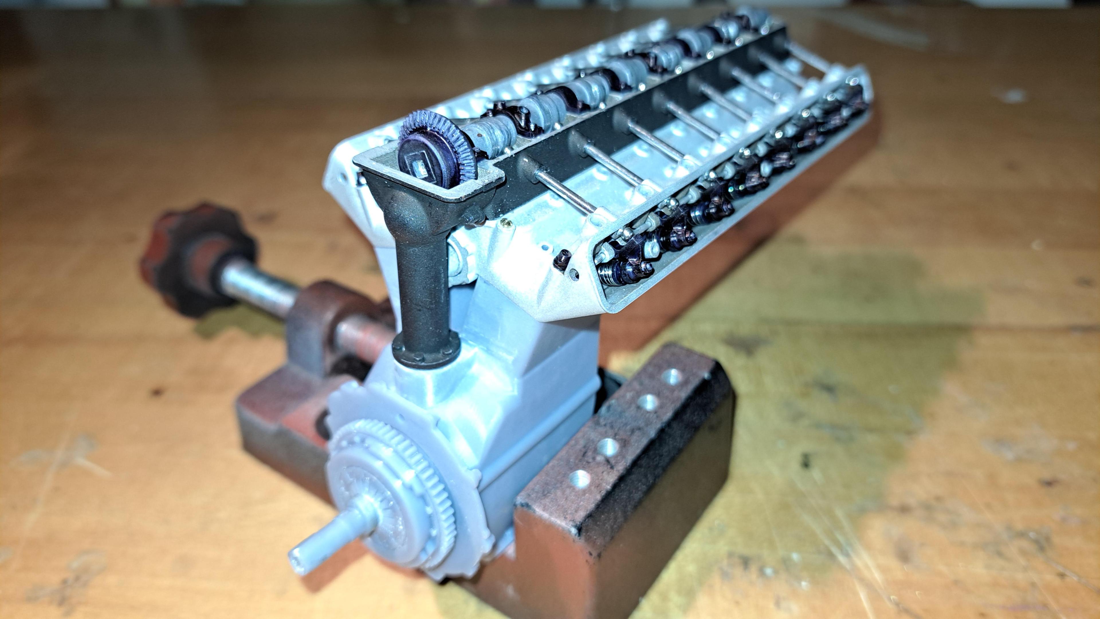
Today marks another step towards a fully working engine. I printed a small portion of the engine bloc, the clutch and the crank bevel gear. The reason fot this is to see if I can rotate the camshaft by rotating the clutch. Here's how the system work. A bevel gear is mounted on the crank shaft which is directly linked to the clutch. This bevel gear rotates a vertical shaft going up to another set of bevel gears mounted on the camshaft. This is exactly the same system as found on the Bentley blower but with a few differences. First, it's a lot bigger, about twice as big. Second and most important difference is that on my Bentley model, these bevel gears rotated a simple shaft acting as the camshaft. Nothing else happens. On the hydra engine, there's an actual camshaft that, if everything goes to plan, will actuate 32 valves. Now we've seen that the valves can be actuated via the camshaft, well at least one can as seen in this little video.
View attachment 20241119_133449~3.mp4
But to have a fully working engine, I need to be able to turn the camshaft by turning the clutch.
So here's the bloc I printed with 2 pistons in place
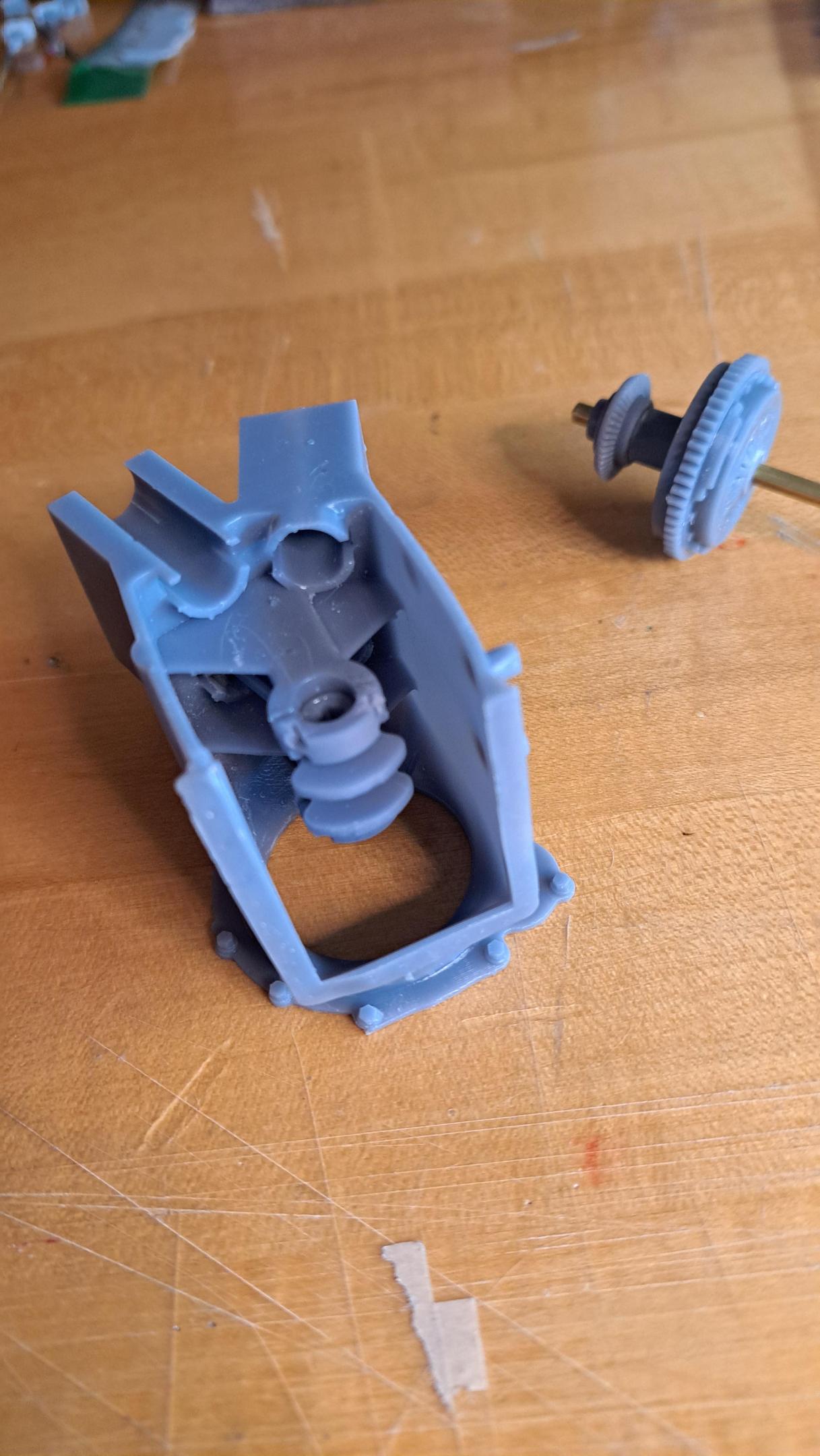
and the clutch
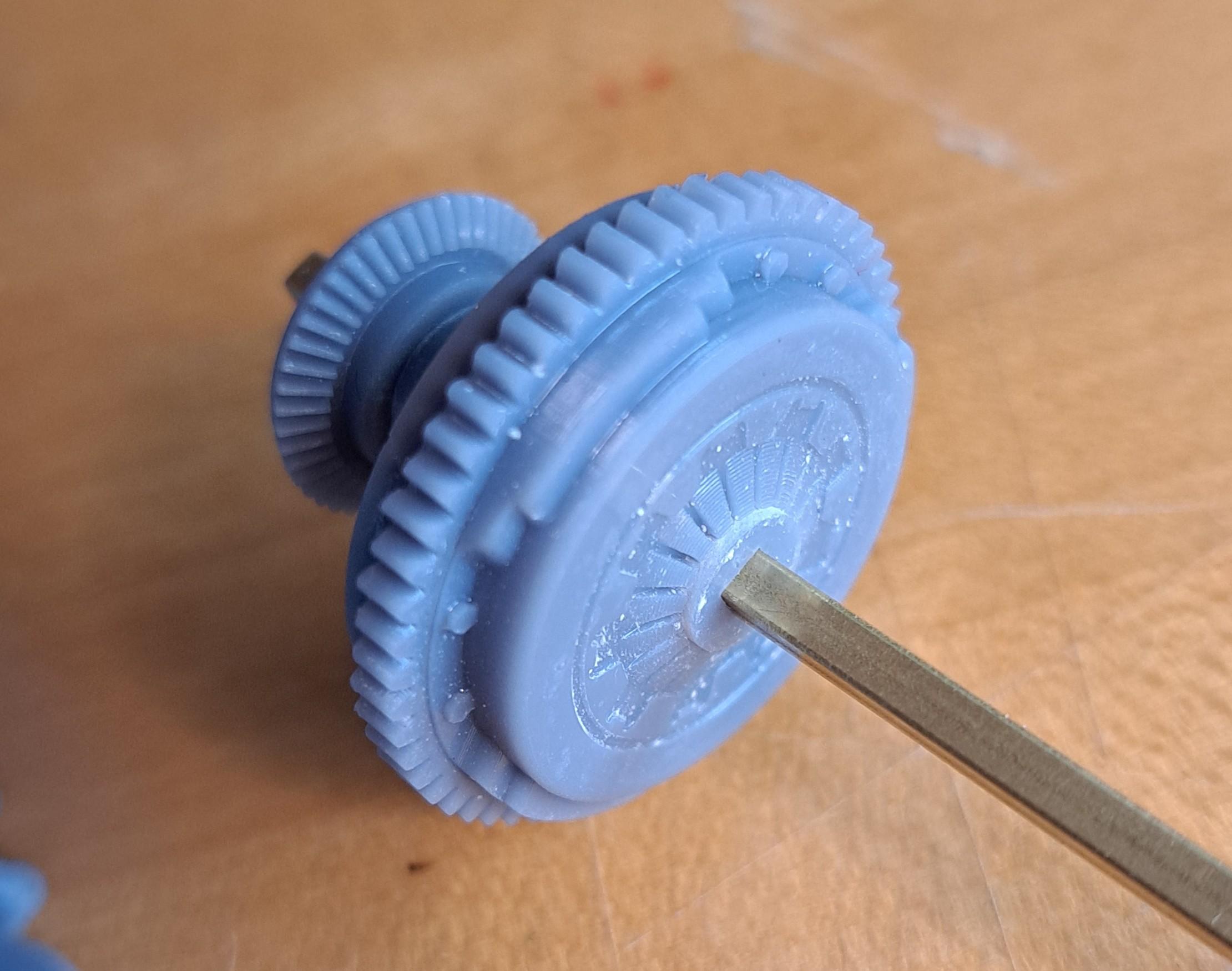
And here's the test I did where I was easily able to turn the camshaft by turning the clutch.
View attachment 20241122_102948.mp4
And a final picture showing the know painted camshaft housing and head bolted on the bloc.
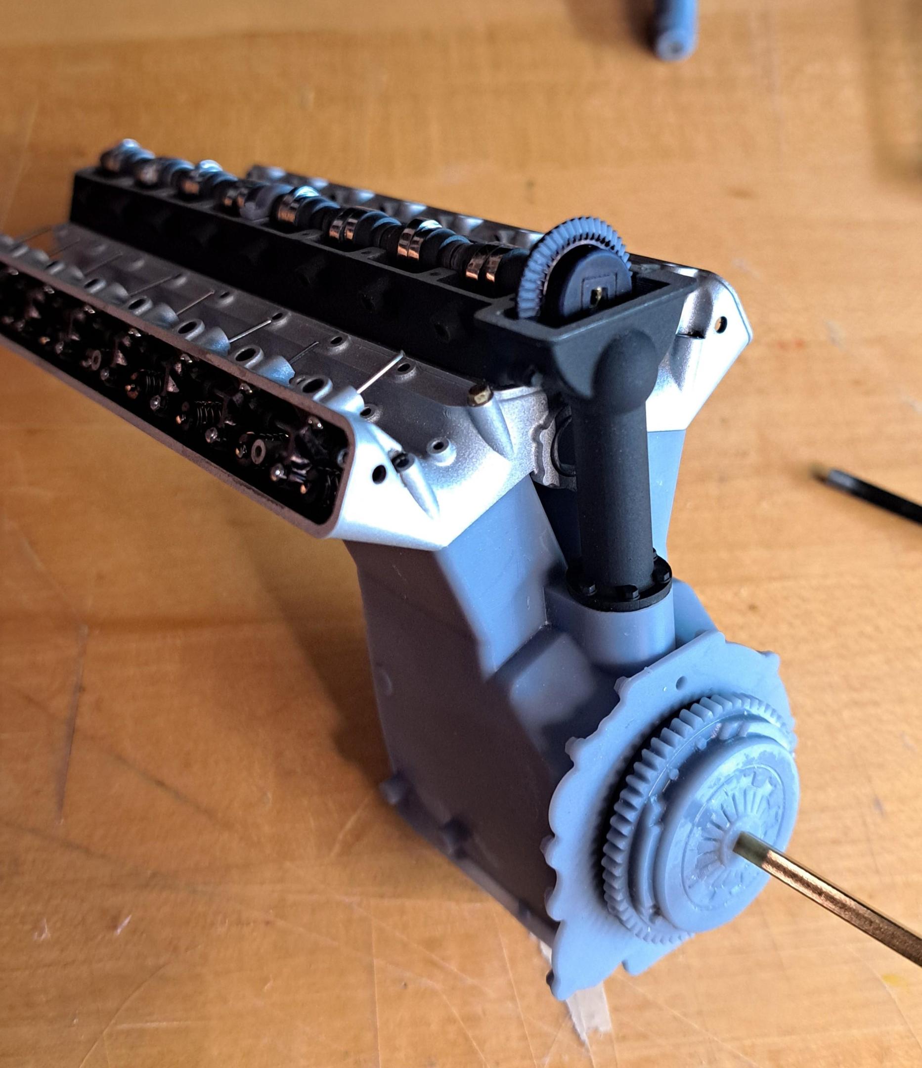
So far so good!
View attachment 20241119_133449~3.mp4
But to have a fully working engine, I need to be able to turn the camshaft by turning the clutch.
So here's the bloc I printed with 2 pistons in place

and the clutch

And here's the test I did where I was easily able to turn the camshaft by turning the clutch.
View attachment 20241122_102948.mp4
And a final picture showing the know painted camshaft housing and head bolted on the bloc.

So far so good!
Awesome work. A little bigger, and you can put it in your Triumph.
Mondrasek, I'm using a Anycubic photon m5s with waterwash resin. Rick, I'm actually thinking of doing the Triumph Tr6 in 1/8 scale as my next car project. Aside from a 1/18 scale die cast, there's nothing out there. A nice big scale model would be fun. After all, I do have a full scale version sitting in the garage so easy enough for me to get the measurements for the 3d model.
I think a 1/8 scale model of the TR6 would be a real winner. I would be very happy to help you market such a kit.
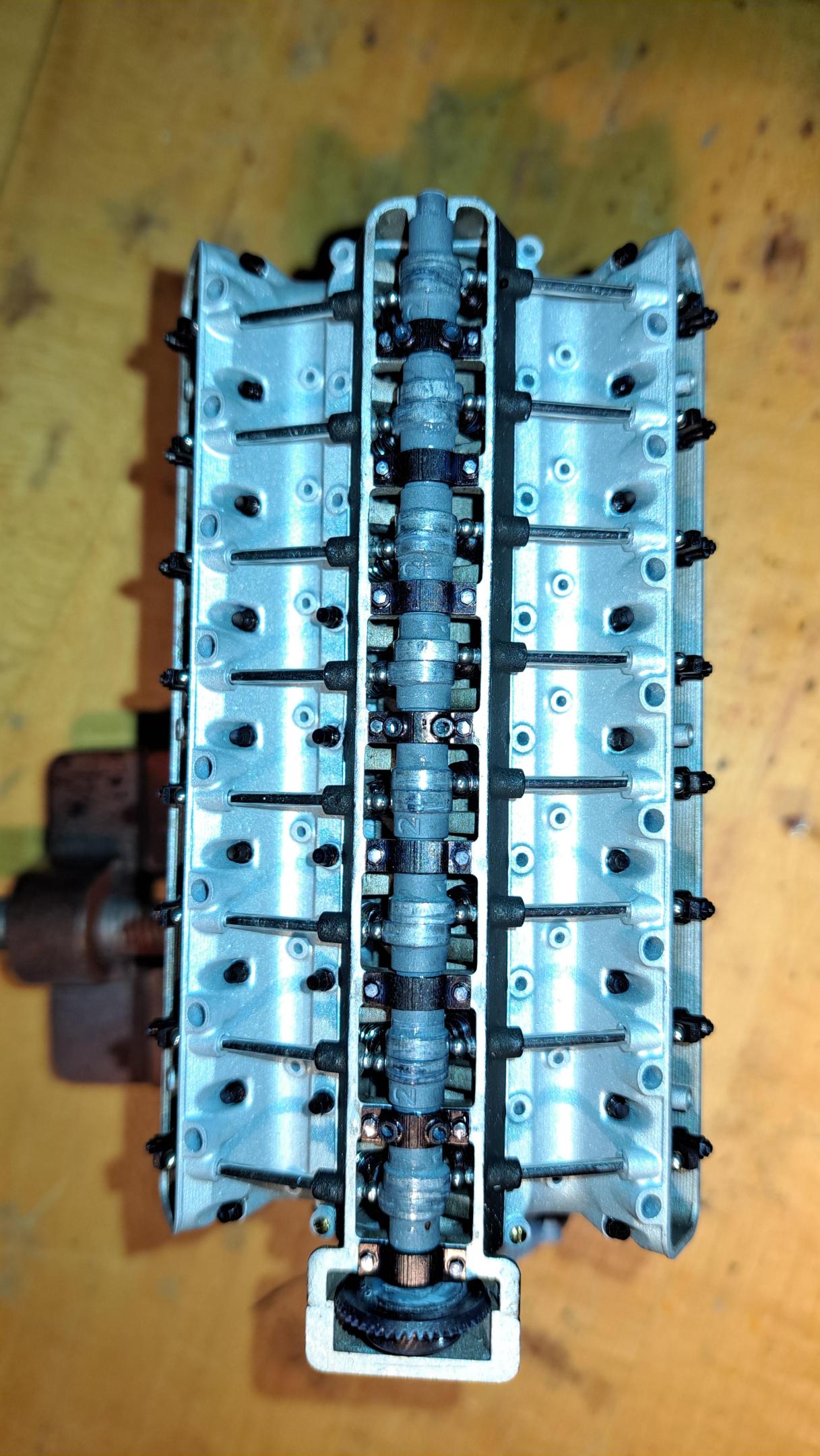
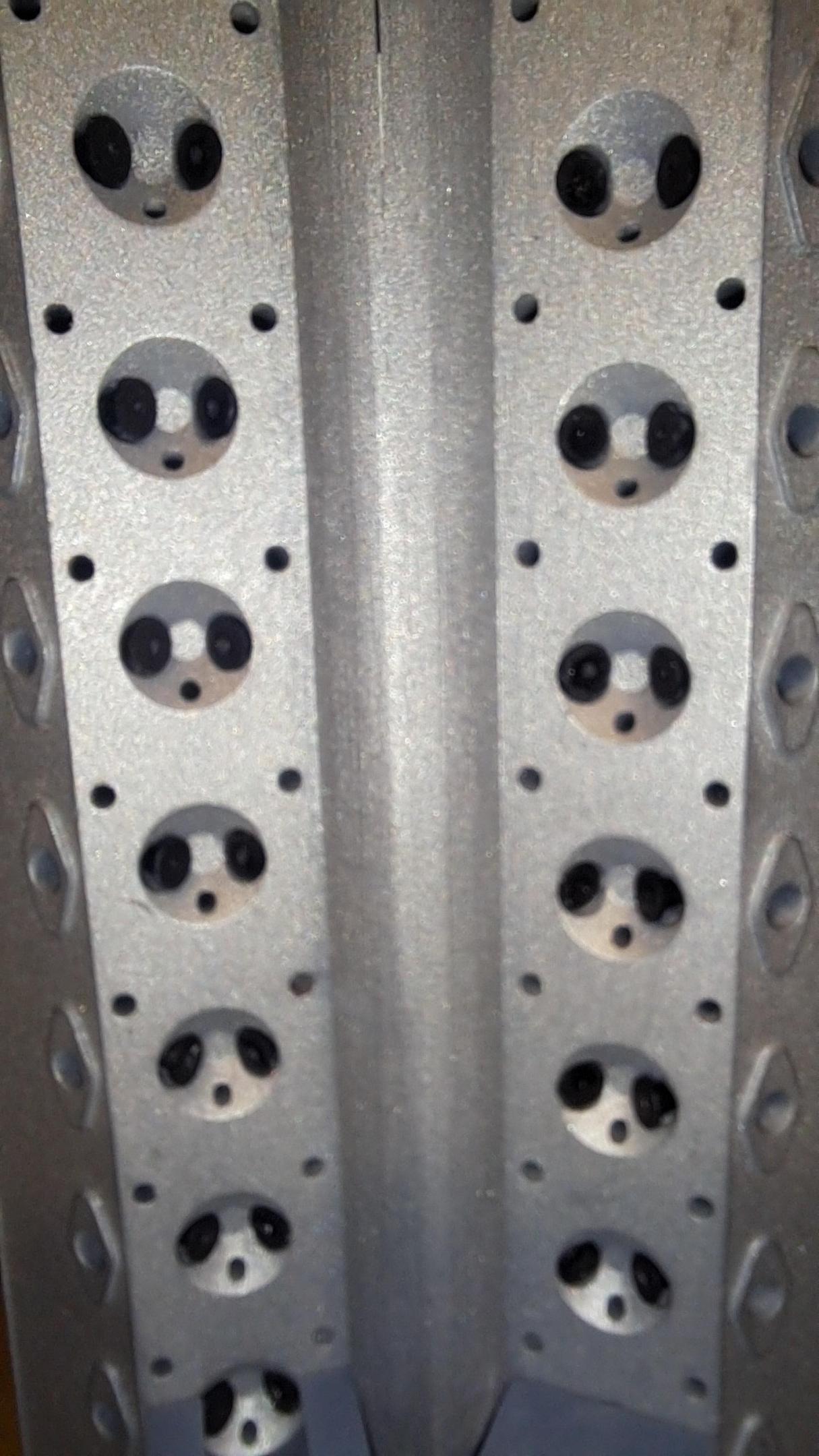
After many hours of testing, modifying, reprinting and assembly, I finally have a fully working 1/12 scale V16 engine head!! 32 valves, 32 rockers, 16 push rods, 1 camshaft and some gearing. All working together. I'm really really happy with the result.
I did have to make certain modifications and compromises.
I redesigned and reprinted all rockers with a different contact face to8 the valves. I also redid all valve spring washers to better guide the springs and finally, I had to shorten all valve springs because there was too much combined pressure on the camshaft to easily rotate it. The drawback to this is that some valves have very little mouvement.
Old rockers and valve on top
New ones on bottom

Some assembly pictures
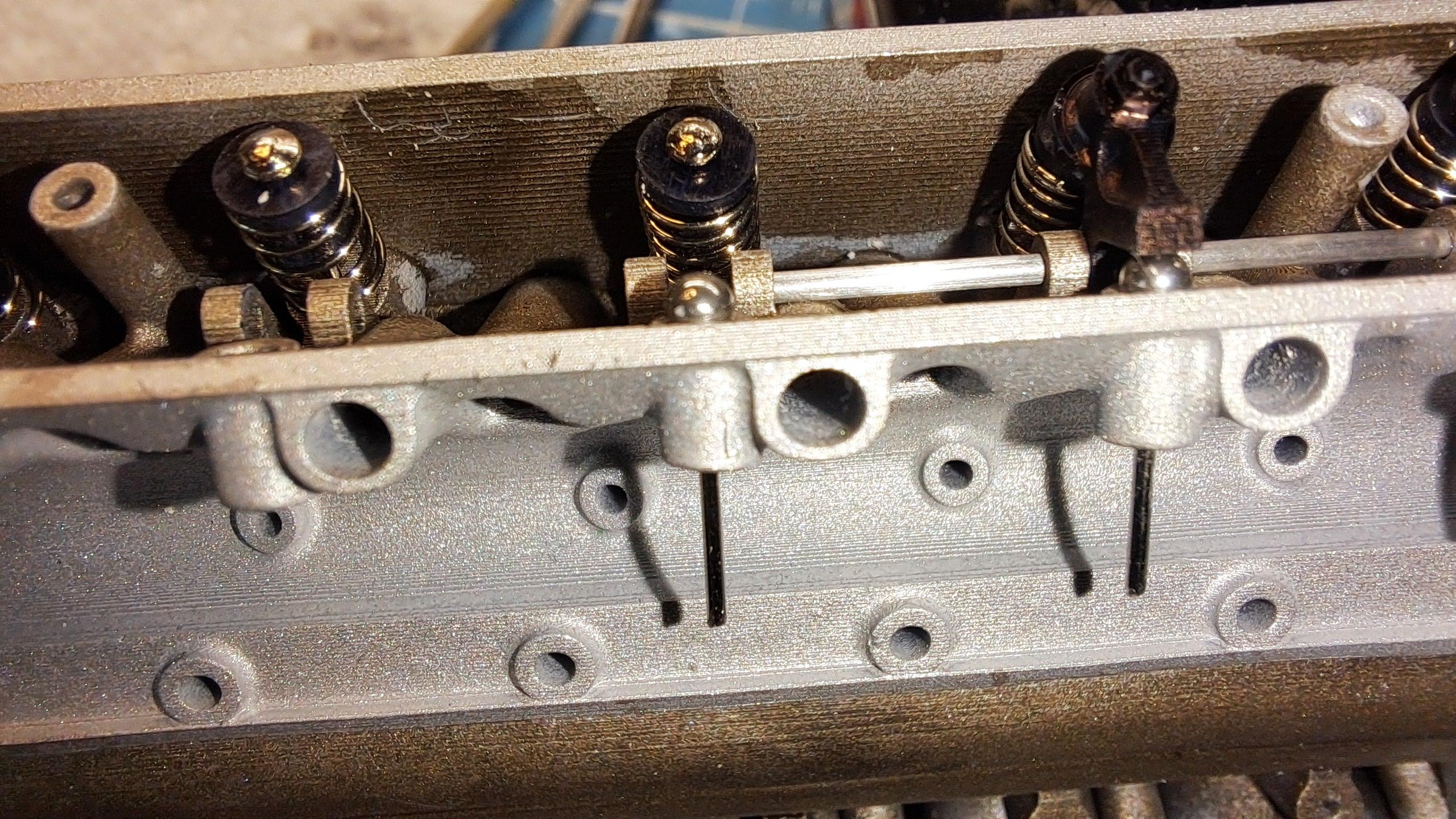
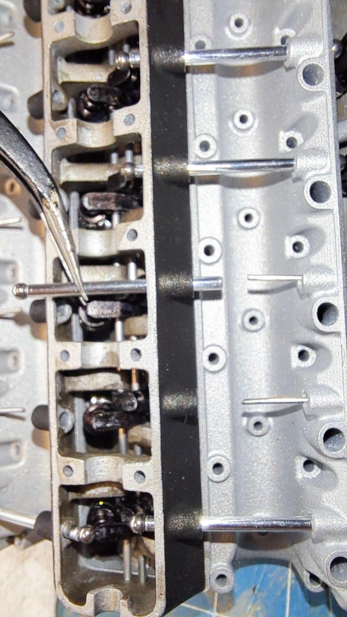
Pictures of completed head


And my 3d model
.jpg.de3605a8ea0cb54a40b5964729e4f18f.jpg)
Video of valves moving, you have to watch very carefully to see the movement
View attachment 20241124_200332.mp4
And video of valve train in action (accelarated x4)
View attachment 20241124_195805~2.mp4
I did have to make certain modifications and compromises.
I redesigned and reprinted all rockers with a different contact face to8 the valves. I also redid all valve spring washers to better guide the springs and finally, I had to shorten all valve springs because there was too much combined pressure on the camshaft to easily rotate it. The drawback to this is that some valves have very little mouvement.
Old rockers and valve on top
New ones on bottom

Some assembly pictures


Pictures of completed head


And my 3d model
.jpg.de3605a8ea0cb54a40b5964729e4f18f.jpg)
Video of valves moving, you have to watch very carefully to see the movement
View attachment 20241124_200332.mp4
And video of valve train in action (accelarated x4)
View attachment 20241124_195805~2.mp4
About 40 years ago I was a newspaper delivery boy in Hampton, Va. One house that I delivered to had a TR6 in the driveway most evenings. I guess the owner drove it as his primary vehicle. It was ORANGE. And stunning. And totally captivated my pre-driving age imagination. I SOOO loved that car and would love one even if in miniature form (with fully operational valvetrain I assume?).
Question. How would you plan to produce the body at that scale? A different printer? Or vacuum form over a mold?
Question. How would you plan to produce the body at that scale? A different printer? Or vacuum form over a mold?
The TR6 is a small car, a little over 12 feet long by not quite 5ft wide. Even at 1/8 scale, it would still be smaller than the 1/12 scale Hydra coupe so the body panels could be printed on my actuel printer. Althought by the time I get do this project, chances are I'll have a bigger printer. Have you seen my Tr6 restoration? the link is in my signature.


