- Joined
- May 8, 2021
- Messages
- 109
- Points
- 78

Part 19 Sponson 4, 3 and 5 Part 3 of 4 parts
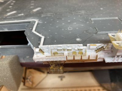
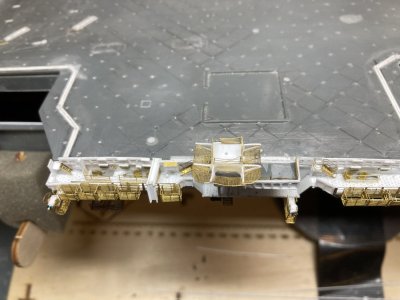
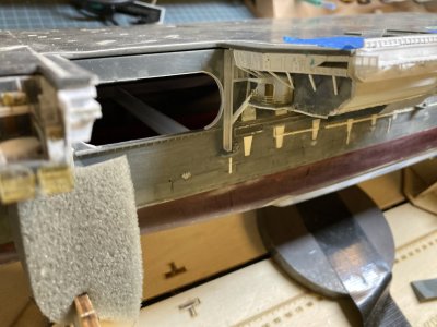
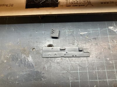
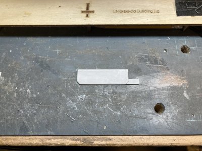
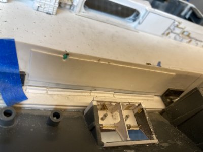
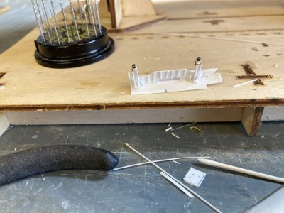
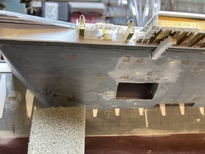
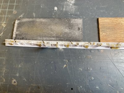
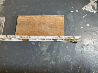
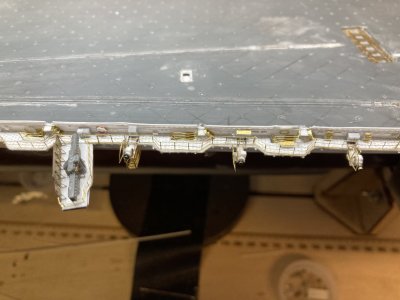
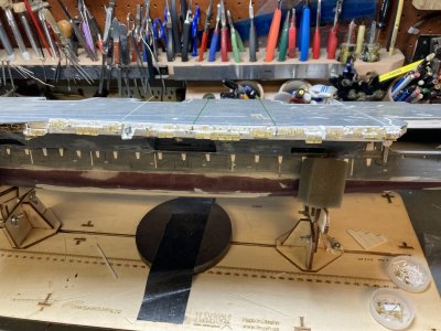
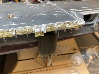
I followed the same basic steps for making the flight deck catwalk for this section using the wider flight deck coaming. I added strip for the scuppers but in this section of the flight deck the coaming was different. I did not put strip above the drain holes in the coaming. Photos show a splinter shield around the edge of the flight deck about thigh high on a 1/350 figure between elevators. There were handrails on top of the shield. I used a piece of .010” X .080” of strip to make the shield. I detailed this with some of the stanchion material for the catwalks. I marked and cut out access openings for ladders to the upper catwalks from the flight deck. The splinter shields were glued to the flight deck coamings leaving the drain holes barely visible. I glued photo etched railing behind the coaming so that the upper rails rise above splinter shield. When I made my drawings I totally missed this feature. I don’t remember it but I was normally standing on the inside looking out and my focus wasn’t on the ship when I was ashore.
I have just done the basics on the catwalk.
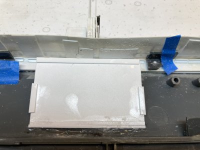
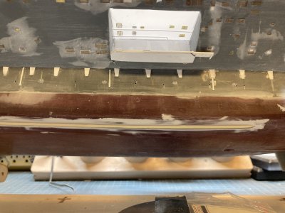
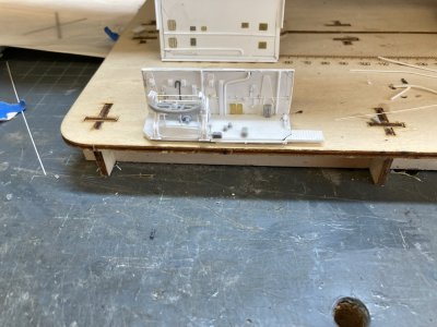
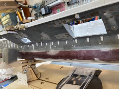
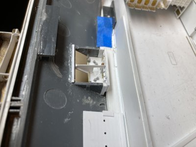
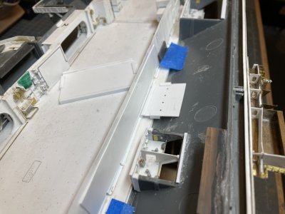
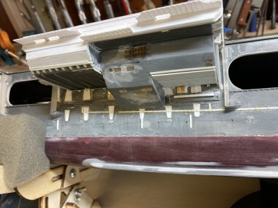
When the Starboard Mk-115 Director was added it was placed on a structure which cantilevered over the lower area of the catwalk. After the big refit when the director was removed, the starboard Phalanx CIWS mount was placed there. I had already filled the locator for the Phalanx mount on my flight deck but the platform the kit supplies was modified so I could use it and more importantly backdate it. The kit part is much larger than the one that was there for the Mk-115. I cut it down a great deal, modified the structure and glued the 2 pedestal structure pieces to the deck of the kit part. I had to skin over the holes on the forward and outboard sides of the pedestal. The same splinter shield railing combination goes around the forward edges of the platform albeit slightly wider to account for the thickness of the deck.
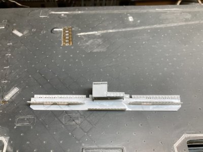
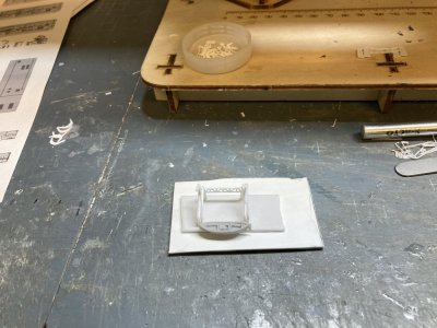
Before. The MK-115 platform is almost done or so I thought.
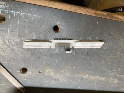
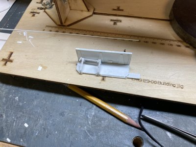
During. It looks pretty bad with everything chopped off.
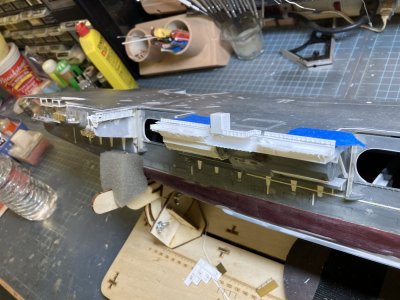
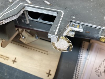
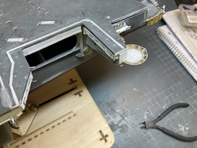
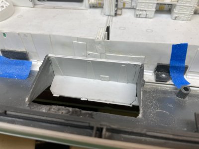
After. The pedestal structure is much smaller now. It extends over the lower catwalk just enough to protrude past the catwalk slightly. Now the supports will be in the right place.
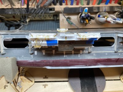
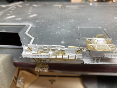
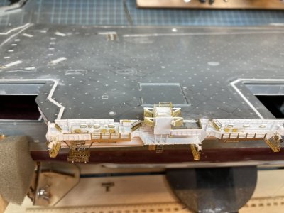
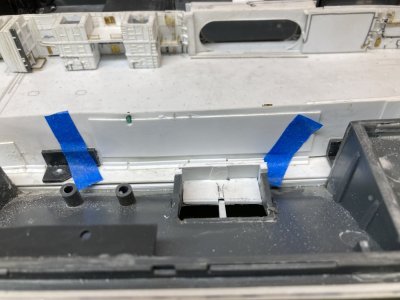
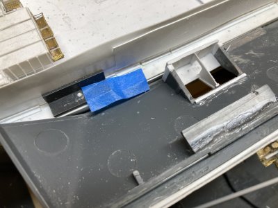
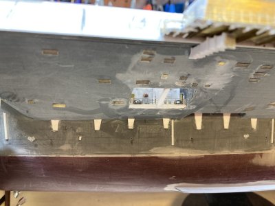
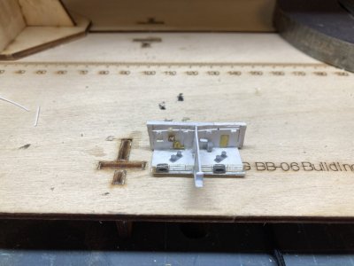
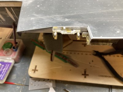
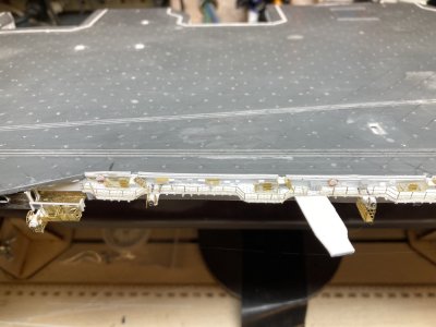
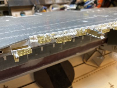
The part was glued to the flight deck coaming and I drilled a hole for a single pin into the edge of the flight deck to help hold the assembly in place. After looking carefully at my original effort I felt the MK-115 pedestal was too wide forward and outboard. I cut away more of the structure and covered the sides again. I have included a before, during and after photo above. I felt the second try was much better. Underneath I added some girders (leftover parts from the elevator skirts). Then I added support webbing from the catwalk parts. I then used wide and narrow open angle braces to brace the upper catwalks like I used on previous sections. I placed end caps on the upper catwalks. I added ladder landings for the catwalk flight deck openings. There is one other gap in the coaming in this area for an ordnance disposal ramp. I made a ramp and cut an opening in the coaming.
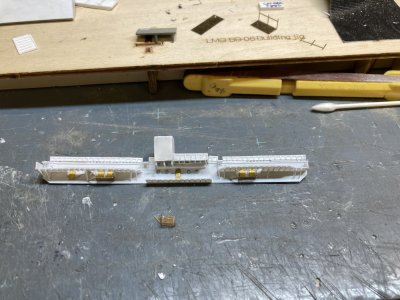
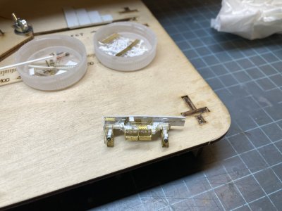
Just the start of the dozens of brass parts.
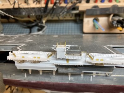
The ladders, pedestal railing and the supports for the pedestal nets are all on.
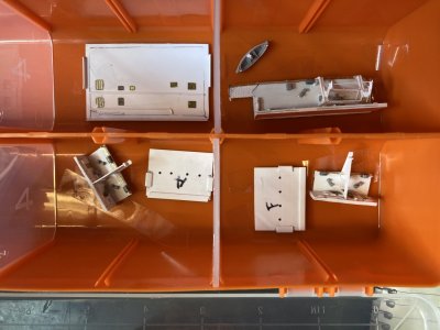
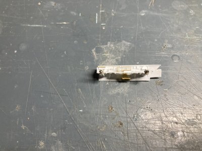
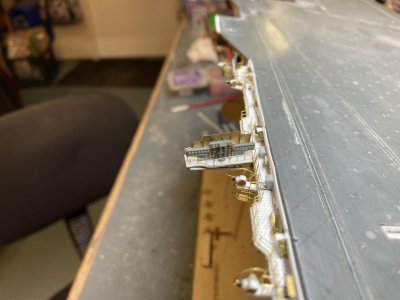
I wanted to see the degree of difficulty that adding the 03 level doors and landings and other photoetch parts. Would they make it too difficult to work with and store the assembly? I folded up the three parts designated by Eduard for these and then they were glued in place. Do be sure to fold these in the correct direction because you only get one bend before they break. The detail side of the deck should be down. I did the first one wrong and spent some time gluing the broken railings back on. If you do it wrong the platform won’t be oriented correctly. The doors on these platforms extend up through the ladder well on the catwalk. On the two platforms with two WTD’s I cut the ladder wells longer so both doors would fit and look somewhat believable. Outside of the ATO I placed a door and 4 portholes.
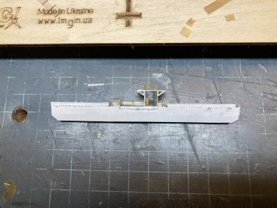
The details on the inboard side of the pedestal.
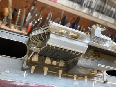
I have just formed, fitted and glued up the 2 corner nets.
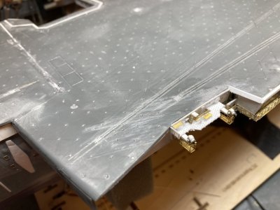
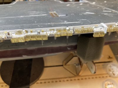
I placed a door and ladder on the inside face of the Mk-115 mount. I glued angle braces for the safety nets and I folded and attached rails around the top. When the net braces had dried sufficiently I reinforced the joins with CA. For the nets I used the White Ensign photoetch for the flight deck nets at the bow. I cut and formed the two corner nets first. I used a ball bearing to get the rounded appearance in the photos and glued them to the corners. Fitting the sides and outboard nets was fairly easy after that.
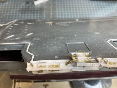
The nets and railings are done.
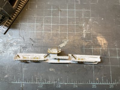
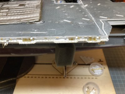
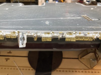
The short ladders from the catwalk to the flight deck have been added
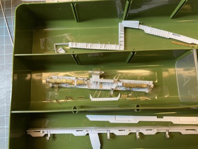
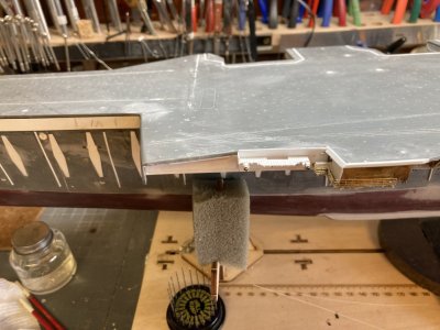
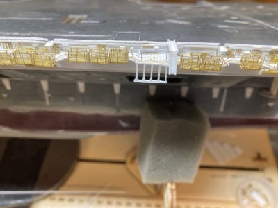
I added the ladders from the catwalk to the flight deck on this section. Even with all of the photoetch installed I was still able to install and remove the catwalk. One other peculiarity of this section of catwalk was the railing and ladders coming off the flight deck just around the island. They had handrails around the ladder platform and the ladder handrails were installed. This must have been a concession for dignitaries coming up from ATO. No other ladder to the flight deck has these features. Aircraft are parked with their tails over the catwalks and a normal handrail on a ladder would just be an accident waiting to happen. With the island blocking aircraft parking this wouldn’t be an issue. Eduard didn’t provide any short ladders from the flight deck or the ladders to the ATO landing but they did supply the other landings and the ladders to them. I had difficulty folding the Eduard ladders 2 of the 3 skewed with the rungs all at a slant. I was using a photoetch folding tool and I am not sure what made them do that. When I tried to correct this both ladders broke. I made 5 ladders using Tom’s Modelworks photoetch but did not install them yet.
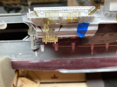
The ladder and cage in position. I had to do some fudging with the locations of some of the parts to fit it all. I used a plastic angle on the opposite end of the small platform because the brass one interfered with the ladder and cage.
I glued the ladder for the outer rigging platform to the coaming above it then checked to make sure that it was all lined up. Next I rolled the ladder cage and promptly lost it somewhere! I looked but couldn’t find it so I used some of the cage from one of the other sets. I ended up cutting away the brace on the single landing because it wouldn’t allow the cage to fit. Hopefully I will find the Eduard part before I return to the long port catwalk because I will need one over the platform there. (Never did find it even after finishing this section and cleaning the bench).
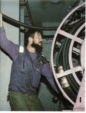
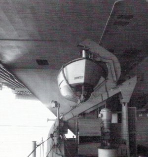
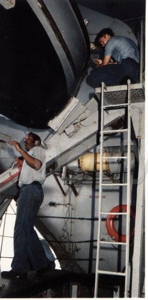
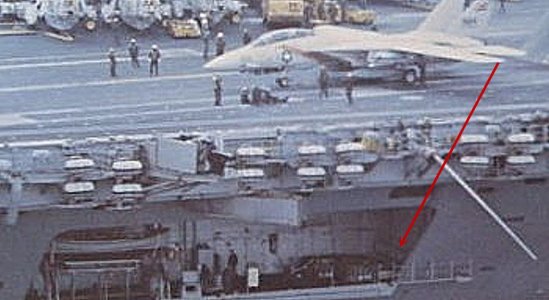
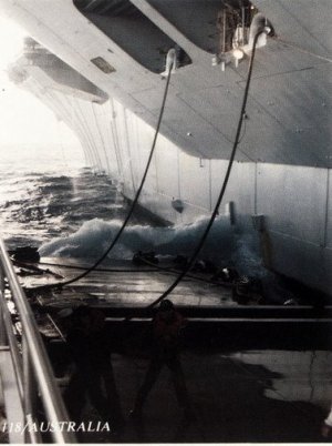
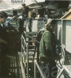
This photo is the only shot of one of these stations that I have.
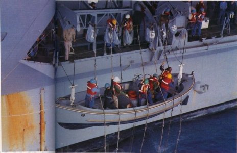
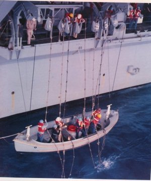
This is something I just recently discovered. I almost always worked nights on the bow or the Six Pack where our planes were usually parked and did not spend a lot of time exploring the other areas. You could miss a lot of what was going on around you because it was so dark. I knew that there were fuel hose reels under the flight deck because of the photo showing one that has been in my collection for some time. I really didn’t know where they all were though. That is a detail that is wrong in both kits as they have you assemble and place several hose reels in the catwalks where they never were.
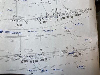
This step from the Tamiya instructions shows assembled hose reels going in the catwalks on the port and starboard midships catwalks. All of these locations are in error. There should not be any hose reels in any of these places. The equivalent page from the Mini Hobby kit is too difficult to read but it shows the same mistakes.
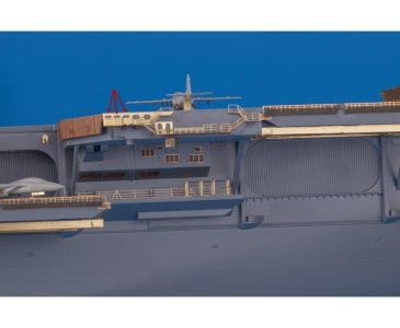
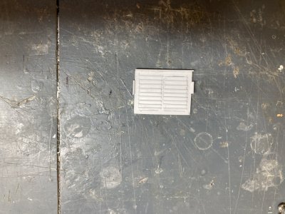
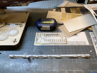
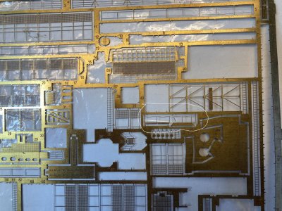
This is the Eduard photoetch for the catwalk between Elevator 1 and 2. The arrows point out the fuel station windows. Unfortunately this is the only piece in their set that represents this feature. They don’t supply the rollers either.
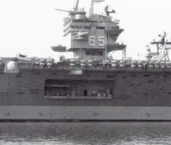
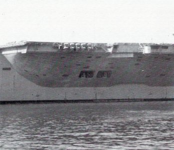
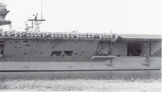
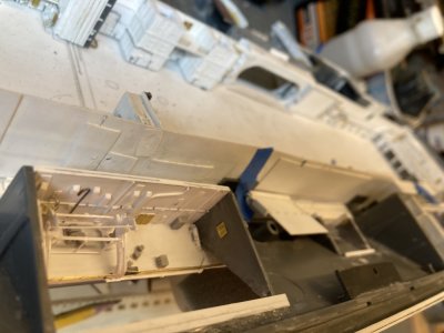
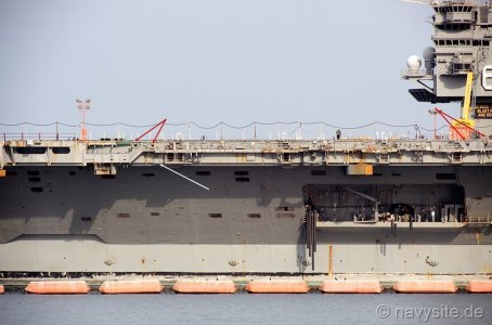
All the midships fuel hoses are below the flight deck in the 03 level If you don’t know what you are looking for you will miss them entirely. They can be spotted by the rollers on the coaming and directly below the roller there will be a horizontal oval opening. In the photos it appears black. The Eduard Part 5 set provides a photoetched part that represents some of these but only in the catwalk between Elevator 1 and 2. Another giveaway in these locations is a landing with two doors. One door is access to the fuel station and the other leads to the interior of the ship.
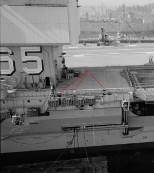
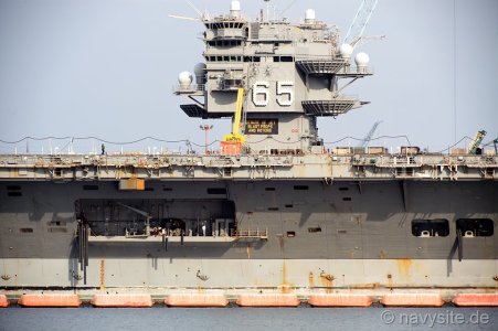
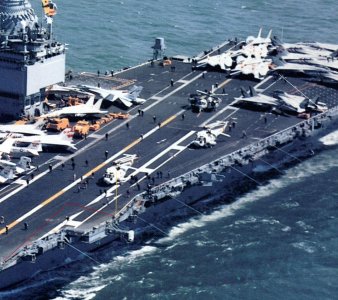
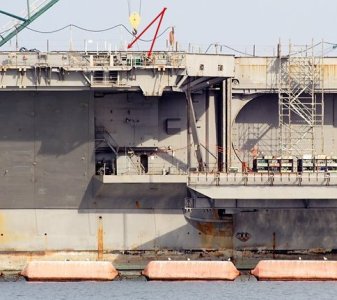
These are the fuel stations forward of the island. The red arrows point to the fuel stations. Note the double rollers on these stations because of the high coaming. Where the fuel reels are right in the catwalk there is only one.
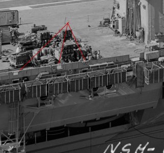
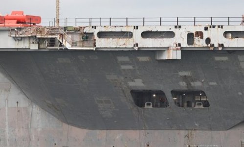
These are the stations aft of the island. There are holes in the coaming but I did not try to duplicate this.
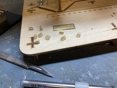
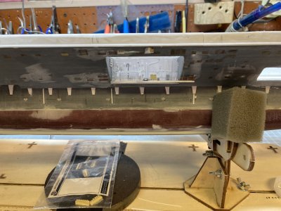
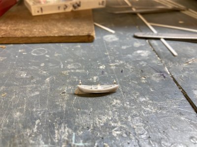
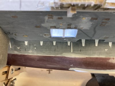
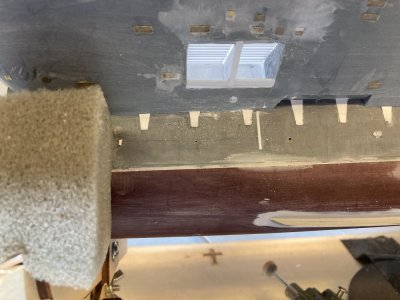
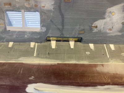
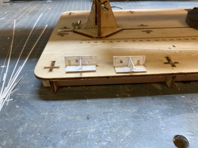
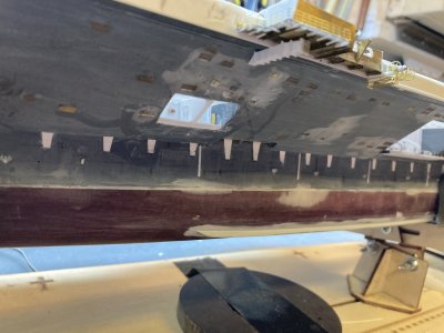
Making the rollers was fairly easy. I cut equal sized pieces of rod and glued them in place. I needed to represent 6 oval windows in the catwalks between Elevator 2 and 3. To model the oval I decided to make oval rings from plastic tube and just paint the ovals in. The plastic tube just crumpled when I tried to flatten it. I tried something more durable and used some 3/32” K&L brass tube. I first drilled out a section about 1 ½ inches long to thin out the inner diameter. I cult fine slices off it by chucking it in a drill and cutting slices off with a sharp Xacto knife as the drill spun the tube. They were too thick so I sanded them between 2 pieces of 220 grit sandpaper glued to wood shims until they were wafer thin. I slipped each ring over a tapered piece of .030” X .060” strip. By forcing them down the strip they take on the flat oval shape which I finished by squeezing them with pliers. These were then located in the catwalks and glued down.
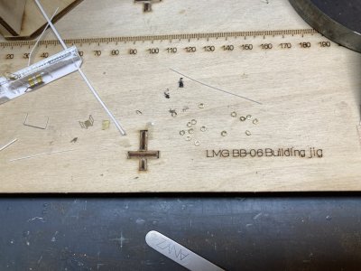
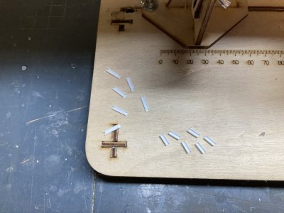
I have cut many more rings than I need because I will need them in other portions of the catwalks. It still seems odd that I did not lose any.
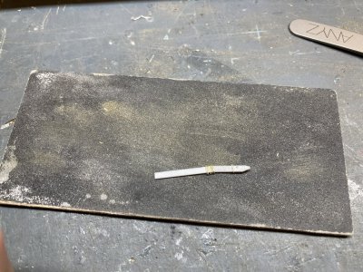
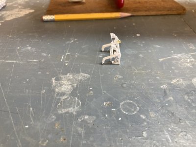
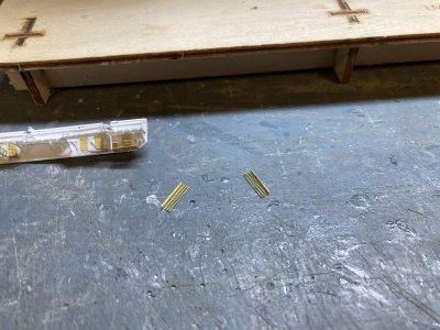
These are the rings on the tapered jig you can see how much thinner they are now.
This is the end of part 3.
I followed the same basic steps for making the flight deck catwalk for this section using the wider flight deck coaming. I added strip for the scuppers but in this section of the flight deck the coaming was different. I did not put strip above the drain holes in the coaming. Photos show a splinter shield around the edge of the flight deck about thigh high on a 1/350 figure between elevators. There were handrails on top of the shield. I used a piece of .010” X .080” of strip to make the shield. I detailed this with some of the stanchion material for the catwalks. I marked and cut out access openings for ladders to the upper catwalks from the flight deck. The splinter shields were glued to the flight deck coamings leaving the drain holes barely visible. I glued photo etched railing behind the coaming so that the upper rails rise above splinter shield. When I made my drawings I totally missed this feature. I don’t remember it but I was normally standing on the inside looking out and my focus wasn’t on the ship when I was ashore.
I have just done the basics on the catwalk.
When the Starboard Mk-115 Director was added it was placed on a structure which cantilevered over the lower area of the catwalk. After the big refit when the director was removed, the starboard Phalanx CIWS mount was placed there. I had already filled the locator for the Phalanx mount on my flight deck but the platform the kit supplies was modified so I could use it and more importantly backdate it. The kit part is much larger than the one that was there for the Mk-115. I cut it down a great deal, modified the structure and glued the 2 pedestal structure pieces to the deck of the kit part. I had to skin over the holes on the forward and outboard sides of the pedestal. The same splinter shield railing combination goes around the forward edges of the platform albeit slightly wider to account for the thickness of the deck.
Before. The MK-115 platform is almost done or so I thought.
During. It looks pretty bad with everything chopped off.
After. The pedestal structure is much smaller now. It extends over the lower catwalk just enough to protrude past the catwalk slightly. Now the supports will be in the right place.
The part was glued to the flight deck coaming and I drilled a hole for a single pin into the edge of the flight deck to help hold the assembly in place. After looking carefully at my original effort I felt the MK-115 pedestal was too wide forward and outboard. I cut away more of the structure and covered the sides again. I have included a before, during and after photo above. I felt the second try was much better. Underneath I added some girders (leftover parts from the elevator skirts). Then I added support webbing from the catwalk parts. I then used wide and narrow open angle braces to brace the upper catwalks like I used on previous sections. I placed end caps on the upper catwalks. I added ladder landings for the catwalk flight deck openings. There is one other gap in the coaming in this area for an ordnance disposal ramp. I made a ramp and cut an opening in the coaming.
Just the start of the dozens of brass parts.
The ladders, pedestal railing and the supports for the pedestal nets are all on.
I wanted to see the degree of difficulty that adding the 03 level doors and landings and other photoetch parts. Would they make it too difficult to work with and store the assembly? I folded up the three parts designated by Eduard for these and then they were glued in place. Do be sure to fold these in the correct direction because you only get one bend before they break. The detail side of the deck should be down. I did the first one wrong and spent some time gluing the broken railings back on. If you do it wrong the platform won’t be oriented correctly. The doors on these platforms extend up through the ladder well on the catwalk. On the two platforms with two WTD’s I cut the ladder wells longer so both doors would fit and look somewhat believable. Outside of the ATO I placed a door and 4 portholes.
The details on the inboard side of the pedestal.
I have just formed, fitted and glued up the 2 corner nets.
I placed a door and ladder on the inside face of the Mk-115 mount. I glued angle braces for the safety nets and I folded and attached rails around the top. When the net braces had dried sufficiently I reinforced the joins with CA. For the nets I used the White Ensign photoetch for the flight deck nets at the bow. I cut and formed the two corner nets first. I used a ball bearing to get the rounded appearance in the photos and glued them to the corners. Fitting the sides and outboard nets was fairly easy after that.
The nets and railings are done.
The short ladders from the catwalk to the flight deck have been added
I added the ladders from the catwalk to the flight deck on this section. Even with all of the photoetch installed I was still able to install and remove the catwalk. One other peculiarity of this section of catwalk was the railing and ladders coming off the flight deck just around the island. They had handrails around the ladder platform and the ladder handrails were installed. This must have been a concession for dignitaries coming up from ATO. No other ladder to the flight deck has these features. Aircraft are parked with their tails over the catwalks and a normal handrail on a ladder would just be an accident waiting to happen. With the island blocking aircraft parking this wouldn’t be an issue. Eduard didn’t provide any short ladders from the flight deck or the ladders to the ATO landing but they did supply the other landings and the ladders to them. I had difficulty folding the Eduard ladders 2 of the 3 skewed with the rungs all at a slant. I was using a photoetch folding tool and I am not sure what made them do that. When I tried to correct this both ladders broke. I made 5 ladders using Tom’s Modelworks photoetch but did not install them yet.
The ladder and cage in position. I had to do some fudging with the locations of some of the parts to fit it all. I used a plastic angle on the opposite end of the small platform because the brass one interfered with the ladder and cage.
I glued the ladder for the outer rigging platform to the coaming above it then checked to make sure that it was all lined up. Next I rolled the ladder cage and promptly lost it somewhere! I looked but couldn’t find it so I used some of the cage from one of the other sets. I ended up cutting away the brace on the single landing because it wouldn’t allow the cage to fit. Hopefully I will find the Eduard part before I return to the long port catwalk because I will need one over the platform there. (Never did find it even after finishing this section and cleaning the bench).
This photo is the only shot of one of these stations that I have.
This is something I just recently discovered. I almost always worked nights on the bow or the Six Pack where our planes were usually parked and did not spend a lot of time exploring the other areas. You could miss a lot of what was going on around you because it was so dark. I knew that there were fuel hose reels under the flight deck because of the photo showing one that has been in my collection for some time. I really didn’t know where they all were though. That is a detail that is wrong in both kits as they have you assemble and place several hose reels in the catwalks where they never were.
This step from the Tamiya instructions shows assembled hose reels going in the catwalks on the port and starboard midships catwalks. All of these locations are in error. There should not be any hose reels in any of these places. The equivalent page from the Mini Hobby kit is too difficult to read but it shows the same mistakes.
This is the Eduard photoetch for the catwalk between Elevator 1 and 2. The arrows point out the fuel station windows. Unfortunately this is the only piece in their set that represents this feature. They don’t supply the rollers either.
All the midships fuel hoses are below the flight deck in the 03 level If you don’t know what you are looking for you will miss them entirely. They can be spotted by the rollers on the coaming and directly below the roller there will be a horizontal oval opening. In the photos it appears black. The Eduard Part 5 set provides a photoetched part that represents some of these but only in the catwalk between Elevator 1 and 2. Another giveaway in these locations is a landing with two doors. One door is access to the fuel station and the other leads to the interior of the ship.
These are the fuel stations forward of the island. The red arrows point to the fuel stations. Note the double rollers on these stations because of the high coaming. Where the fuel reels are right in the catwalk there is only one.
These are the stations aft of the island. There are holes in the coaming but I did not try to duplicate this.
Making the rollers was fairly easy. I cut equal sized pieces of rod and glued them in place. I needed to represent 6 oval windows in the catwalks between Elevator 2 and 3. To model the oval I decided to make oval rings from plastic tube and just paint the ovals in. The plastic tube just crumpled when I tried to flatten it. I tried something more durable and used some 3/32” K&L brass tube. I first drilled out a section about 1 ½ inches long to thin out the inner diameter. I cult fine slices off it by chucking it in a drill and cutting slices off with a sharp Xacto knife as the drill spun the tube. They were too thick so I sanded them between 2 pieces of 220 grit sandpaper glued to wood shims until they were wafer thin. I slipped each ring over a tapered piece of .030” X .060” strip. By forcing them down the strip they take on the flat oval shape which I finished by squeezing them with pliers. These were then located in the catwalks and glued down.
I have cut many more rings than I need because I will need them in other portions of the catwalks. It still seems odd that I did not lose any.
These are the rings on the tapered jig you can see how much thinner they are now.
This is the end of part 3.