• Ships of Scale has incorportated an extra level of security when you log In. Please follow on-screen prompts to acknowledge that you are not a robot via a "Check Box" or a "Pictorial Check Box Puzzle". This is needed due to higher level of AI Activity Security.
  • SUBSCRIBE TO SHIPS IN SCALE TODAY!

    The beloved Ships in Scale Magazine is back and charting a new course for 2026!
    Discover new skills, new techniques, and new inspirations in every issue.

    NOTE THAT OUR NEXT ISSUE WILL BE July/August 2026
  • Win a Free Custom Engraved Brass Coin!!!
    As a way to introduce our brass coins to the community, we will raffle off a free coin during the month of August. Follow link ABOVE for instructions for entering.

Mini Hobby 80502 1/350 Scale USS Enterprise CVN-65 Early

Part 19 Sponson 4, 3 and 5 Part 3 of 4 parts

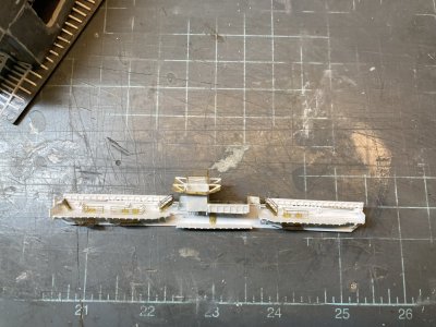
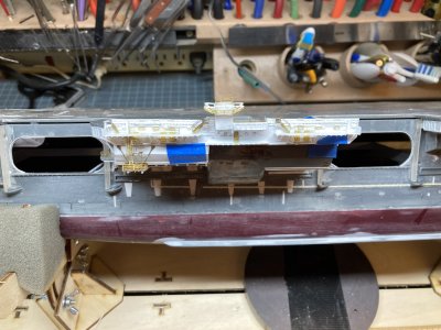
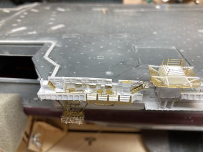
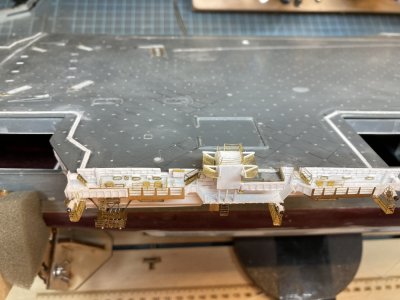
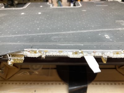
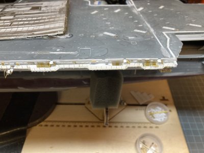
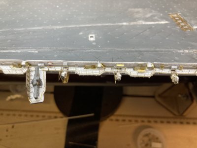
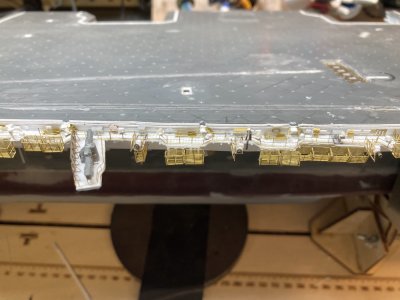
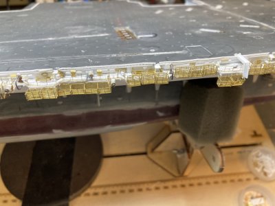
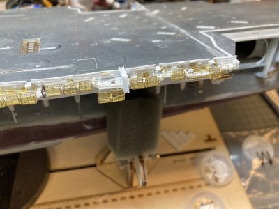
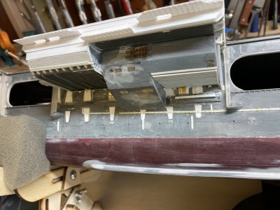
I followed the same basic steps for making the flight deck catwalk for this section using the wider flight deck coaming. I added strip for the scuppers but in this section of the flight deck the coaming was different. I did not put strip above the drain holes in the coaming. Photos show a splinter shield around the edge of the flight deck about thigh high on a 1/350 figure between elevators. There were handrails on top of the shield. I used a piece of .010” X .080” of strip to make the shield. I detailed this with some of the stanchion material for the catwalks. I marked and cut out access openings for ladders to the upper catwalks from the flight deck. The splinter shields were glued to the flight deck coamings leaving the drain holes barely visible. I glued photo etched railing behind the coaming so that the upper rails rise above splinter shield. When I made my drawings I totally missed this feature. I don’t remember it but I was normally standing on the inside looking out and my focus wasn’t on the ship when I was ashore.
Sponson 5 (14).JPG

I have just done the basics on the catwalk.


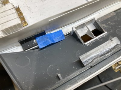
When the Starboard Mk-115 Director was added it was placed on a structure which cantilevered over the lower area of the catwalk. After the big refit when the director was removed, the starboard Phalanx CIWS mount was placed there. I had already filled the locator for the Phalanx mount on my flight deck but the platform the kit supplies was modified so I could use it and more importantly backdate it. The kit part is much larger than the one that was there for the Mk-115. I cut it down a great deal, modified the structure and glued the 2 pedestal structure pieces to the deck of the kit part. I had to skin over the holes on the forward and outboard sides of the pedestal. The same splinter shield railing combination goes around the forward edges of the platform albeit slightly wider to account for the thickness of the deck.
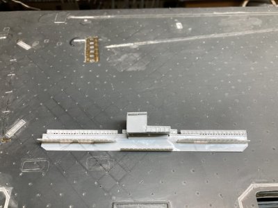
Sponson 5 (18).JPG

Before. The MK-115 platform is almost done or so I thought.
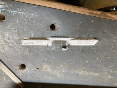
Sponson 5 (33).JPG

During. It looks pretty bad with everything chopped off.
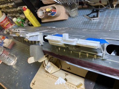
Sponson 5 (37).JPG

After. The pedestal structure is much smaller now. It extends over the lower catwalk just enough to protrude past the catwalk slightly. Now the supports will be in the right place.


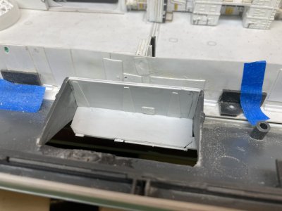
The part was glued to the flight deck coaming and I drilled a hole for a single pin into the edge of the flight deck to help hold the assembly in place. After looking carefully at my original effort I felt the MK-115 pedestal was too wide forward and outboard. I cut away more of the structure and covered the sides again. I have included a before, during and after photo above. I felt the second try was much better. Underneath I added some girders (leftover parts from the elevator skirts). Then I added support webbing from the catwalk parts. I then used wide and narrow open angle braces to brace the upper catwalks like I used on previous sections. I placed end caps on the upper catwalks. I added ladder landings for the catwalk flight deck openings. There is one other gap in the coaming in this area for an ordnance disposal ramp. I made a ramp and cut an opening in the coaming.
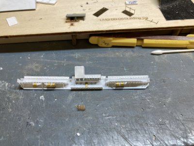
Sponson 5 (41).JPG

Just the start of the dozens of brass parts.
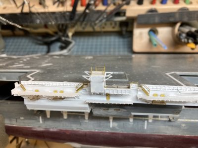
Sponson 5 (47).JPG

The ladders, pedestal railing and the supports for the pedestal nets are all on.


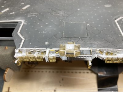
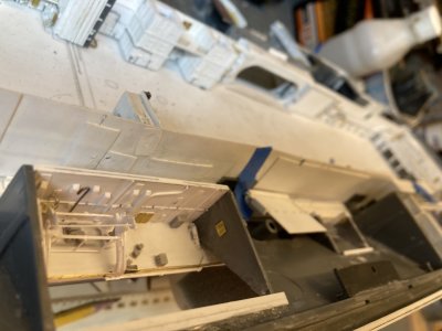
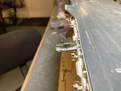
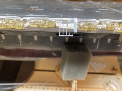
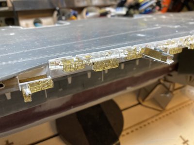
I wanted to see the degree of difficulty that adding the 03 level doors and landings and other photoetch parts. Would they make it too difficult to work with and store the assembly? I folded up the three parts designated by Eduard for these and then they were glued in place. Do be sure to fold these in the correct direction because you only get one bend before they break. The detail side of the deck should be down. I did the first one wrong and spent some time gluing the broken railings back on. If you do it wrong the platform won’t be oriented correctly. The doors on these platforms extend up through the ladder well on the catwalk. On the two platforms with two WTD’s I cut the ladder wells longer so both doors would fit and look somewhat believable. Outside of the ATO I placed a door and 4 portholes.
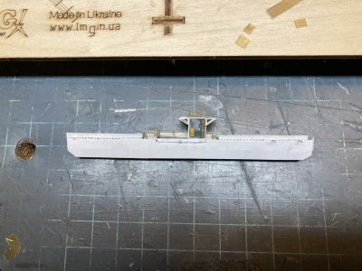
Sponson 5 (53).JPG

The details on the inboard side of the pedestal.
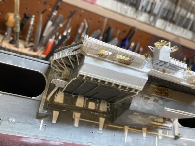
Sponson 5 (51).JPG

I have just formed, fitted and glued up the 2 corner nets.


I placed a door and ladder on the inside face of the Mk-115 mount. I glued angle braces for the safety nets and I folded and attached rails around the top. When the net braces had dried sufficiently I reinforced the joins with CA. For the nets I used the White Ensign photoetch for the flight deck nets at the bow. I cut and formed the two corner nets first. I used a ball bearing to get the rounded appearance in the photos and glued them to the corners. Fitting the sides and outboard nets was fairly easy after that.
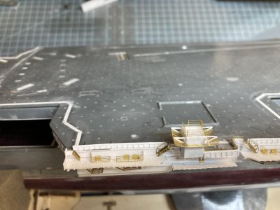
Sponson 5 (56).JPG

The nets and railings are done.

Sponson 5 (87).JPG

The short ladders from the catwalk to the flight deck have been added


I added the ladders from the catwalk to the flight deck on this section. Even with all of the photoetch installed I was still able to install and remove the catwalk. One other peculiarity of this section of catwalk was the railing and ladders coming off the flight deck just around the island. They had handrails around the ladder platform and the ladder handrails were installed. This must have been a concession for dignitaries coming up from ATO. No other ladder to the flight deck has these features. Aircraft are parked with their tails over the catwalks and a normal handrail on a ladder would just be an accident waiting to happen. With the island blocking aircraft parking this wouldn’t be an issue. Eduard didn’t provide any short ladders from the flight deck or the ladders to the ATO landing but they did supply the other landings and the ladders to them. I had difficulty folding the Eduard ladders 2 of the 3 skewed with the rungs all at a slant. I was using a photoetch folding tool and I am not sure what made them do that. When I tried to correct this both ladders broke. I made 5 ladders using Tom’s Modelworks photoetch but did not install them yet.
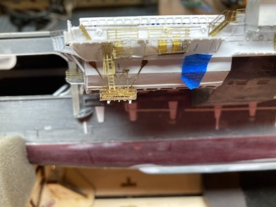
Sponson 5 (99).JPG

The ladder and cage in position. I had to do some fudging with the locations of some of the parts to fit it all. I used a plastic angle on the opposite end of the small platform because the brass one interfered with the ladder and cage.


I glued the ladder for the outer rigging platform to the coaming above it then checked to make sure that it was all lined up. Next I rolled the ladder cage and promptly lost it somewhere! I looked but couldn’t find it so I used some of the cage from one of the other sets. I ended up cutting away the brace on the single landing because it wouldn’t allow the cage to fit. Hopefully I will find the Eduard part before I return to the long port catwalk because I will need one over the platform there. (Never did find it even after finishing this section and cleaning the bench).
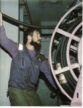
fuel 05.jpg

This photo is the only shot of one of these stations that I have.


This is something I just recently discovered. I almost always worked nights on the bow or the Six Pack where our planes were usually parked and did not spend a lot of time exploring the other areas. You could miss a lot of what was going on around you because it was so dark. I knew that there were fuel hose reels under the flight deck because of the photo showing one that has been in my collection for some time. I really didn’t know where they all were though. That is a detail that is wrong in both kits as they have you assemble and place several hose reels in the catwalks where they never were.
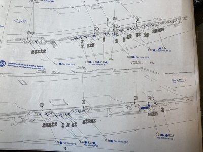
Sponson 5 (101).JPG

This step from the Tamiya instructions shows assembled hose reels going in the catwalks on the port and starboard midships catwalks. All of these locations are in error. There should not be any hose reels in any of these places. The equivalent page from the Mini Hobby kit is too difficult to read but it shows the same mistakes.
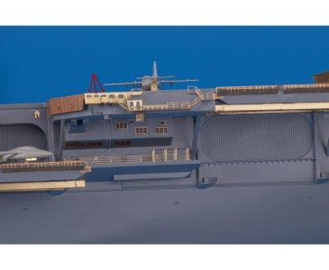
14a.jpg

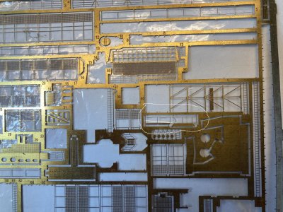
This is the Eduard photoetch for the catwalk between Elevator 1 and 2. The arrows point out the fuel station windows. Unfortunately this is the only piece in their set that represents this feature. They don’t supply the rollers either.


All the midships fuel hoses are below the flight deck in the 03 level If you don’t know what you are looking for you will miss them entirely. They can be spotted by the rollers on the coaming and directly below the roller there will be a horizontal oval opening. In the photos it appears black. The Eduard Part 5 set provides a photoetched part that represents some of these but only in the catwalk between Elevator 1 and 2. Another giveaway in these locations is a landing with two doors. One door is access to the fuel station and the other leads to the interior of the ship.
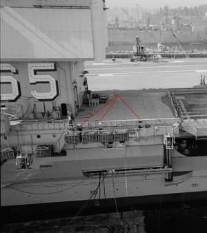
65 CVAN 09 24 1968 YARDS a.jpg

These are the fuel stations forward of the island. The red arrows point to the fuel stations. Note the double rollers on these stations because of the high coaming. Where the fuel reels are right in the catwalk there is only one.
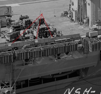
65 CVAN  ISLAND 09 24 1968a.jpg

These are the stations aft of the island. There are holes in the coaming but I did not try to duplicate this.


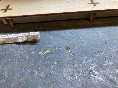
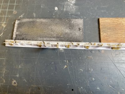
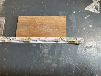
Making the rollers was fairly easy. I cut equal sized pieces of rod and glued them in place. I needed to represent 6 oval windows in the catwalks between Elevator 2 and 3. To model the oval I decided to make oval rings from plastic tube and just paint the ovals in. The plastic tube just crumpled when I tried to flatten it. I tried something more durable and used some 3/32” K&L brass tube. I first drilled out a section about 1 ½ inches long to thin out the inner diameter. I cult fine slices off it by chucking it in a drill and cutting slices off with a sharp Xacto knife as the drill spun the tube. They were too thick so I sanded them between 2 pieces of 220 grit sandpaper glued to wood shims until they were wafer thin. I slipped each ring over a tapered piece of .030” X .060” strip. By forcing them down the strip they take on the flat oval shape which I finished by squeezing them with pliers. These were then located in the catwalks and glued down.
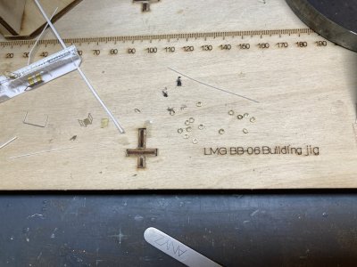
Sponson 5 (103).JPG

I have cut many more rings than I need because I will need them in other portions of the catwalks. It still seems odd that I did not lose any.
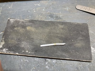
Sponson 5 (104).JPG

These are the rings on the tapered jig you can see how much thinner they are now.


This is the end of part 3.
 
Part 19 Sponson 4, 3 and 5 Part 4 of 4 parts

I added wiring, lamps, boxes and other greeblies to the inner catwalk bulkheads to detail them up. There is an aircraft power cable in the forward and aft catwalks. In the 1968 photo they show a cord on a hanger like the cords in the hanger bay. Some locations around the deck still had these but by 1978 I believe these many were replaced by the box type similar to the in flight deck stations but much smaller maybe a foot square. There was a hollow shaft that led to the 03 level. These had a weathertight door on top you reached in and pulled the cable out. There was a roller fairlead that made it easy to haul out, return and to keep the cable from falling through.

Sponson 5 (112).JPG

I’m pretty sure the hand wheel visible in this photo was used to raise and lower the barricade. There was another on the port side.


To make the power stations I cut sections of .040” square strip to come even with the top of the coaming. A thin piece of strip represents the door on top. In the 1968 photo of the aft section of catwalk you can see a large hand wheel between the 2 ladder wells. I don’t know this for a fact but I believe that this was the manual control to raise and lower the barricade stanchion on the starboard flight deck. I found a photo of the port catwalk that shows another hand wheel on that side.

Sponson 5 (105).JPG

I have added the rings and rollers for the fuel stations. The 2 A/C 400hz power stations are also added at the ends of the catwalks.


There is a saltwater fire station in the aft section of this catwalk. In 1978 All the fire hoses on the flight deck were flaked into boxes mounted to the deck or onto the coaming whether they were saltwater or AFFF. (There is a standard saltwater firehose station on the crane platform). This catwalk station was mounted on the coaming. You just need some appropriate strip with a photoetch hatch cover for a lid to make these. Under the box I placed a hose connection. The flight deck and hanger deck AFFF hose reels would come after the refit. I don’t know if they ever changed the saltwater hose stations. There were some AFFF hose reels on the island in 1978 but those are the only reels that I know of.

Sponson 5 (114).JPG

The hose box is glued to the coaming and the fire plug is below it.


With all the detail work in the catwalks done I added the outer splinter shields/hand rails. The shields should have foot and handhold to service the rafts but I did not try to make these. I first went to the Eduard parts for this set of catwalks. They furnish full rails/shields but I cut away all the solid shield parts opting to just use the handrails. I wanted all splinter shields to look consistent. I couldn’t glue the shield on the lower catwalk yet or I wouldn’t be able to do the detail painting later. I did assemble a shield which included the shields on the ladders from the upper catwalks. The bottom of this ladder well also had a splinter shield on it. I made these from strip stock and I added a small piece of shield at the top and bottom of each ladder to fence them in.

Sponson 5 (135).JPG

Here I have added splinter shield that will go under each ladder to the ATO. This photo helped me notice the missing outboard net on the MK-115 platform. I found the net on the work stand almost right below it and glued it back on.


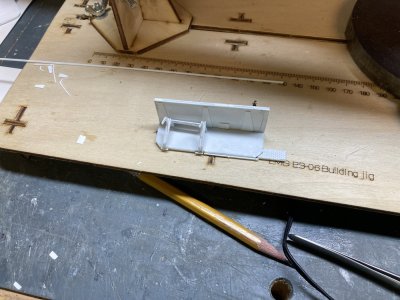
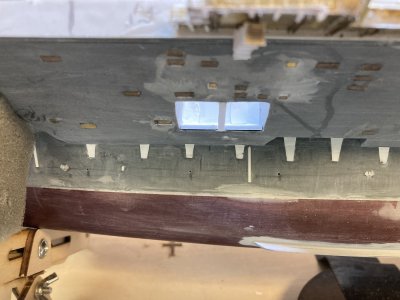
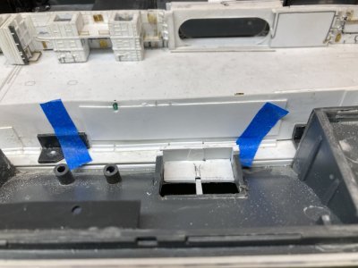
Later I can add the ladders and then glue the outer splinter shield in position. I taped the catwalk assembly back in its final location. With it secured I drilled an additional locating hole at each end just under the catwalk. I put a small section of .030 rod through each hole and glued them to the underside of the catwalk. This ensured that I didn’t glue the catwalk to the hull yet. I can remove the staples now and place the catwalk back in it location when I need to.

Sponson 5 (111).JPG

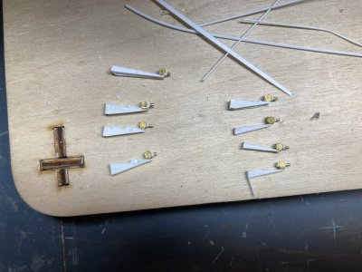
The basic long mounts are on the left along with the angled mount for the point. The two level mounts to span the fuel stations are on the right.

Sponson 5 (113).JPG

The starboard bow catwalk is here upside down. The tubs for the fuel station are installed. The step inboard from the outer edge had to be compensated for which required a two level platform. I built this part up to this point to get the stepped mounts correct.


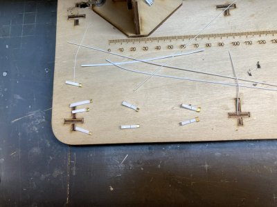
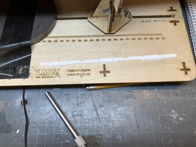
I needed to revisit the whip antenna mounts. On this section the catwalk is wider at the aft end. A caged whip mount is located there. All told I will need 8 wider whip mounts. I decided to just do them all now. There are 3 mounts that are the same as the ones I previously made but they need to be longer. There is one mount that comes out under the catwalk running along the point on the starboard side. It has the inner end cut at an angle and the two gussets are different lengths. There are 4 mounts on the bow that fit under the fuel stations these required a 2 level platform with corresponding braces. Other than these differences the mounts were built up using the same basic steps as the short ones.

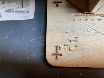
Once all the mounts were made I stowed everything but the 3 I needed now safely away. I needed each of these to have the caged catwalk underneath. I built them up the same as the one I made on the port side. When they were all assembled I glued each to its position under the catwalk. I placed a hatch on the mount above the vertical ladders. I found some railing that would serve nicely on these to serve as safety rails. I cut one section for each side of the 3 mounts and glued them all in place. I used some of the fuel cable reels from the Eduard sheet for the rotating handles which should mean that I will have enough of the regular handles to do the rest of the mounts.

Sponson 5 (115).JPG

Progressing toward the end, now all the sockets and the inner insulators have been installed.

Sponson 5 (116).JPG

I am working on the caged platforms now.

Sponson 5 (117).JPG

All the remaining mounts in the storage box.

Sponson 5 (118).JPG

The catwalk section with the whip mounts installed.


I assembled all the life raft baskets for this area and I installed all of them but the 3 destined for the lower catwalk. Eyes were added to the catwalk deck for each life raft position. I’m not sure how I will rig all these baskets but the eyes will be in position. I placed the whip mount for lower catwalk near the forward ladder which is where I drew it. This obviously was moved because in the 1978 photo it is where I put it.

Sponson 5 (139).JPG

I am assembling life raft baskets.

Sponson 5 (138).JPG

The bomb skids.


There is a bomb ramp or skid on the upper aft catwalk. This was a removable ramp that spanned the catwalk. These were only set in place if we were flying live ordnance otherwise they were stowed in the catwalk. On the outer catwalk rail there was a second ramp which kept a piece of ordnance from getting hung up in the catwalk railing. Eduard furnishes 4 ramps in their set Part 4 but they are designed for the elevators and are too short for the catwalks. I needed 6 skids for this time frame. I made mine from Plastruct channel. The piece across the catwalk has an opening that is funnel shaped to guide a weapon into the chute. This was made from a few pieces of strip. I made 7 just in case and glued one to the catwalk.

Sponson 5 (140).JPG

The life raft baskets and rigging eyes are all in place now.

Sponson 5 (145).JPG

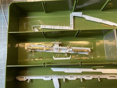
Everything has been safely stowed away.

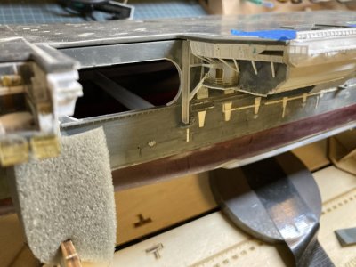
Sponson 5 (38).JPG

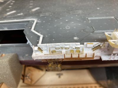
After some real sweat I have the railing around this platform and the folding crane has been fabricated and installed.


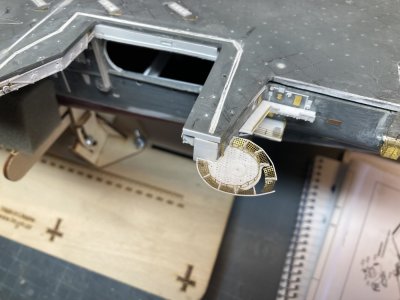
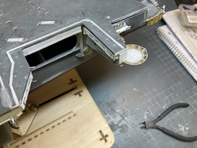
I returned to the little Calibration Lab Platform above Elevator 3. I fabricated the folding crane from some 1/16” I beam and glued it above the double doors. The last thing I needed to do was the railing. This needs multiple bends and would be difficult to get right in that tight position under the overhang. I took a small square of paper and held it under the platform while tracing the outline with a pencil from above. I used this to fold some generic railing with closely spaced posts. It worked very well but it gets really hot in my shop this time of year so I had my window A/C, a ceiling fan and a large swamp cooler going. This can generally keep the temperature in the high 70’s to low 80’s but when you turn them off the heat instantly soars.
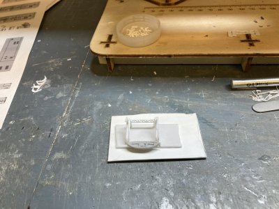
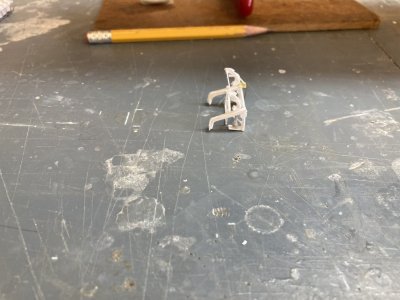
I dropped the first and second railings that I folded attempting to position them and they were blown somewhere into infinity and beyond because of all the moving air. Sweeping the floor and a flashlight search proved fruitless. I made a third railing and shut off the A/C and the cooler. With sweat running down my face and into my eyes I was finally able to get the railing installed. At noon when this happened it was already over 101 degrees outside. Today’s high was 108° Fahrenheit (42.2° Celsius). Happily temps have been fairly mild this year till now. I generally try to start work as early as possible and quit by 1:00 PM to avoid the worst heat. Getting the railing in place was a major victory and the end of further modeling today (August 3, 2026). I closed down the garage and went in for a cool drink and some good A/C.

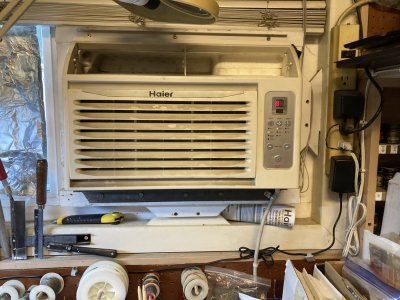
Sponson 5 (60).JPG

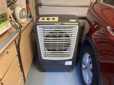
This is the air conditioner. I got it years ago when the house system broke down in the summer. We could sleep in comfort with this. After the home unit was replaced I really didn’t need the window unit for anything so I migrated it to the garage.

Sponson 5 (61).JPG

This is the swamp cooler. We all have to work around something to build models. My cross to bear is the summer heat.


Here is a brief explanation for those of you who have no idea what a swamp cooler is (the actual name is evaporative cooler). I had never heard of or saw such a thing till I was stationed here in central California back in 1975. I was born and raised in Ohio which spends most of the summer fairly temperate but when the temperature goes up there you get higher humidity. A swamp cooler wouldn’t do much there.

Essentially you put a big fan in a box, draw outside air in from 3 sides and blow out on the other. The bottom of the box is filled with water, the cooler the better, and it is pumped to the top of the openings allowing it to run down through filters which will get wet and stay that way as long as you have water in the bottom. The air will be cooled by the water in the filters coming in and blowing out.

These are very common where the climate is warm to hot and dry. It needs that dry air coming in to evaporate the water in the filters. It won’t work where the humidity is high. When the mercury tops 110° it is much less effective. I tried closing the garage and running it when I first got it but it makes the inside humid and muggy in no time at all because you keep
recycling the moist air. The hot setup is to start with the ceiling fan. As the temp climbs I crack open the garage door by a couple of inches let the cooler draw air from there. Finally when the cooler doesn’t keep pace I turn on the A/C. I survived my first summer here in an off base mobile trailer cooled only by one of these coolers (it was my first place of my own and I became very familiar with these things keeping the one on my roof running).

During all the moving around working on the model I had a small problem with MK-115 mount on the port side. Apparently I had hit it on something and didn’t notice it. It looked pretty bad to begin with but I am getting better at fixing these sorts of things. It’s just a fact of modeling that eventually you will break something while you build. Machine guns and pitot tubes on aircraft are one of my nemeses.

Sponson 5 (29).JPG

I don’t even know when this happened.

Sponson 5 (32).JPG

Unless you know that it was broke you can’t tell thank goodness.


That finishes this part. In the next I will work on the Port Boathouse (Sponson 2) and the other two deck houses (Cleat Decks by the assembly manuals. I don’t believe that was the actual name. I never heard them called that). It may be some time before I post again as I have some family things that need doing. I will work when I can and see you again in my next post. Happy modeling.
 
Mini Hobby 80502 1/350 Scale USS Enterprise CVN-65 Early

Part 20 Sponson 2 and the Port Deckhouses Part 1 of 3 parts


Ship's Boats 02.jpg

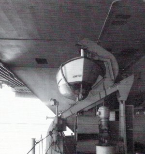
This is the view I’d see as I peeked out on the sponson. Note the overhead and the fact that there aren’t any platforms. This is the configuration of this sponson from launch until the 2 RHIB’s replaced the motor whaleboat.


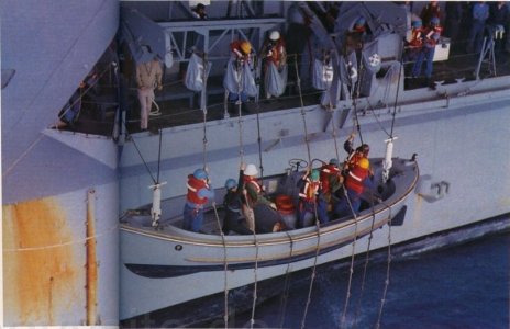
Sponson 2 or the Port Boat House isn’t somewhere that I was allowed to just go and hang out. The Bosuns Mates who were tasked with taking care of this area were pretty territorial. However they often left the doors to the hanger/ladder well and to the sponson open so I got a peek out there every once in a while. This was the home of the only duty lifeboat. It was evident from what I could see that the boat was maintained with pride. Like the Captains Gig or the Admirals Barge it was cleaned and polished to a T. The man ropes (monkey lines) were coiled into bags that had the hull number and a bosuns rating device sewed on them. If there was a man overboard or a plane went in the water the duty lifeboat was immediately manned and prepared for launch.

Ship's Boats 05.jpg

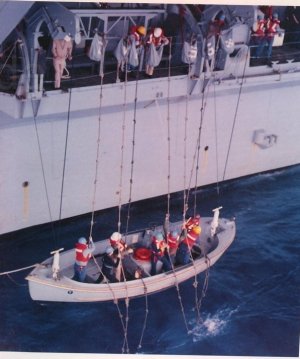
Launching Enterprise’s duty lifeboat, note how the outside feet of the rails are attached on extensions. Each man of the crew holds a Monkey Line in case the boat falls. The monkey Lines (or Man Ropes) are coiled in the 7 bags. Each bag is labeled individually (”C, V, N, an unlabeled bag for a dash, 6, 5 and the Bosuns Mate rating device.”)

Sponson 033.jpg

Here the boat has almost reached the water.

Sponson 050.jpg

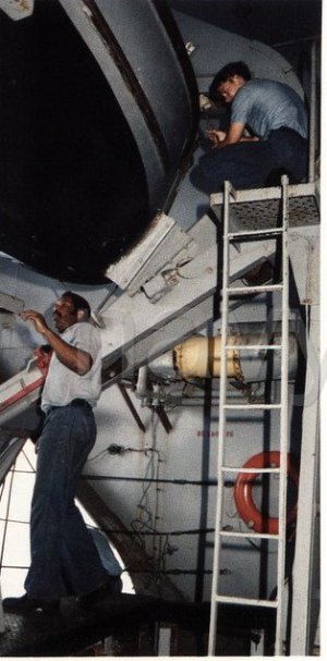
The bosuns assigned to the ships boats lavished a lot of care on their boats. On the bulkhead in the background there is the lowest row of the filters or the distribution system. I will paint the life rings and fire extinguishers separately and then install them. Note the ladder and the small platform.


This sponson was pretty large and tall for that matter. It went up from the main deck two more levels to accommodate the davits that launched the boat. They were a single bank, double arm, trackway, gravity davit (I believe that is the correct nomenclature). They could launch the boat via gravity and the arms were returned with a vertical electric motor (the vertical motor probably could also drive the boat to the launch position). I found some CAD pictures of similar davits on the USS Oklahoma City CL-91/CLG-5 /CG-5. They don’t have the drive motor they use a winch and sheaves so they aren’t the same as the unit on the Enterprise but they give a clearer picture of the way they look.

Here is a link (https://www.okieboat.com/CAD miscellaneous.html). All the davits and the motor whaleboat went away eventually and were replaced by 2 Rigid Hull Inflatable Boats (RHIB’s) and a crane. When that change occurred it appears that a small deck office or storage space was added to the aft corner of the sponson. This didn’t happen until after the turn of the century though. In 1978 there appears to be a horizontal tank there which might be a fuel tank for the boat.

cvn65nn6.jpg

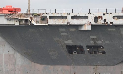
These photos from the scrapping of the ship are some of the best for detail in specific areas. The RHIB’s are gone but the crane is still there and there appears to be a shack or storage area on the aft end. Note the wiring, vents and plumbing.

Hull 124a.jpg

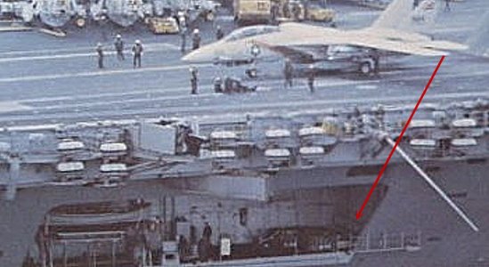
Most of my photos for the spaces I am modeling are kind of fuzzy like this. I believe that there is a tank on the aft end of the sponson, red arrow.


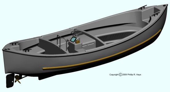
The Mk-10 26 foot Motor Whaleboat was very similar to the wooden Mk-2 26 foot Motor Whaleboat of WWII and it was the work boat of the fleet for many years. The newer ones had fiberglass hulls with a wheel and shift lever on a control podium on the starboard midships instead of a tiller at the aft end. The rudder was much smaller and did not extend up the stern. The Enterprise’s boat was grey like most everything on the ship, the water line was painted black and there was some varnished wood work in the way of rub rails. There was some bright work and fancy work (fancy work is thin rope or cord line wrapped around railings and such in a decorative way. It does provide a better grip and it is often painted white).

Mk-10 26 Ft MWB.jpg

This drawing is about as clear as it gets for the motor whaleboat. By the way there are dozens listed for sale on the internet if you want to buy one. Note how the hull extends over the rudder. I did not fix this on the Black Cat MWB.


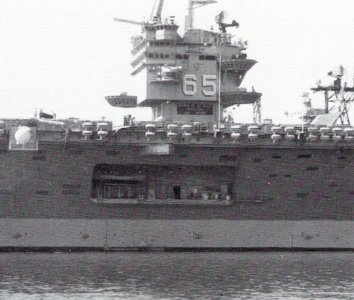
There isn’t much photographic documentation on this side of the ship at all so I went through all of my files and printed off what I could. Unfortunately the quality isn’t that good for most of them. The boat and its davits were located on the forward end of the sponson. There was a double WTD just aft of the boat. There are a number of vents and pipes on the inside bulkhead while the forward bulkhead has some sort of filtration or distribution network and the aft has that tank with the bulkhead having some wiring and panels. For the most part the details of the sponson are based on the clearer photos of the early 80’s Enterprise, the ship being stripped from 2025 or so and my drawings.

Hull 118.jpg

Sponson 2 in the early 80’s.

cvn65nn39a.jpg

This image of Deckhouse 1 is pretty clear and shows the dividing bulkhead with the large rectangular opening.

Hull 112.jpg

This is one of the few photos that shows anything about Deckhouse 1

Hull 120.jpg

And this is Deckhouse 2. The Fairleads of the 2 deckhouses are not in the same locations.


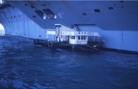
As little as I know about Sponson 2 there is even less to go on for the forward and aft deckhouses. I believe the forward provided access to the accommodation ladder (when I was on the Kitty Hawk CV-63 they had a similar arrangement and there was access to an accommodation ladder). The Admirals Barge, the Captains Gig and The senior officer’s liberty boats loaded and unloaded their passengers there. These two locations were sometimes used to tie off camels and barges when we were at anchor or moored. I have a photo of a ferry barge tied to the port side in Hong Kong. I was finally able to answer one question about what the dividing bulkhead of the two deckhouses actually looked like after finding a decent photo of the area from 2025. Originally I thought it was a solid wall inside to outside with a single oval doorway like in my drawings but the photo shows a larger rectangular opening.

65 CVAN PORT SIDE BELOW ANGLE 1975.jpg

The ferry barge tied to the port side of the ship. Note the accommodation ladder.

Sponson 2 and Port Deckhouses (1).JPG

These 6 parts make up the bulk of Sponson 2 and the 2 deckhouses.

Sponson 2 and Port Deckhouses (3).JPG

These are the Sponson 2 parts up close.


One of the first things I did was look at the kit parts for the two deckhouses and the sponson. There isn’t much to them. I haven’t found any evidence of a platform on this sponson but there is a kit part and an Eduard part to replace it. Both are just a figment of somebodies imagination. I had already cut away all the molded overheads and inboard bulkheads for these spaces and now I would be rebuilding them. The part for the sponson had to be skinned like the decks on the other sponsons so first all the detail was removed and the deck was covered with .010” plastic. I checked the fit and how far the sponson protruded out of the opening. I kept adjusting till the sponson deck was level with the hanger deck and butted up to it.

I needed the deck to stick out enough for the extension to be added (the kit part has a molded extension but it is the same thickness as the rest of the deck so I cut it off (Eduard’s instructions have you cut it off too). I had to shim the inboard edge of the deck with some strip to get it to match up with the hanger deck. Looking at photos it became apparent that the kit part was missing an important feature. The Sponson 2 deck should be cut at an angle after it passes beyond the opening at both ends. I drew a line on the forward corner and copied that for the aft. I cut off both corners and sanded everything smooth. I skinned the forward edge but the aft would be covered by the extension.

Sponson 2 and Port Deckhouses (9).JPG

The old extension is gone and I have marked the cuts that I will make for the angled ends.


Once I got the fit right I got a small piece of my perforated deck and cut it to the proper length for the aft extension on the sponson. I laid this under the kit part and cut the angle for the aft end. I marked the aft end of the kit part where the deck meets the angle of the hull to determine the inboard edge of the extension and its width. I added some webbing below and some heavier strip around the edge of the extension for strength. I placed the extension and the sponson face down on my mat, put them together and glued them with Tamiya Extra Thin Cement. I skinned the sloped underside and the entire outboard edge of the sponson.

Sponson 2 and Port Deckhouses (17).JPG

The angled cuts have been made and the extension has been added.


The Eduard Part 5 piece for the sponson extension is attached to the railing for the sponson but the railing wasn’t made to allow for davits protruding through it or for the angle at the forward end. I was going to use just the deck but then the extension would have been too short after cutting the angle. Those parts went into my scrap box. I let it firm up and did a final test. I drilled a couple of holes through the deck and into the hull. Using some plastic rod I made two locating pins. This allows removal of the deck until I am ready to glue things together.

Sponson 2 and Port Deckhouses (20).JPG

The second batch of parts to make the davits.


The gravity roller track davits on Sponson 2 required two attempts to get good parts. I used the Silhouette to make them but when you are dealing with small pieces like these it can be difficult to get them right. In this case my bitmap drawing resolution got changed somehow which changed the size and made all the parts too small. (No idea what key I fat fingered to do that). I looked for 3D printed or photoetch parts for these davits first but I couldn’t find any until I stumbled on this Swordfish Website after I made mine. You will still have to make the trellis beam and some other modifications to use them for Enterprise. Here is their link https://www.swordfishmodels.com/product-page/set-of-gravity-davits

Sponson 2 and Port Deckhouses (22).JPG

The basic assembly on the davits is done. The glued up subassembly is still on the double sided mounting tape.


It would have been nice if the Eduard Enterprise set included these davits instead of a spurious platform. I cut the pieces out of.010” sheet then built the parts up from multiple layers. There is a trellis beam supported on two pylons that face outboard instead mounting them to the inner bulkhead. When this was assembled it was placed vertically on some double sided foam mounting tape. Each track required 2 outer panels, 2 inner tracks, 2 outer reinforcement ribs and several spacers. The parts were built up and glued one side at a time to the support trellis ensuring they stayed perpendicular to it. I checked the part against a Black Cat WWII 26 foot motor whaleboat periodically as assembly went along.

This is the end of the first part of this post
 
Part 20 Sponson 2 and the Port Deckhouses Part 2 of 3 parts

Sponson 2 and Port Deckhouses (26).JPG

The angles that the outer feet of the davit sit on have been added along with the gussets. The inboard bulkhead is in position and the upper portion of the hull stiffener plates is installed. I have also installed the boat boom.


The kit doesn’t have one of these whaleboats. The instructions have you hang a Captains Gig type launch from the overhead of the sponson. The Black Cat whaleboat will have to be modified to modernize it. The stern of the Black Cat WWII Mk-2 model is different than the Mk-10. The stern of the hull should extend over the rudder but I chose not to mess with fixing this and just cut the rudder down. I made a control podium, glued it in position and topped it with a tiny wheel. The arms took two layers glued together and then glued in the upper position on each track. I added some gusset detail to the rails and the keel block and steadying arm to each davit. This type davit has a long keel rest bar which folds down and away when the boat starts to move down the rails. I copied the supports that I saw in a photo and got the look if nothing else.

Sponson 2 and Port Deckhouses (62a).JPG

The davits are just about complete in this photo.


There is an access platform with a vertical ladder at the forward support pylon which I made from generic photoetch parts. A drive motor and a boat winch for the falls were added from parts I had already made up and spare winch parts. I added some details to the davits and the forward set of rails. I made up a pair of sheaves for the boat falls and drilled some holes in the bow and stern of the boat. Some .010” rod was glued into each hole. I cut 2 small pieces of Albion Alloy brass tube and slid them over the plastic rod. I added some small pieces of rod above the brass in a T shape to make the attachment devices that hooked the boat to the falls. When these were cut short enough to reach the sheaves they held the boat in position on the davits. I did not plan it that way just a happy accident.

Sponson 2 and Port Deckhouses (27).JPG

Sponson 2’s basic assembly is clearer in this photo without the davits.


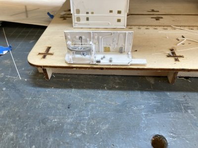
The next step was to add an inboard bulkhead at the same position as the hull. I cut and fitted some .040 inch sheet, got an acceptable fit and glued it to the inboard edge of the deck. Then I added some hull reinforcement stiffener plates cut to match up with those visible below the sponson. There were 3 on the inboard wall. I put a couple pieces of angle for the davit to rest on at the outer edge of the deck. Later I added 2 gussets under each angle after reviewing some photos. I placed two pins on the base of the rail legs on the outboard end and drilled locater holes for them. Once the davit was located I made a double WTD and glued it in place (I wasn’t satisfied with this so later I re did it with some brass parts. Aft of the davit I glued the boat boom to the edge of the sponson. There were a couple of lockers from Black Cat, a kit fairlead, an Eduard bitt, the tank and the winch for the falls to add detail to the deck.

Sponson 2 and Port Deckhouses (36).JPG

The overhead is set in pace on top of the bulkheads.

Sponson 2 and Port Deckhouses (46).JPG

The overhead from below.

Sponson 2 and Port Deckhouses (59).JPG

Almost all the detail is now on sponson 2. Behind it is the detailed overhead. I didn’t care for the original set of doors that I made and they were replaced in this photo.


I went through the usual steps for vent ducts, electrical and plumbing on the inboard bulkhead based on what I could identify in my two reference photos. Jacques at Ship Models Forum did really nice work on this area with the 2 RHIB’s here is a link to his model. www.shipmodels.info/mws_forum/viewtopic.php?f=59&t=210966

I made some plumbing for the distribution thingy on the forward bulkhead and then some wiring and grills and panels on the aft bulkhead. The overhead of Sponson 2 is made up of plates like the hull. There are no visible support beams. There is some plumbing and some vent grills. Once the inboard wall was dry I cut a piece of .020” sheet to size so it just rests on the bulkheads and the outer hull. I cut and glued pieces of angle to hold the part in place. I used various grills from my photoetch stash. The plumbing is plastic rod. It’s an approximation and not 100% accurate but the look is there. With this done all that was left was to finish detailing the inner bulkheads. To light this area I will use LED’s as there will be no way to hide light holes.
Sponson 2 and Port Deckhouses (60).JPG


This is the plumbing system on the forward bulkhead.

Sponson 2 and Port Deckhouses (70).JPG

The completed Sponson.

Sponson 2 and Port Deckhouses (78).JPG

The completed boat.

Sponson 2 and Port Deckhouses (82).JPG

The final addition to Sponson 2 was a vent grill on the aft bulkhead. I had to be careful what I added and where I put it here because more would not have allowed me to insert the assembly in the opening.


The decks for the 2 deckhouses (4 parts total) were too narrow and I had removed the rib separating the two ports at each deckhouse because they were so thick with the end result being that the kit parts weren’t usable. The kit deck should end at the hull (despite what I said in an earlier post). I cut my own deck from some scrap plastic so it would be one piece. I went through the same process to fit these as I did for the sponson. I even added a locating pin in each one.

Sponson 2 and Port Deckhouses (31).JPG

The forward deckhouse seen from outside. I have glued the separators to the hull at this point but later I attached them to the deck assembly. I haven’t placed the additional strip to the front edge to fair it to the hull.

Sponson 2 and Port Deckhouses (30).JPG

The aft deckhouse under construction.


I added the inboard bulkheads by cutting and fitting them behind the fore and aft sides at the same position as the hull. There is a substantial gap between this bulkhead and the molded bulkheads of the kit. I filled the gap with .080” strip (the plastic of the deckhouse walls was really that thick. I detailed the inner bulkhead with the hull reinforcing strips like I did on the Sponson. I spent a good bit of time getting the separating bulkhead fitted. I used .020” plastic to make it which gives it a more scale appearance. The large rectangular opening was first scribed with a Trimaster template and then cut out. After the part for the forward deckhouse was made I checked it in the aft deckhouse and finding the fit good, I copied it. I glued a piece of .010” X .040” strip in the opening of each separating bulkhead to form a coaming.

The strip separating the 2 ports was simply a piece of .060” strip beveled at both ends so it fits flush in the opening. I had to cut a notch in the decks so they fit around the separator. Later I found that it worked better for me to remove the separator from the openings and glue it to the deck assembly in the notch. It makes for a more solid assembly. To blend the decks a final piece of strip was added to the outboard edges so that it extended past the hull. I sanded a bevel on these to match the slope on the hull. The fit is tight and positive.

Sponson 2 and Port Deckhouses (39).JPG

The forward Deckhouse with the separator installed on the deck. I have cut out the rectangular opening and fitted the bulkhead to the deck and the separator strip.
Note the thickness of the white spacer.

Sponson 051.jpg

The overhead of Deckhouse 1 has open support beams so I assumed that Deckhouse 2 did also.

Sponson 2 and Port Deckhouses (43).JPG

The overhead for Deckhouse 1.

Sponson 2 and Port Deckhouses (45).JPG

The overhead in position, the backlighting highlights the support beams. I have the opening faired into the hull.


Constructing the overheads for the 2 deckhouses wasn’t much different than the overhead on the sponson. I found a single photo that shows part of the overhead of Deckhouse 1 and there are support girders for it. I assumed it would be the same in Deckhouse 2. I marked the locations of the 3 bulkheads on the overhead and then added the girders like I did under the flight deck. I went a step further and imagined some plumbing. To light this area I cut holes in the overhead for the hanger LED’s to filter down. I added a photoetched accommodation ladder to the well just aft of the deckhouse.

Sponson 2 and Port Deckhouses (52).JPG

There wasn’t enough space to add the kit ladder and glue the photoetch part to it like I did at sponson 5.


This is the end of the second part.
 
Part 20 Sponson 2 and the Port Deckhouses Part 3 of 3 parts

Sponson 2 and Port Deckhouses (71).JPG

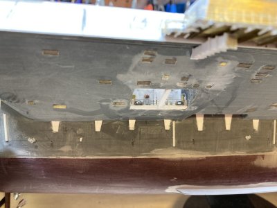
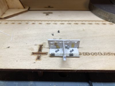
The 2 Deckhouse assemblies under construction.

Sponson 2 and Port Deckhouses (72).JPG

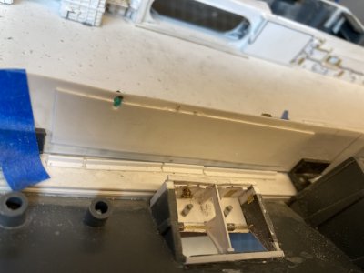
Deckhouse 1 getting mated up to the hull. I added the door to the accommodation ladder.

Sponson 2 and Port Deckhouses (79).JPG

Looking forward at Deckhouse 1.

Sponson 2 and Port Deckhouses (80).JPG

Looking aft at Deckhouse 1.

Sponson 2 and Port Deckhouses (81).JPG

Deckhouse 1 in place.


About the only item that I could discern from the photos of the deckhouses on the bulkheads were 3 electrical panels on the aft end of Deckhouse 1. The rest of the bulkhead detail was pure guesswork and imagination. I added wiring, 1MC loudspeakers, lights, some plumbing, lamps, lockers and fire stations. The fit of the assemblies was pretty tight but I was able to add an access door to the accommodation ladder and some vent grills to the fore and aft bulkheads. On the deck there was a fairlead in each opening, (pay attention to the photos though because they are not in the same positions at both deckhouses). I placed bitts inboard of the fairleads then added railing to finish the deckhouses off. Then I grit my teeth and carefully popped the 3 assemblies in position. Yay no damage.

Sponson 2 and Port Deckhouses (83).JPG

Deckhouse 2 out of the hull.

Sponson 2 and Port Deckhouses (84).JPG

Looking aft at Deckhouse 2.

Sponson 2 and Port Deckhouses (87).JPG

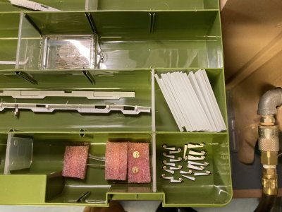
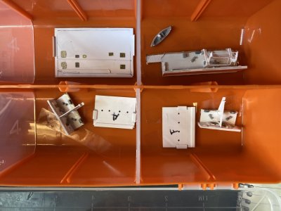
More fragile parts in boxes.


I packed all the delicate parts away in a storage box for safe keeping. Because this essentially finishes this section off I am going ahead and posting it. I have done some more work on the port midships catwalks but none of that will be posted until my family vacation is finished. When I post again I will deal with those catwalks then move back to starboard and complete the area around Sponson 1. Till then enjoy your modeling.
 
Back
Top