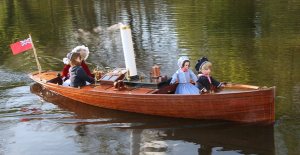
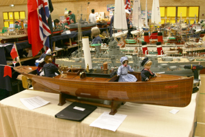
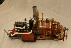
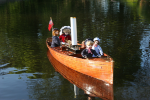
Natterer - A Lake Windermere (England) Steam Launch

Joined
Mar 17, 2018
Messages
559
Points
353

Location
UK
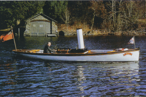
A log of the build of an 1800mm (6 feet) steam launch

‘Natterer’ – A shipbuilding Odyssey?

In 1977 I set out to build a steam launch. In 2010 I finally finished it.

So what had I accomplished in the intervening 33 years? Well, quite a lot – I learnt how to machine metal; how to draught a boat’s lines; how to build a wooden hull; how to install a steam plant and fairly simple electronics; and how to stop bleeding and apply sticking plasters.

I had written a partial write-up many years ago, to put in my club newsletter (circulation at least ten people – a very small club, but beautifully formed), so I’ve used this as the starting point, and added further sections and photos to suit.

Hope you like it! I’ll post a couple of photos now, then add more text as we go along
97370

97371

97372


‘Natterer’ – A shipbuilding Odyssey?

Ann, the better third, made a serious error of judgement in 1977 to compound the one she had made in 1974 when she married me. Despite all the warning signals that she had seen in three years of marriage, she failed to recognise she had a fanatical modeller on her hands, and asked me what I wanted for Christmas.

Well this was too good an opportunity to miss, and it germinated the seed of an idea I had been toying with for years- I wanted to build a steam launch! So she gulped, looked at our finances, and bought me a Unimat SL lathe.

As luck would have it, that year we had a holiday in the Cotswolds, and wouldn’t Henley-on-Thames be a nice place to visit, and look! - there might be an interesting shop over there, down that little alley we can’t quite see from here, but if we go over the road……?

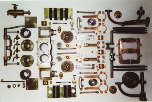
Yes, Stuart Turner Ltd still had their premises there in 1977, before they decamped for the Channel Isles, and before the day was out I was the proud possessor of a set of castings for a Stuart Launch engine, and Ann was £19.80 lighter in pocket with a suspicion she had been out-manoeuvred. (Incidentally, that same set of castings would now cost £282 !)

Now the brighter ones amongst you will have twigged that there appears to be an element of cart before horse here, as no mention has been made of a boat to put said engine in. That’s right, Ted had got it xxxx about face, and hadn’t got a clue as to what sort or size of boat he would eventually build!

That didn’t matter really, as I considered that the heart of the project was the engine, and that a suitable hull would crop up eventually.

So off to the engine, and the realisation that I was going to have to learn a lot of new techniques in order to machine a relatively large engine on a lathe that was basically tiny. First rule of learning - start on a simple part, where it wouldn’t matter if I ruined it - so what do I start with? - That’s right - The cylinder block!

No, I’m pleased to say I didn’t ruin it, but the lathe was very hard pressed to accept such a block of cast iron, and I had to resort to machining surfaces true, but to nominal dimensions, and make matching parts to suit.

It soon became apparent, as my skills improved, that there was no way I was going to be able to mount the cylinder block on the lathe in order to machine the cylinder bores (two of them, each 1” bore and stroke) as there just wasn’t enough swing over the bedplate, and I didn’t have a boring bar.

Fortunately, my neighbour was a shop floor manager with a machine company manufacturing high speed looms, and he came to the rescue.
‘What tolerance do you want it bored to, Ted’
-‘Er, it doesn’t really matter, Robbie, as I’ll just turn the pistons to suit’
The silence that ensued spoke volumes as 30 years of machining experience looked down his nose at the unpleasant smell of 30 days bodging.
‘I’ll give it to one of my apprentices then, as a training exercise’

Three days later, the cylinder block returned, with the pointed observation that it had been turned to 1”, with a tolerance of + .0001” – that’s right – a tenth of a thou! I took him at his word.

After this, machining proceeded briskly, with bedplate, journals, columns fairly flowing off the lathe.
I learnt how to drill and tap; what to do when the tap broke in the hole (Throw away and start again - luckily it was a small part!) and I even learnt how to silver solder and put out the ensuing conflagration.

But all this time, I was aware that the real test of my new found skills was fast looming on the horizon - the crankshaft.

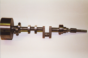
The crankshaft was a single casting, with two cranks at 90 degrees. It would just fit on the lathe, and I was able to machine the three main bearings with no real problems. The fun began with the machining of the offset cranks. Luckily, I had picked up a book in my travels which suggested the solution, and I obtained a 2” length of 2” diameter brass round, into which I drilled an offset hole the diameter of the crank. The hole was drilled offset by the throw of the crank, and two short dowels were set into the end of the round. This enabled me to clamp the end of the crank into the round, secured by two grubscrews, with the dowels securely locating the crank web such that the crank journal (The big-end) was now firmly held on the centreline of the lathe. Bingo! - the big ends could now be turned!

After that little triumph, mere bagatelles such as double eccentrics and Stephenson reversing links held no fears for me, and the engine rapidly came together. It even looked vaguely like the picture on the box! The engine was assembled with the exception of the connecting rods and pistons, when fate dealt a hand, and we decided the time had come to move house.

The new house was 120 years old and looked it - major work was required. The engine was wrapped up and put away for the duration - it was to be seven long years before the project once again surfaced.
97373

97374


‘Natterer’ – A shipbuilding Odyssey? – Part 2

‘Why do we need to move? What’s wrong with this house? We can’t afford it! Give me one good reason why we should move! - (Series of dull thuds, reminiscent of heavy objects meeting flesh) - Alright, we’ll move, but please stop!’

We found a house, with an acre of ground (Vehicle storage said Ted, Goats said Ann), and a proper walk-in room in the roof (Bedroom said Ann, Workshop said Ted). The goats duly arrived, but the amount of work required on the house meant the workshop/bedroom remained as a store-room, and no modelling took place for seven long years.

During this time however, we discovered that Mecca for steam boat enthusiasts, namely the Windermere Steamboat Museum. What a feast of delights! Steamboats of all shapes and sizes wherever you looked! The graceful lines of the Victorian launches, the colours of the timbers and above all the sight and sound of operating steam engines took our breath away. We were particularly attracted to “DOLLY”, the oldest working steamboat in the world, which had spent some eighty years on a lake bed after being nipped in the ice.

I approached the museum, and was readily given permission to spend a couple of days measuring her up and taking numerous photographs. They even had a small-scale set of lines available! Once home, I set to with slide-rule and drawing board and converted those lines into a working set of drawings. This was where the problems started! You will remember that in the last episode I admitted I was doing things backside foremost, and had started with the engine! Now said engine was quite big (and heavy) and clearly wasn’t going to like being shoe-horned into a two-foot hull. In fact, when I had finished all the measuring and scaling the hull ended up at about 72 inches ( 1830 mm to the youngsters)

Alright, so it was going to be a big boat! That wasn’t a problem in itself, as I had always wanted a big hull, but the problems arose when I worked out that the model’s calculated displacement to waterline was about 5 lbs less than the all-up weight would be! Calculations also revealed that the metacentric height was going to be in the region of 3/8 of an inch, which when combined with the nearly hemispherical mid-ships section meant she was going to be rather tender and roll like a pig in mud. (or similar – substitute as you see fit)

The solution was to subtly rework the sections to give a greater displacement, with additional buoyancy being placed in the quarter buttocks, so as to increase the metacentric height, and reduce the roll rate. On paper, it would work, but the weight of the hull and engine plant would be critical, with no room for error. The only other solution would have been to increase the hull length to seven feet, but that was starting to be ridiculous!

On with the motley! – Have you ever tried to produce drawings for a 72” hull on a 40” drawing board? – Difficult. As I started to scale up the museum’s lines drawing, it became apparent that all was not well, and that the drawing was highly suspect. A good excuse for a further trip, and a days’ measuring. Back home, and I was able to translate the new information onto the drawings and fair the lines up properly. Incidentally, if you are ever having to prepare a set of drawings, remember a hull is three-dimensional, and cannot be adequately defined with just a profile and sections on a two dimensional drawing – it is essential to add both futtock and buttock lines to the drawing. The profile, sections and buttocks may appear to give a true form, but attempting to fair in the futtocks will soon highlight any discrepancies.

The final drawings were prepared at work on an eight foot table, where I coerced all the members of my drainage design team into holding down a six foot spline as I inked in the lines!

It was 1988, only eleven years after the start of this tale, and at last! I had a set of working drawings! At last I had a stock of well seasoned lime! At last I had an engine! At last I...........don’t think I like the boat any more, said Ann.
97367

97368

97369
 

Attachments

  • Natterer - Ch 1.docx
    1.4 MB · Views: 42
  • Natterer Ch 2.docx
    1.3 MB · Views: 17
Last edited by a moderator:
Not quite sure what's happening here- probably down to the original articles being written in word, with photos added.
However, if you click on the attachments it opens the file and puts it on the bottom of the screen as a document to open.
Perhaps someone who knows their way around computers can suggest a way of persuading the files to display in the post itself? - i'm still only one or two steps up from an Abacus!
Hallo Ted,
I solved the problem and copied the text and photos from the word docs into your post - so it is solved -> I am happy that you started this building log and will follow (and "solve" if necessary) with big interest
 
Hi Uwe,
Thanks for that! Is the 'fix' something I can do at my end? - otherwise you'll be doing a lot of converting!

Ted
 
Hi Ted, I found your build log a very interesting and well written. Despite all of the challenges and time spending, she is a true masterpiece considering the size of the working steam engine and the parts made off. No so many of us have the ability, nor the skill set to make something similar. Many thanks for sharing with us your fine craftsmanship. Thumbsup
 
Thanks Jim,
Your comments are greatly appreciated! Everyone has an ability to do something - I just happen to be 'good with hands' as my wife once said to a group of school friends - you can imagine the comments!

Ted
 
G'day Ted, she looks really nice, I'm looking forward to the rest of your build, I've just about finished my build of the Borkum Steam launch, but for various reasons I'm running it through an electric motor with a false boiler,

Best regards John
 
Hi John,
Many thanks for your comments! I'm going to go and have a look at your Borkum noiw!
Natterer is steam driven, but as you will read later, she has an electric drive as well (just in case) driven by a small battery. I found four 12v sealed gel batteries weighed the same as the steam plant, so they are now interchangeable, and I can run all day on electric if I wish.

Ted
 
Time for a little more on Natterer - hope you are enjoying it!

‘Natterer’ – A shipbuilding Odyssey? – Part 3


You could have heard a feather drop – ‘What do you mean you don’t like it? What’s wrong with it? You’ve fallen in love with a bat?- Oh, you mean the steam launch ‘Bat’’
I suppose I should have realised, as we are both members of Durham Bat Group (Yes, really, the little furry things that fly at night) and once she had seen this little boat with ‘Bat’ on the bows, that was it! It wasn’t really that she didn’t like ‘Dolly’; more a case of preferred ‘Bat’.
Now model steam launches are expensive to build, so the more realistic amongst you will realise that it is very necessary to keep the better half (or third in my case) fully committed to the project. That is to say, what the chancellor wants, the chancellor gets!
Actually, I have to admit I was in two minds about ‘Dolly’ in any case, as even with all the ‘modifications’ I had made to the hull lines the calculated all-up weight of the boat was still very close to the waterline displacement, and you inevitably find the weight increasing during the build. In addition, the unusual lines of ‘Dolly’, and the still relatively small metacentric height meant her stability was likely to be poor.
So I wasn’t really too worried about going back to the drawing board, and we went across again to Windermere (any excuse) to have a close look at ‘Bat’. I’d always liked the look of her, and had even bought the small scale set of lines from the museum some years before.
Close study of these, and a couple of days spent measuring up the hull confirmed that she was likely to be a far better bet in terms of stability, so a start was made on some full-size (model) drawings.
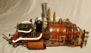
I used the same techniques as for ‘Dolly’ and again ended up with a six foot hull! That was fine, but I started to run into a few problems with regard to the boiler, as whilst ‘Dolly’ had a straightforward Scotch Marine, ‘Bat’ employed a Lune Valley paraffin-fired boiler for fast steam raising. It would have been impossible for me to duplicate this with my rudimentary boiler-making skills, so I had to set to and design a suitable vertical boiler for gas firing. The extra weight of this, and the extra height to allow all the necessary internals to be stuffed in meant that I had to increase the draught by about half an inch, but this had the advantage of giving me extra displacement and a more stable hull.
So far, so good! The small-scale set of lines weren’t too inaccurate this time, and I was soon able to push and pull them around to produce a hull shape that was reasonably in line with the original. The scale ended up at 1 to 4.5, but everything was going to have to be made by me, so it didn’t really matter.
By now we were in 1996, having started in 1977! Just too many other things to do! I had bought a huge stack of good quality lime timber sometime around the early eighties, but in 1996 I had a stroke of luck when Bryan Young, a very good friend, offered me some old mahogany flooring in strips about 80 x 20 mm by 2000 long at a nominal cost. The boat really cried out to be built in mahogany, but I will not buy new mahogany on principle, as we are doing so much damage to the rain-forests. I don’t have the same problems with re-cycled materials, provided I know the provenance.
The band-saw and the Unimat lathe, set up as a planer, reduced the majority of the timber to 20 x 3mm strips, albeit rather slowly, but with less wasted wood than having it done commercially. This was an important consideration, as I worked out there was just enough material to do the job.
So far, so good. Then in 1997 I happened to visit Bryan again. (The same friend who had supplied the timber – keep up!) ‘Have you seen the boiler for sale at Allen’s?’ (Model Shop in Whitley Bay) Visit cut short, and a quick dash for the model shop. The boiler was a Scotch Marine Dryback, Inglis modification, and the workmanship was superb. The only trouble was that it was a horizontal boiler, whilst ‘Bat’ should really have a vertical, as noted above. On the other hand, the construction of the boiler was the one part of the build that was really putting me off, and in reality was probably the reason why this project was taking so long.
Allen allowed me to take the boiler home, and an intensive evenings’ measurement and calculation ensued. The boiler’s capacity was found to be adequate, and very careful calculation showed that I could actually get it into the hull. Close inspection confirmed the workmanship as being as good as anything I had ever seen, the silver soldering being incredibly good.
The chancellor disappeared to work on the household budgets, and agreed it was an exceptional purchase at £195, when I had commercial quotes for my designed boiler in excess of £1000, and a quick pricing of the materials and all the fittings that came with it was in excess of £500. (And these were at 1997 prices!)
That did it. I bought the boiler the very next day, just ahead of three other people who were very interested.
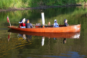
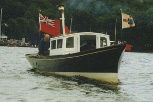
By this stage, I’d come to the conclusion that since I had modified the hull lines, changed the boiler and decided that I didn’t want to paint the hull, I could hardly claim she was a model of ‘Bat’! So we had a think, and better third (aka The Chancellor, and therefore highly involved with this boat) suggested we called her ‘Natterer’, the name of another species of bat. I rather liked the idea, particularly as it brought to mind the distinctive sound of a steam plant happily ‘nattering’ along. So ‘Natterer’ it was to be, representing a typical Victorian gentleman’s steam launch of about 1890. The steam launches on Windermere were largely owned and run by the newly wealthy Manchester industrialists, both for pleasure and to demonstrate their success. The boats created a “Golden Age” of steamboating on the lake.

98938

98939

98940


‘Natterer’ – A shipbuilding Odyssey? – Part 4

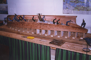
The wood for the boat was ready, so a start was made with the keel, stem, stern and deadwood. Quite an assembly in itself, as it all had to be scarfed together, and then the rabbet cut in to take the ends of the planks and the garboard strake (the one next to the keel). This boat was going to be built as full size practice! No particular problems with this bit, just a need to keep everything absolutely square otherwise the boat was going to go round in circles. The prop shaft was also built in at this stage.
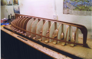
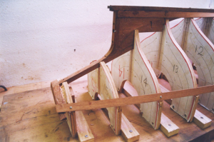
Bryan, the same friend who supplied me with the timber also gave me the building board - All seven foot of it! The centreline was scribed on it, and the positions of all the sixteen shadows (the temporary formers over which the shell would be built) marked on. The shadows themselves were cut from the old doors I’d saved when I replaced all the kitchen units two years previously (Never waste anything) These were all cut out on the bandsaw and screwed in place on the building board, before dropping the keel assembly into place on top, the hull being built upside down.
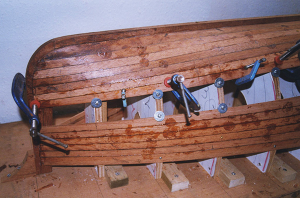
The garboard and gunwhale strakes were then trimmed and fastened in place over the shadows. These are the only constant width strakes in the boat (carvel built), and once they were in place, I could measure up the distance between these two strakes at every shadow position, divide the distance by the number of strakes I wanted to put in, and then mark and taper every strake to suit. Easy done, Eh? - Well actually no, as a boat’s hull has lots of ins and outs, and while the above may hold true for the mid-sections and the bows, it certainly wouldn’t work for the stern, where I had to use stealers next to the keel, and joggle planks together under the counter to make them all fit.
Anyway, the next job was to glue all the strakes in place, and I found that as the boat was so large, and each strake needed so much temporary clamping (fourteen G-clamps and as many screws) I couldn’t use my normal five minute epoxy, and had to resort to long set Araldite. This meant I could only fix one strake per night, and there were thirty-two of them!

98941

98942

98943

98944

98945


All for now - Chapters 5 & 6 to follow shortly.

Ted
 
Parts 5 and 6 for your delectation.

‘Natterer’ – A shipbuilding Odyssey? – Part 5


The final two planks, one on each side, had to exactly fill the remaining gap and had to be very accurately measured and profiled on both edges. Each plank took two nights to shape and fix in place, and I hadn’t any margin for error, as I was down to my last good pieces of timber. ‘Measure twice, cut once’ was the order of the day, and happily at the end of it the fit was good.

I left the hull for three days to fully dry, before attempting to invert it, and then took my courage in my hands, unscrewed all the shadows from the building board, and for the first time turned the hull upright. What a wonderful sight! The hull had looked just like an interesting curved surface when upside down, but when upright it immediately became alive, and the true beauty of the hull form could be seen, with the subtle rise of the sheer to bow and stern, and the way the turn of the bilge gradually turned in to the tuck of her stern under the counter – stop it, Ted – you’re a married man!

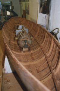
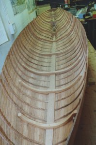
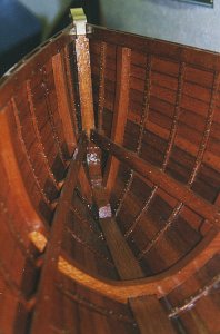
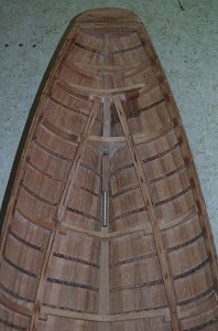
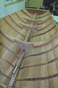
Now for the next stage, the fitting of the internal ribs. The hull had a total of 16 bent ribs down it’s length, with a further nine heavier carved frames. The ribs were continuous from gunwhale to gunwhale, except where the hull narrowed at each end, and the keelson had then to be fitted before the frames were installed. The ribs were 7 x 3mm mahogany, and were pre-bent around a piece of steel tube, heated by a gas torch. This operation proved tricky, as the difference between too little force in bending and consequent total ineffectiveness, and too much with consequent breakage was very small. I broke many pieces before I got the hang of it, and burnt my fingers several times, but eventually managed a full set.

Tap, tap tap – ‘One thousand three hundred and seven’; Tap, tap tap – ‘One thousand three hundred and eight’; Tap, tap, tap – ‘One thousand three hundred……….’ ; - You’ve guessed it; we’re at the riveting stage.

Full size construction uses copper nails which are driven through the timbers. A copper “rove” or washer is then driven down over the nail, excess nail nipped off, and the end then hammered over or ‘upset’ to ‘clench’ the nail. In full size it is a two man job, one to drive and hold the nail, and the other on the inside of the boat roving, nipping and clenching.

I used 1/16 x ½ inch copper rivets, which were pretty well to scale, but had great difficulty finding something to use as roves. Many modellers use modern 1/16” i.d. brass washers, but these tend to end up grossly overscale, and to my mind totally spoil the effect. I couldn’t find 1/16 washers in copper, and reluctantly decided I would have to use brass, but wasn’t happy about the scale effect. As luck would have it, I called in on my usual nut and bolt company when out and about, and asked if they had any small 1/16” i.d. washers. ‘Oh yes, the computer says we’ve got a packet in stock with about 1100 in’. When they eventually found them, at the back of the biggest warehouse you’ve ever seen, I was ecstatic - the washers were like nothing I’d ever seen before, and had a very small o.d. - they were exact scale! The only problem was I needed at least 1600. The company said they would get some more from the same supplier, but when they came, they were much wider. We checked, and found the original washers were stocked in 1981, to an obsolete standard, and no longer available!

This was a poser, but I decided I would use the original washers where they showed on the finished boat, and the wider ones where hidden. So first I counted the original washers to make sure I had enough for this course of action and found I had well over 2500! These things were tiny, and all of them could have fitted in a large egg-cup - the original supplier must have said ‘sod it, I’m not counting those’ and just chucked a handful in the bag to fill the warehouse’s order.

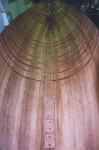
With the immediate problem solved, I started to fit the ribs. One of the midships shadows was removed, and the rib glued in place. Next, 1/16” holes were drilled through plank and rib, and the outside countered-bored to a depth of approx. 1/16” to allow the head of the rivet to sink in so it wouldn’t disappear when sanded flush. The rivet was then driven into the hole after being dipped in Araldite, before a washer was threaded over the shank on the inside, the rivet nipped off about 3/32” above the washer, and the end turned over, or ‘upset’ (Lovely word) to clench it home, using a light hammer and a heavy lump of steel as an anvil against the rivet head. I didn’t of course do each operation on each rivet one at a time, but drilled all the holes in one go, then countered-bored and so on. I found the work to be quite physically demanding, and found I could only put in a maximum of about 120 rivets in a three hour session.

I started off very tentatively, only removing one shadow at a time, and being very careful with the hammering, fully expecting all the planking joints to open, but soon found there wasn’t a problem and ended up with no shadows in place at all, as they just got in the way! The hull remained absolutely stable throughout.

1600 rivets later, all the ribs were in place, and I turned my attention to the frames.

View attachment 100488

Natterer - Old007.jpg

Natterer - Old025.jpg


‘Natterer’ – A shipbuilding Odyssey? – Part 6


The keelson was fitted next over the full length of the keel, effectively sandwiching the bent frames where they cross the keel, and preventing any subsequent movement.

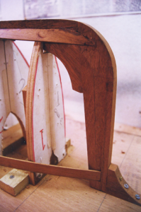
The main frames, of which there are only nine, comprised three pieces; a floor section which straddles the keelson and extends out to the turn of the bilge, and two extension pieces which overlap with the floor section and extend up to the gunwhale. They were all cut from 10 and 12mm mahogany which came from an Edwardian wardrobe originally belonging to my Gran. I can remember the wardrobe in it’s full finery, but when Gran died it was cut down and turned into a couple of chests of drawers and a mirror by my Aunt, eventually to come to Ann and myself as bedside chests when we bought our home, then finally to be overcome and dragged up to my lair. Can’t bear to see good timber going to waste, especially when it’s re-use helps to minimise further damage to the rainforests - I won’t use new rainforest timbers if I can possibly help it - you can always find old or a substitute. Enough proselytising - back to the plot!

The extension pieces, like the floor sections, were cut and shaped almost entirely by eye, using the belt sander. I have tried the job from first principles, carefully marking out by hand and trimming to lines, but it never works out as well as I hope. I find that your eye and skill with the shaper stand you in much better stead, and you get a much closer fit when you are attempting to fit a curved timber that twists within it’s length.

The extension pieces were finally all made and fitted in place, and the tops trimmed down level with the top strake.

At this point, the box of copper rivets came out again (groans all round) All the main frames had to be riveted to the hull, as well as glued! Not nearly as bad a job as the bent ribs, as the rivets didn’t project through the frames, and hence only had to be glued, and not roved and upset. Where fixings were supposed to come through the frames, I just used another rivet and washer on the inside! What did surprise me however, was the sheer number of rivets still required to finish the hull! I had reckoned on about 2000, but in the event, after adding in all the plank ends, the overlaps, the whales, the doublers, the splices, the spacers, the stringers, the ones falling down the cracks in the workroom floor, and the ones that pinged off out of my pliers into cyberspace, and so on and so forth, the total number of rivets used looked to be coming up to about 2600.

Next, the main inside wales (or stringers if you prefer) had to be fitted, but because from hereon in there would be less and less opportunity to work on or even reach some parts of the hull, it was necessary to first ensure the inside of the planking and ribs were ribs were as I wanted them in terms of surface finish, and then apply varnish to those parts that would be subsequently covered. The opportunity was taken at this stage to also fill in with wooden plugs all the temporary holes it had been necessary to drill through the hull whilst ‘persuading’ the planking to lie flat to the shadows. In all, some 180 holes were plugged and trimmed over a couple of nights (Why on earth do I bother!)

The hull has four 16 x 4.5mm timbers that run internally from stem to stern to provide longitudinal strength (The aforementioned whales). Two lie in the turn of the bilge, whilst the other two parallel the top strake and sandwich the heads of the ribs and frames. All are vital to the strength of the vessel, and I had saved four pieces of my best straightest-grained timber for the task. Once they had been fitted and properly riveted in place, the hull was secure, and I could relax happy in the knowledge that nothing was now likely to open or distort.

In fact the hull was now so solid that I’m sure I could have stood on it - but perhaps I’m not that brave!

Final job at this stage was to invert the boat again, place a light inside the hull, and then carefully fill any gaps in the hull planking with Araldite - luckily there weren’t many.

Work had to stop for a little while now as we prepared for Christmas (that’s if I wanted to make it to Christmas day with a whole skin), but in the event, I caught a dose of flue on Christmas Eve, and that stopped everything for four days until I staggered weakly out of bed, only to be brought low with a migraine attack which knocked me out for New Year 2000! Was that the Millenium? Just as I was about to go back to work (the money-earning sort of work to do with my employer) Ann’s appointment at the hospital came through, we had complications, and I ended up staying off work until the 17th! Ann’s misfortune was my gain, as I was able to get on with some more work ( the money-spending sort to do with boats).

The hull had hopefully benefited from being left for a month, in terms of drying out and building up glue strength. I was able to attack the outside with a disk sander and bring all those 2600 rivet heads down flush with the hull. That’s one of the advantages of building at this size - you can safely attack the thing with full size power tools and use quite a bit of welly!

The next stage was to pinch one of Ann’s Marmalade making jars from the kitchen ready to mix varnish and thinners - This was closely followed by a trip to the doctors for painkillers and a promise to never touch her jars again.

Eventually I found a suitable container, and the first coat of varnish, thinned with 60% thinners went into the inside of the hull. A further three coats followed, increasing the strength each time, until the final coat was only 20% thinners. Using a very thin first coat ensures that the wood is really impregnated with the varnish. I have seen boats where varnish has been applied full strength, and has just lifted off following immersion in water, as it had no adhesion.

The same process was repeated on the exterior, with four coats of varnish. This serves to seal and anchor all the rivets, and stops the wood staining in subsequent building operations.

By this time, I felt it was time for a change, and decided the next stage would be a little metal-bashing, but as this involves a bit of an explanation of the workings of a Kitchin rudder, I shall hold it over until next time!

x.jpg

z.jpgy.jpg

x1.jpg

Got the photos muddled up there, but I think you will get the general idea

More next week

Ted
 
Don't know how the thumbnail photo above got in to the post - It comes way in the future!

Ted
If you want to change something, or want to delete a photo, please use the „Edit“ at the bottom of your post.....delete the photo.....and safe the post once more.....
 
Chapters 7 & 8 of the build - hope you like

‘Natterer’ – A shipbuilding Odyssey? – Part 7


At the end of the last article, I had finished the main hull timberwork, and proposed starting a little metal-bashing by way of a diversion. Like all tasks, this became a major engineering operation in it’s own right, and took some considerable time to get sorted.

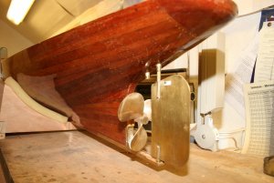
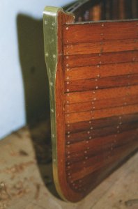
The parts I’m referring to are the protective brass strip down the stem, and the rudder with it’s supporting skeg.

The stem strip was tackled first, using 1.5mm strip brass, and a big file. The strip is 17mm wide over the stem-head, but then narrows down to about 6mm where the planking fairs into the stem, before slowly opening out again to the full width of the keel at the forefoot. The stem-head has a complicated double-reverse curve over the top, and I found the simplest way to achieve a really close fit was to bend the brass strip to the required shape, then sand the wooden stem-head to suit the pre-bent brass. When all was correct, the brass was bedded into wet varnish on the stem, and screwed down firmly.

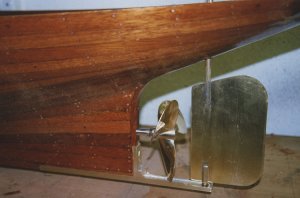
Next I tackled the skeg, which extends the line of the keel under the prop far enough to give a firm base for the bottom of the rudder shaft for the rudder. This was fabricated out of a sandwich of 15x15x1mm brass angle and 1.5mm brass strip, as I couldn’t get a suitable channel section, and incorporates a vertical section running from keel to the underside of the propshaft, mainly for strength, but it also looks good! Everything was bolted together, and then sweated with soft solder to give a firm fabrication.

The assembly was screwed into place, and then I carefully marked out the positions of the rudder tubes.

No, you haven’t miss-read – I did say tubes. Bat (On which ‘Natterer’ is based – come on!) has an ordinary rudder, which is mounted in the standard location, to the rear of the prop. However, she was at one stage owned by a gentleman called Kitchin, who used her as an experimental test-bed when he designed the Kitchin Rudder. This is a rather unique rudder which acts partly like a Kort rudder to give great manoeuverability, and partly like a jet engine’s thrust reversers, to give reverse motion with the propeller still running as if moving forward. The rudder was adopted experimentally in the Royal Navy for steam pinnaces and the like, but eventually fell out of favour as it was found that if the reverse was selected when running full ahead, the forces generated could (and did!) pull the transoms out of the boats. The forces are much less in model form, and the big advantage is that the boat can be put ahead, reversed and be held stationary in the water, just by operating the rudder and with the engine still running full ahead. This has great potential in a model steamboat application, as reversing a steam engine of the form being used can be tricky.

Anyway, the upshot of all this is that I wanted the ability to mount a Kitchin rudder if desired, and hence a second rudder tube had to go in forward of the normal one.

Both rudder tubes were drilled with the hull upside down, using a special long thin drill bit with the skeg as a guide, and then opened out to full size using a fabricated hollow drill cum hole-saw, slipped over the drill bit. Brass tubes were then glued in, to give perfectly aligned shafts.

Apart from the above, a little more work was carried out on the engine, with the result that the connecting rods were finally turned out of solid phosphor bronze stock. I then spent eight hours or so bedding in the crankshaft to the engine bed, and the con-rods to the crank, so there is no play or tight spots. A very boring operation, but one that has to be done to ensure the engine doesn’t knock itself apart in the first hour or two.

Natterer - Old013- resized.jpg

Natterer - Old012resized.jpg

The Kitchin Rudder


So what’s a Kitchin Rudder? Well, around the turn of the century (1900 that is), a gentleman by the name of Jack Kitchin lived at Windermere and designed a rather unique rudder and reversing gear for steam launches. Jack Kitchin did all his development work on his own steam launch – ‘Bat’, so at one stage she mounted a Kitchin rudder.

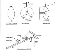
This device was made in two halves, each shaped as in Fig. 1, and curved so that when mounted on a boat, they formed a cylindrical shell, as Figs 2 & 3.

Each half of the rudder was controlled by separate shafts, one mounted within the other, and with two tillers.

The two tillers were connected to a yoke on a screw thread, which was itself mounted on a single tiller extension, as Fig 4.

Kitchin Rudder1resized.jpg

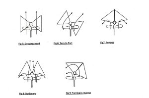
When moving forwards, the water flow is straight through the rudder, as Fig 5, but if the tiller bar is moved to port and starboard, then both halves of the rudder move together as a cylinder as in Fig 6, and the prop wash is deflected to one side or the other so as to steer the boat.

If however the tiller is held central and the handscrew wound anticlockwise, then the two halves of the rudder move back and together so as to meet behind the prop as in Fig. 7. The nett result is that the prop wash is deflected forward out of the rudder and the boat moves back.

A little thought will establish that the engine can be run ahead all the time, and that it is possible to find a position for the rudders as in Fig. 8, where the prop wash through the back of the rudders is balanced by the forward deflected prop wash so that the boat stays stationary in the water.

Now the really clever bit is that by combining the rudder effect and the reversing effect together, it is possible to reverse the boat and steer at the same time, as Fig.9, so that precise reverse steering is obtained! (also presents a nice little conundrum – in the illustration is the boat moving backwards to Port, as it is the port side of the boat, or to Starboard, as the stern is moving to the right?)

Kitchin Rudder2 resized.jpg


The rudder was adopted experimentally by the Royal Navy, but fell out of use before the second world war.

Kitchin was a prolific inventor, and was the first to control a boat (Bat again!) using radio control in 1904 from the top of Queen Adelaide’s Hill above Windermere. Apparently he stuck his gardener in the boat with instructions to keep stoking the boiler and touch nothing else – the man was terrified as he was sailed all over the lake!


‘Natterer’ – A shipbuilding Odyssey? – Part 8

I concluded the last piece with a short piece on the mechanism and operation of the Kitchin Rudder, which I was contemplating trying out on ‘Natterer’. Well, that was the idea, but I commenced by building a mock-up using stiff card, and concluded that whilst everything would fit, and the rudder would probably work, it all looked rather oversized. It didn’t look good, so I temporarily put that particular part of the project into abeyance, and proceeded with the conventional rudder for the time being. Might still come back to it as an experiment later!

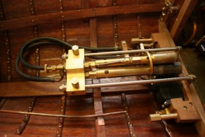
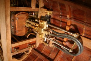
I now concentrated on the completion of the engine, together with the construction, from castings, of the boiler feed-water pump. The pump is used to continuously top-up the boiler whilst under way, and is driven off the main crank via a worm and spur gear. The castings were originally produced as an accessory for Stuart Turner’s Double Ten Steam Engine, so I had to modify the mountings somewhat to fit the Launch Engine, and also machine the bore oversize to increase the capacity.

Talking of bores (hopefully not this meandering narrative) I’d realised as I investigated the boiler that the Stuart launch engine was much more powerful than I needed, and that it would consume an awful lot of steam. The solution was to sleeve down the bores from 1” to ¾”, which reduced the power somewhat, but more importantly, halved the steam consumption to a level the boiler could easily handle without running flat-out.

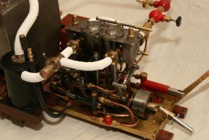
Once all the machining was completed the engine was fully dismantled, cleaned and painted, and re-assembled. It looked the part and came together very well. Initially very tight, as it should be, and I ran it on the lathe for about eight hours to loosen it up (I’d upgraded the lathe by now to a Chester!). Whilst being driven in this way, the engine actually acts as a pump, and I was getting quite a good suction on the inlet – boded well for the future, as leakage should be quite low when I eventually came to apply steam.

The engine runs at between 30 and 60 psi, so I didn’t envisage any problems in turning the crank – full 60psi pressure equates to a load of about 24 lbs on each piston face!

Time to test the engine! Rigged up an airline from the garage compressor, built up pressure to about 30psi, and cracked open the valve – IT WORKED! – It just started of it’s own accord, ran quite happily, and reversed with no problems when I pulled over the reverse lever. Jubilation – the crankshaft cranked, the valves valved, and the pistons – they worked too. Ann said my grin ran from ear to ear.

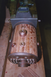
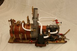
The other area I turned my attention to was the boiler, and here I installed superheater coils and feedwater heater coils in the smokebox. It looked like an absolute serpent’s nest of copper pipe, but at least it all fitted! In all likelyhood, the ‘superheater’ just acts as a steam drier, but never mind. At the other end of the boiler, I produced a facsimile of a full scale boiler face, with a fully riveted smokebox complete with lift up cover for access to clean the boiler tubes. All done in copper, later to be painted in special high temperature paint.

Talking of heat, I machined the mountings for the twin turbo gas torches that fire the beast – equivalent to two gas blowtorches working together – frightening – decided to call the burner ‘Smaug’

Next, it was time for a bit of testing and so tentatively turned up the heat on Smaug – thankfully it all worked, and I didn’t end up with a pile of smoking ash.

(I despair of Microsoft – their spell checker can’t even recognise words like “superheaters”, “lbs”, “smokebox”, etc. Doesn’t everybody use these words all the time?

IMG_1042.JPG


IMG_1056.JPG
No idea how this got turned sideways! - Shows burners slid forward to engage boiler.

IMG_3722.JPG

IMG_3721.JPG

IMG_3719.JPG

That's it for this session - more to follow

Ted
 
Many thanks Uwe!
My profession was in civil engineering, not mechanical, so although I did not have any training in machining, I have the sort of mind that is intensely interested in the way things work, and found it relatively easy to pick up all the techniques involved (My dad used to say I started taking things to bits at about six, and by eight was managing to put them together again!)

Ted
 
Incidentally, Uwe, how do I attach the list of models I'm either building or have built to the bottom of my posts?

Ted
Hallo Ted,
interesting the hear.... I am a Civil Engineer - but until now I would be not able to make such mechanical engines....... but maybe I should start.....the tools and equipment I have, due to the fact that I bought once from a modeler, who made model steam engines, his complete workshop......

To your question:

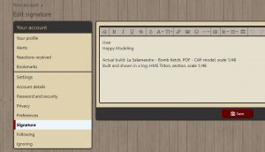
at the right top of the screen you have the link to your "personal account", for example I made a screenshot of mine

1.JPG

Here you find the link to "Signature"

2.JPG

Fill in, what you like and save it - afterword this signature is shown in your older and all new posts
 
Ted: You can include links to your build logs in your signature, also!
yes - take a look here:

link:
Unbenannt.JPG

Other BB-codes you can find at the bottom of the page under "terms and Rules"

Unbenannt1.JPG
 
Uwe and Dave,
Thanks for pointing me in the right direction! Have managed to add my builds.
- But I still can't get my head around the link instructions (probably something to do with the Abacus for a brain that I'm using)
Could you explain in words of one syllable to an idiot?
Ted
 
Back
Top