NHI Kolibri N-3, scale 1:48, scratch build

After having installed the collective controls and closed the torsion box, I changed my focus to the cockpit floor and the tail rotor controls. The four rudder pedals protrude through the floor and connect to two parallel shafts. On each shaft a lever is present, to which a control rod is attached. This control rod is then attached to another lever system in the main mast.

The cockpit floor is made from Evergreen ribbed sheet. It's left over material from my Fokker Spin build, which is now being put to good use. The forward edge of the floor is reinforced with a brass u-section; the Evergreen sheet is rather flimsy, when unsupported. Below a picture of the raw cut floor with the cut-outs for the rudder pedals:

View attachment 510805

In order to have a robust support for the two pedal shafts, I crafted a block with two dia 1.6mm holes, 2.5mm apart.
The two pictures below show this block with one of the shafts installed:

View attachment 510803View attachment 510806

The next picture shows the helicopter's fuselage with one of the shafts installed and in front of the helicopter the second shaft and two of the four pedals:
View attachment 510804

First dry fit of the floor and the rudder/tail rotor control system:
View attachment 510807

Fast forward a day and the second set of pedals have been made and the RH control rod. It's all a temporary fit, still a lot of work is needed to tidy it all up.
One of the issues I'm now encountering is to find the proper build sequence. Since a lot of parts need to share the same space, it's unavoidable to encounter sequence issues, for instance the fwd tank attachments occupy the fwd traverse landing gear spar. The floor with the rudder controls sit directly above the fwd spar. Installing the floor first results in limited access to the tank installation and vice versa. I guess I need a night's sleep over it...
Another emerging issue was that I added some external details to the torsion box, based on the isometric sketches I have, but those details were heavily interfering with the cockpit floor.

View attachment 510809

View attachment 510811

View attachment 510811

View attachment 510810
Very delicate and nicely scaled parts, Johan. And the sequence of installation can give you a headache. But hopefully no sleepless nights.
I can almost she her turning left and right with those pedals.
Regards, Peter
 
IMG_0750.jpeg
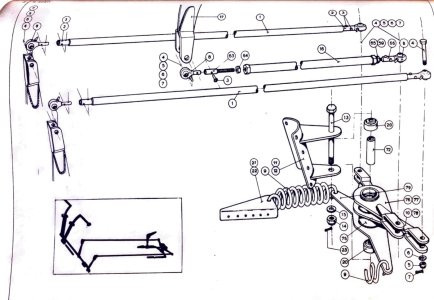
The above picture shows the main parts of the tail rotor control system. Not all parts are shown, but it gives you an idea about the complexity.
Clearly identifiable are the four pedal assemblies. There are two different assemblies, the RH and LH set of rudder pedals.
Then there are the two similar shaft assemblies with the control rods, which will drive the lever assembly, shown top center. This last assembly converts the fore and aft control inputs in the horizontal plane into an up- and down movement along the axis of the main mast.
You're looking at some 30 parts, pins, bolts and nuts excluded and I still need to fabricate a few parts...
I also use pin/hole connections to positively locate parts.
(The floor panel, center bottom, is shown for reference.)

One of the things worrying me right now is the possibility I might accumulate too much play, causing the whole thing not to work.
In real life this system would be loaded with bushes, bearings, washers, retaining rings, bolts, nuts, etc.
For modeling purposes it's essential to reduce parts count, or simplify the system, otherwise I would seriously damage the scale ratios.

To emphasize again, an awful lot of details are AL-FI, there's now way I can be absolutely certain about quite a few design details , but this build is turning out to be very demanding and very interesting.
 
Very delicate and nicely scaled parts, Johan. And the sequence of installation can give you a headache. But hopefully no sleepless nights.
I can almost she her turning left and right with those pedals.
Regards, Peter
Nice preservation of scale, Johan. Fiddly...
I know you will ultimately figure the sequence out. In the meantime, those floor pedals look great.
Those pedals are a precise engineering feat. Nicely done.

Jan
Can't say I have sleepless nights over this build, other than contemplating the next steps and how to proceed.
To stay true to scale is a major concern, selecting the wrong dimensions for parts may ruin the look I am after. This is not new; I had similar concerns with my Bluenose build, where I wanted to make sure the selected dimensions of amongst others blocks and ropes emphasized the true size of the Bluenose and not make it look smaller than she was.
It are pictures like the one below I use to fabricate the parts from, as you can see it's a lot of AL-FI...
IMG_1046.jpeg
 
View attachment 511067
The above picture shows the main parts of the tail rotor control system. Not all parts are shown, but it gives you an idea about the complexity.
Clearly identifiable are the four pedal assemblies. There are two different assemblies, the RH and LH set of rudder pedals.
Then there are the two similar shaft assemblies with the control rods, which will drive the lever assembly, shown top center. This last assembly converts the fore and aft control inputs in the horizontal plane into an up- and down movement along the axis of the main mast.
You're looking at some 30 parts, pins, bolts and nuts excluded and I still need to fabricate a few parts...
I also use pin/hole connections to positively locate parts.
(The floor panel, center bottom, is shown for reference.)

One of the things worrying me right now is the possibility I might accumulate too much play, causing the whole thing not to work.
In real life this system would be loaded with bushes, bearings, washers, retaining rings, bolts, nuts, etc.
For modeling purposes it's essential to reduce parts count, or simplify the system, otherwise I would seriously damage the scale ratios.

To emphasize again, an awful lot of details are AL-FI, there's now way I can be absolutely certain about quite a few design details , but this build is turning out to be very demanding and very interesting.
Good afternoon Johan. A very interesting build although something I would not attempt to do. I can see why this is a demanding build but that is how we all like it. If it was easy we wouldn’t be doing it - right? From my layperson point of view you are certainly on top of this. Enjoy. Cheers Grant
 
Good afternoon Johan. A very interesting build although something I would not attempt to do. I can see why this is a demanding build but that is how we all like it. If it was easy we wouldn’t be doing it - right? From my layperson point of view you are certainly on top of this. Enjoy. Cheers Grant
Really nice to see this "bird" taking shape. Intricate work, but well worth it. Hat off!
What can I say; despite everything I wrote to the contrary, I do like the challenge.
(And if they could build this 70 years ago in 1:1, I most definitely can build it in 1:24... )
 
Last edited:
Baai baai mooi Meneer. :D ROTF. Uitstekend. Cheers Grant

Looks great Johan!

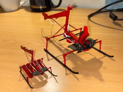
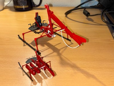
That looks very promising, Johan. The upscaling was a good decision. Nice to see the 2 scales side by side.
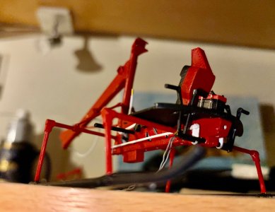
And that last picture is great!
The color combination of Red-Black-White is top.
Regards, Peter

That is awesome .

Jan

Awesome Johan! Where do the RC controls and servos go! :D

I agree with Peter
The colors red and white look good on your model
Nice progress
Regards
Henk

Dear Johan
it's looks amazing Thumbsup

Thank you for all the likes and compliments. It sure helps to keep me motivated to continue this build.
Sorry to disappoint you, @Daniel20, no room reserved for servos, so she's definitely not going to fly...
@Peter Voogt and @Henk Liebre, the colorscheme turned out to be beyond expectations; initially I set out for a dark blue, as one of her full scale predecessors wore, but that eliminated too many details. Red was the next color coming to mind; this matches with the color scheme of the Aviodrome Kolibri. The black for the floorboards was apparent in quite a few pictures, so that was a no-brainer as well. As for the white of the flight control rods and levers, well, if cracks occur in mentioned rods and levers, those cracks are way more easily detected in white than they would be if these parts had a black finish, hence the white finish.

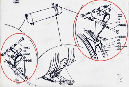
While on a short break, I have some time (;)) to think about some details,which are bothering me for some time now:
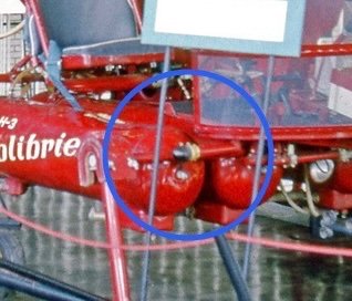
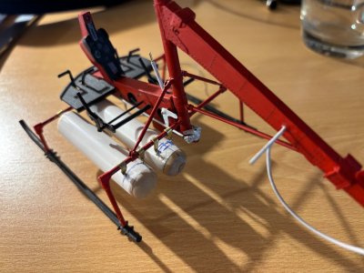
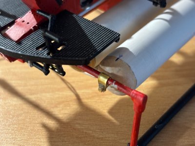
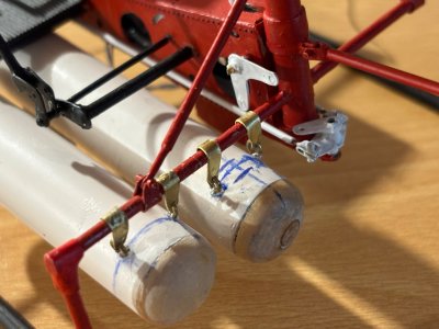
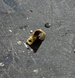
1) Front- and rear suspension of the fuel tanks. While I know the details, I'm still clueless on how to represent those convincingly in scale 1:24. The forward tank suspension is slightly less complicated than the aft tank suspension; it's a simple hinge point of which I need to fabricate four off. For the aft tank suspension I need to fabricate eight similar fittings with two hinges, a swivel and provisions to clamp the suspension assembly to the aft cross bar.
The LH bottom of the picture below shows the fwd suspension, whereas the RH top of the picture shows the aft suspension.

IMG_0936.jpeg
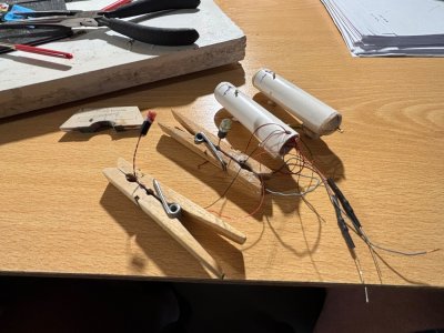
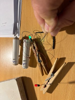
2) A second issue is the installation of the navigation lights. There are no sketches available, only photographic suggestions of those lights, only on the Aviodrome Kolibri, plus I need to get the wires and resistors out of sight. The lights are positioned just below the floor and slightly aft of the canopy attachment to the floor. Now the floor is installed I can play around with the lights installation and the routing of the wires.
Below a picture showing the starboard navigation light.

IMG_0783.jpeg
 
Back
Top