NHI Kolibri N-3, scale 1:48, scratch build

This week I started on something I've been postponing for quite some time now, namely the flight controls.
There is, as I mentioned before, very sparse information on this helicopter and that applies to essentially all details.
The first set of controls I need to be building is the collective pitch control of the main blades, since part of the system is housed inside the torsion box. I need this system in place in order to be able to close the torsion box, which in turn is needed to be closed to allow installation of the floor, seats and instrument panel. With me so far?

I have two drawings helping me out with respect to the collective controls on/in the torsion box. Upfront I'll tell you I will be deviating from these drawings, just to make it work...

Below, encircled in red, is the collective pitch control system.
View attachment 503691

And here an assembly drawing of the collective control, with the pushrods and levers, ultimately driving the control rod, attaching to the rotor head
View attachment 503689

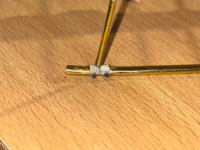
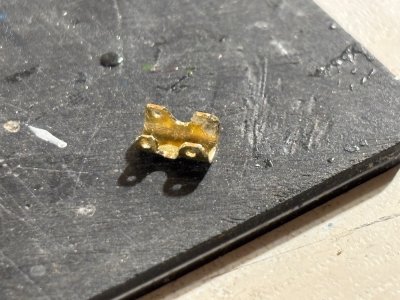
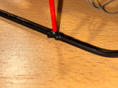
After a few days of fiddling and playing around a little bit, I came out with this:
It's a dry fit, so not everything is aligned properly, but this was just to ensure the fit and functionality of this part of the collective control system. The push rod nicely clears the shaft for the pilot seat support.
To make it even more complicated, the pitch control system of the tail rotor uses the same shaft (shown in the left hand side of the picture) as the levers and push rod of the collective. I have some ideas on how to tackle that issue, but first things first.

For reference: the pitch between the shafts and the push rod attachment is approx 4mm, 0,16".

View attachment 503695

View attachment 503696
Dear Johan
Great work on this interesting project
 
Below the translation of an article about the history of the Kolibri in Israel.
With permission of the author Avinoam Myasnikov and the much appreciated help of @shota70.
The article was originally posted on http://www.sky-high.co.il/

"Kolibri 4X-BEA

Story by: Avinoam Myasnikov
September 25, 2021
Article translated from Hebrew with Google translate by Johan Swart
Article originally published on https://sky-high.co.il/

Helicopter details:
Model: H-3 Kolibri
Manufacturer: NHI (Nederlandse Helikopter Industrie). Assembled by Aviolanda, Rotterdam, Netherlands
Manufacturer number: 3006

On February 26, 1958, the helicopter was registered with the Royal Netherlands Aviation Administration by the manufacturer under the registration mark PH-YMP. On March 27, 1958, it was registered in the name of the Dutch government, Ministry of Transport, Public Works and Water Management. The Dutch registration was canceled on April 4, 1963.
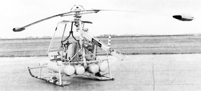
IMG_1036.jpeg

PH-YMP Kolibri photographed after its assembly
(Photo: Nico Terlouw)

History of the helicopter

In February 1958, a small airline company called “Wings of Israel” was established in Israel. The driving force behind the company was the late Jeremiah (or Jerry as everyone knew him) Renov, a pilot in the US Air Force during World War II, a pilot in the Israeli Air Force during the War of Independence and an instructor at the Air Force Flight School. Jerry was very interested in helicopters as platforms for aerial spraying, and a year after founding “Wings of Israel” he traveled to the Netherlands to closely examine the Kolibri helicopter. Upon his return to Israel, he brought with him not only the first helicopter of this type (4X-BEE) but also all the plans and in fact all the components of the production line, including the helicopter molds (Production Jigs), with the intention of continuing to build the helicopter in Israel and marketing it for military and civilianpurposes.

Of the 11 helicopters built, six were transferred to Israel, of which only four were airworthy and flew in practice. These were 4X-BDE which arrived in April 1959, 4X-BDA which arrived in May 1960, 4X-BDB which arrived in August 1962 and 4X-BDC in April 1963. Two additional helicopters were brought in complete condition but were never operated.

Jerry Renov's attempts to produce the helicopter in Israel were in vain. There were several reasons for this. First, there were more successful helicopters with conventional propulsion such as the Hebel 47 and the Alouette, and second, the market for this helicopter, which was limited inperformance and weak in engine power (60 hp per engine!) was not sufficient to justify serial production. Jerry's enthusiasm for the helicopter did not cease even when it was clear to him that he would have to settle for operating the helicopter rather than producing it. In an interview he gave in March 1967 to the British aviation magazine Aeroplane, he praised the helicopter. His attempts to offer the Kolibri to Chimavir and Marom Aerial Spray companies were rejected outright. Chimavir had already committed to purchasing Djinn helicopters that had previous experience in agricultural spraying in Europe, while Marom expressed no interest in the helicopter as an agricultural spraying platform at all, mainly because of the high maintenance costs.

In the first half of the 1960s, the Kolibri fleet accounted for 5% of the agricultural spraying segment in Israel, about one hundred flight hours per year. During the agriculturally “dead” months (December and January), the helicopters operated in the service of the Israel National Fund, spraying herbicides on forest fire trails throughout the country, but after a few years, the KKL-JNF preferred to carry out this activity from the ground, and Jerry returned to concentrating their activities on agricultural spraying in the summer months. The rest of the time was spent taking aerial photographs and dragging advertising posters. In Renov's opinion, the Kolibri failed because of its high price (about $23,000 without the spraying equipment), even though he estimated the market at two hundred units, and if he had succeeded in producing them in Israel, the cost would have dropped to $15,000 per helicopter.
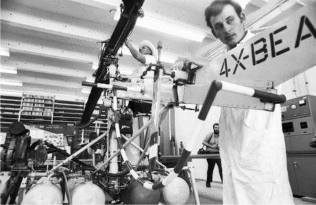
IMG_1037.jpeg
While performing maintenance work in Herzliya
(Harvard University Digital Collection)

The days, demonstrated the helicopter's performance to Col. Israel Ben-Amitai, the chief artillery officer at the time. The officers of the force were enthusiastic about its performance as a forward artillery observation helicopter, but the monopoly on operating military aircraft was in the hands of the Air Force, which already operated Alouette helicopters for this purpose, and showed no enthusiasm for adding an unusual and limited helicopter like the Kolibri to the IAF. Jerry Renov operated the last remaining Kolibri in the world (4X-BEA) for a while in the US where he had a subsidiary of "Wings of Israel", under the civil registration number N88983 registered in his name, but when the FAA (Federal Aviation Authority) refused to extend the validity of the helicopter's airworthiness certificate, they returned it to Israel, and operated it at the IAI MATA Jerusalem plant for testing purposes. The American registration was canceled on September 2, 1969.
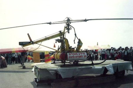
IMG_1038.jpeg
The hummingbird, still on American registration after its return from the US, on display
(Photo: Shaham Aloni)

In 1985, upon the expiration of the contract with IAI, the helicopter was transferred to the Air Force Museum in Hatzerim. The museum's commander, Yaakov Turner, accepted Jerry's request to store the helicopter in the museum, even though he was never a member of the Air Force's staff. The second surviving Hummingbird H-3 in the world is currently on loan from the Aviodrome museum (located at Lelystad Airport) to the Air- and War Museum on the island of Texel.

In the early 1990s, Jerry Renov's Hummingbird was removed from the Air Force Museum in a rather dilapidated condition. Although the Hummingbird was considered an efficient helicopter in terms of its performance in the field of agricultural spraying (it was a large consumer of fuel, 200 liters of fuel versus 200 liters of spray liquid!), it operated in the agricultural service for a very short period, less than seven consecutive years, and its operation was discontinued mainly because Jerry was an excellent pilot but a poor businessman, and was unable to operate his helicopters with the required profitability.
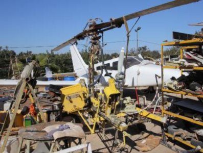
IMG_1039.jpeg
The remains of the helicopter were found at the “Avirom” company at the Herzliya airport.

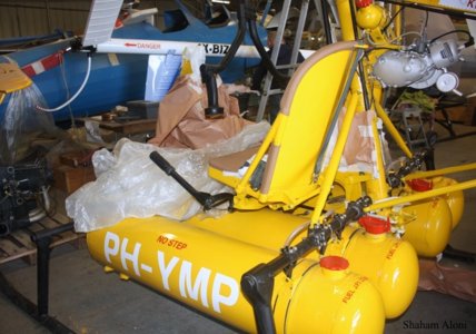
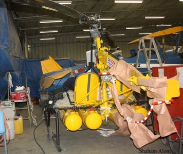
At a scrapyard in Herzliya Airport, the helicopter was refurbished for display at the “Avirom” company, and it was marked with the original Dutch civil registration markings.
IMG_1040.jpeg

IMG_1041.jpeg
The Hummingbird after the renovation at “Avirom".
(Photos: Shaham Aloni)"
 
Last edited:
Hey Henk,
Good to see you're alive and kicking.
I agree with you, those rivets turned out really well, with a big thank you for @Peter Voogt.
As stated before, it's a real challenging build, where I need to take time to work out many details, make prototype parts, threwing them in the bin and start again. That, combined with some anxiety as to whether or not I will be able to complete the model, makes this a nice pastime...
Kind regards, Johan
Yes,
Alive & Kicking (from the Simple Minds' biggest hit'

Threwing them in the bin and starting again.

In model building more rule than exception I have learned

The term Redo I got from you (haha)
Regards
Henk
 
Last edited:
At the moment there's no progress worth mentioning; I'm suffering from a builders block, or whatever you might call it. I'm stuck at the detailing of the struts and skids and the closing of the center torsion box. It's not that I'm abandoning this build, but getting the details right is a lot harder than I anticipated. Luckily my dear friend @Peter Voogt offered some great advice on how to proceed.

In the meantime I also started my work as a volunteer at the Aviodrome (the Dutch National Aviation Museum at Lelystad Airport).
I became member of the simulator group, offering flights to the visitors in one of the four available fixed base simulators. It's something I thoroughly enjoy doing. Whenever you're around, it's worth paying a visit to the Aviodrome.

IMG_0677.jpeg
 
At the moment there's no progress worth mentioning; I'm suffering from a builders block, or whatever you might call it. I'm stuck at the detailing of the struts and skids and the closing of the center torsion box. It's not that I'm abandoning this build, but getting the details right is a lot harder than I anticipated. Luckily my dear friend @Peter Voogt offered some great advice on how to proceed.

In the meantime I also started my work as a volunteer at the Aviodrome (the Dutch National Aviation Museum at Lelystad Airport).
I became member of the simulator group, offering flights to the visitors in one of the four available fixed base simulators. It's something I thoroughly enjoy doing. Whenever you're around, it's worth paying a visit to the Aviodrome.

View attachment 508269
Thats outstanding Johan!
 
At the moment there's no progress worth mentioning; I'm suffering from a builders block, or whatever you might call it. I'm stuck at the detailing of the struts and skids and the closing of the center torsion box. It's not that I'm abandoning this build, but getting the details right is a lot harder than I anticipated. Luckily my dear friend @Peter Voogt offered some great advice on how to proceed.

In the meantime I also started my work as a volunteer at the Aviodrome (the Dutch National Aviation Museum at Lelystad Airport).
I became member of the simulator group, offering flights to the visitors in one of the four available fixed base simulators. It's something I thoroughly enjoy doing. Whenever you're around, it's worth paying a visit to the Aviodrome.

View attachment 508269
Sometimes it goes up and sometimes it goed down with a build. A little rest and perhaps in a few days new energy, Johan.
And with some nice flights for sure you will get that.
Regards, Peter
 
At the moment there's no progress worth mentioning; I'm suffering from a builders block, or whatever you might call it. I'm stuck at the detailing of the struts and skids and the closing of the center torsion box. It's not that I'm abandoning this build, but getting the details right is a lot harder than I anticipated. Luckily my dear friend @Peter Voogt offered some great advice on how to proceed.

In the meantime I also started my work as a volunteer at the Aviodrome (the Dutch National Aviation Museum at Lelystad Airport).
I became member of the simulator group, offering flights to the visitors in one of the four available fixed base simulators. It's something I thoroughly enjoy doing. Whenever you're around, it's worth paying a visit to the Aviodrome.

View attachment 508269
my dear friend Johan
good luck in your new volunteer direction, I am sure that visitors to the museum will greatly benefit from your guidance and guidance. I hope to have the opportunity to visit the place and meet you.
 
I got some feedback from @Peter Voogt on the parts at the skid/strut interface. This led to the use of easy plyable material, which in turn led to an acceptable solution to a persistent issue.

Here the detail at the skid/strut interfac, based on Peter's help on this part:
(I also used dummy bolt heads on this interface)
IMG_0714.jpeg

Below one of the may failed attempts of brass made parts. I both used flat patterns and tube to get it right, but it all ended in failures (the part has a length of 6mm and an outer dia of 3,5mm):
IMG_0676.jpeg

Here the skid/strut interface with finish applied:
IMG_0717.jpeg

After having successfully tackled the previous issue, it was high time to continue work on the completion of the collective controls, which would allow me to (finally) close the torsion box.
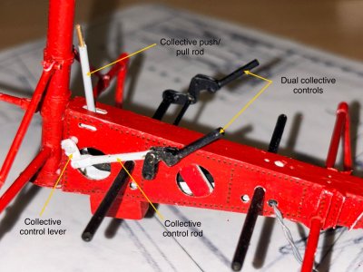
I first needed to have the RH collective control assembly and the collective push/pull control rod assembly installed, before attempting to install the LH side wall. This took quite some fiddling before everything lined up properly. If I were to attempt a second build, I would certainly forego the installation of lightsnand working controls; these ideas resulted in really complex build sequences.
Once having completed the torsion box assembly, I could now add the second (LH) collective control. I added an undocumented support, extending from the seat support beam, for the control shaft, for improved robustness.
The collective push/pull rod is split. Having a full length rod would be impossible to install, plus I don't yet know the exact length of this rod. The (unpainted) pin allows for a (later) male/female type connection.
IMG_0724.jpeg

A picture showing the current status of the fuselage assembly:
IMG_0722.jpeg
 
I got some feedback from @Peter Voogt on the parts at the skid/strut interface. This led to the use of easy plyable material, which in turn led to an acceptable solution to a persistent issue.

Here the detail at the skid/strut interfac, based on Peter's help on this part:
(I also used dummy bolt heads on this interface)
View attachment 509772

Below one of the may failed attempts of brass made parts. I both used flat patterns and tube to get it right, but it all ended in failures (the part has a length of 6mm and an outer dia of 3,5mm):
View attachment 509786

Here the skid/strut interface with finish applied:
View attachment 509773

After having successfully tackled the previous issue, it was high time to continue work on the completion of the collective controls, which would allow me to (finally) close the torsion box.
I first needed to have the RH collective control assembly and the collective push/pull control rod assembly installed, before attempting to install the LH side wall. This took quite some fiddling before everything lined up properly. If I were to attempt a second build, I would certainly forego the installation of lightsnand working controls; these ideas resulted in really complex build sequences.
Once having completed the torsion box assembly, I could now add the second (LH) collective control. I added an undocumented support, extending from the seat support beam, for the control shaft, for improved robustness.
The collective push/pull rod is split. Having a full length rod would be impossible to install, plus I don't yet know the exact length of this rod. The (unpainted) pin allows for a (later) male/female type connection.
View attachment 509787

A picture showing the current status of the fuselage assembly:
View attachment 509774
This is really amazing Johan, such tiny detail well executed. The skid /strut saddle connection with bolt heads, outstanding. Articulated collective controls again just outstanding.
 
I got some feedback from @Peter Voogt on the parts at the skid/strut interface. This led to the use of easy plyable material, which in turn led to an acceptable solution to a persistent issue.

Here the detail at the skid/strut interfac, based on Peter's help on this part:
(I also used dummy bolt heads on this interface)
View attachment 509772

Below one of the may failed attempts of brass made parts. I both used flat patterns and tube to get it right, but it all ended in failures (the part has a length of 6mm and an outer dia of 3,5mm):
View attachment 509786

Here the skid/strut interface with finish applied:
View attachment 509773

After having successfully tackled the previous issue, it was high time to continue work on the completion of the collective controls, which would allow me to (finally) close the torsion box.
I first needed to have the RH collective control assembly and the collective push/pull control rod assembly installed, before attempting to install the LH side wall. This took quite some fiddling before everything lined up properly. If I were to attempt a second build, I would certainly forego the installation of lightsnand working controls; these ideas resulted in really complex build sequences.
Once having completed the torsion box assembly, I could now add the second (LH) collective control. I added an undocumented support, extending from the seat support beam, for the control shaft, for improved robustness.
The collective push/pull rod is split. Having a full length rod would be impossible to install, plus I don't yet know the exact length of this rod. The (unpainted) pin allows for a (later) male/female type connection.
View attachment 509787

A picture showing the current status of the fuselage assembly:
View attachment 509774
It’s becoming more and more a real Kolibrie standing firmly on both legs, Johan. I am glad I could give some input.
Those collective are amazing (working) details!
Regards, Peter
 
I got some feedback from @Peter Voogt on the parts at the skid/strut interface. This led to the use of easy plyable material, which in turn led to an acceptable solution to a persistent issue.

Here the detail at the skid/strut interfac, based on Peter's help on this part:
(I also used dummy bolt heads on this interface)
View attachment 509772

Below one of the may failed attempts of brass made parts. I both used flat patterns and tube to get it right, but it all ended in failures (the part has a length of 6mm and an outer dia of 3,5mm):
View attachment 509786

Here the skid/strut interface with finish applied:
View attachment 509773

After having successfully tackled the previous issue, it was high time to continue work on the completion of the collective controls, which would allow me to (finally) close the torsion box.
I first needed to have the RH collective control assembly and the collective push/pull control rod assembly installed, before attempting to install the LH side wall. This took quite some fiddling before everything lined up properly. If I were to attempt a second build, I would certainly forego the installation of lightsnand working controls; these ideas resulted in really complex build sequences.
Once having completed the torsion box assembly, I could now add the second (LH) collective control. I added an undocumented support, extending from the seat support beam, for the control shaft, for improved robustness.
The collective push/pull rod is split. Having a full length rod would be impossible to install, plus I don't yet know the exact length of this rod. The (unpainted) pin allows for a (later) male/female type connection.
View attachment 509787

A picture showing the current status of the fuselage assembly:
View attachment 509774
Johan, my dear friend
We have all experienced the situation of dealing with a large or "small" part that requires patience, determination and creative thinking.
Dear friend, you have overcome the challenge with great success.
 
This is really amazing Johan, such tiny detail well executed. The skid /strut saddle connection with bolt heads, outstanding. Articulated collective controls again just outstanding.
Glad you found a solution that worked. I think it looks great! Sometimes a change in material used can be the difference. And if it’s painted, then something strong enough and workable is the best solution. Glad to see you moving forward again.
It’s becoming more and more a real Kolibrie standing firmly on both legs, Johan. I am glad I could give some input.
Those collective are amazing (working) details!
Regards, Peter
Johan, my dear friend
We have all experienced the situation of dealing with a large or "small" part that requires patience, determination and creative thinking.
Dear friend, you have overcome the challenge with great success.
While I truly appreciate your comments and positive feedback, I simultaneously have to admit that I am struggling with this model; the Kolibrie is fighting/challenging me every step of the way.
There are three main reasons for that, one, my limited experience with complex models, two, my wish to have working controls and three, the lack of drawings.
I'll leave the first two reasons for what they are and to the third one: in earlier discussions on someone else's blog I stated that sketches and drawings are not synonymous. Based on my current experiences with the Kolibrie I am more than confirmed in that statement regarding sketches and drawings.
While I do have an understanding of the general workings of this heli, many details are at best obscure. This means I frequently encounter details, especially in interface areas, where I experience the necessary surprises.
As an example, I started to prepare the work on the cockpit floors and the rudder pedals. I know how the rudder (tail rotor) system works and I know what the floors are supposed to look like, but... I don't have a single dimension and neither do I have something like an interface drawing or system install drawing.
At least these surprises cause my still present grey matter to be challenged, which is a good thing, according to my CFI.
And like I always say, there’s room for some AL (artistic license) ;)
 
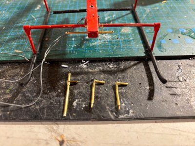
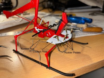
After having installed the collective controls and closed the torsion box, I changed my focus to the cockpit floor and the tail rotor controls. The four rudder pedals protrude through the floor and connect to two parallel shafts. On each shaft a lever is present, to which a control rod is attached. This control rod is then attached to another lever system in the main mast.

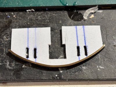
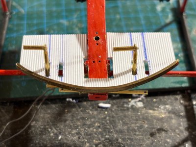
The cockpit floor is made from Evergreen ribbed sheet. It's left over material from my Fokker Spin build, which is now being put to good use. The forward edge of the floor is reinforced with a brass u-section; the Evergreen sheet is rather flimsy, when unsupported. Below a picture of the raw cut floor with the cut-outs for the rudder pedals:

IMG_0741.jpeg

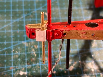
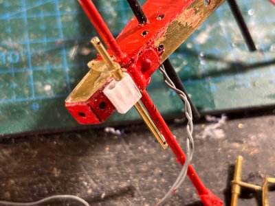
In order to have a robust support for the two pedal shafts, I crafted a block with two dia 1.6mm holes, 2.5mm apart.
The two pictures below show this block with one of the shafts installed:

IMG_0738.jpegIMG_0739.jpeg

The next picture shows the helicopter's fuselage with one of the shafts installed and in front of the helicopter the second shaft and two of the four pedals:
IMG_0737.jpeg

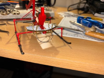
First dry fit of the floor and the rudder/tail rotor control system:
IMG_0742.jpeg

Fast forward a day and the second set of pedals have been made and the RH control rod. It's all a temporary fit, still a lot of work is needed to tidy it all up.
One of the issues I'm now encountering is to find the proper build sequence. Since a lot of parts need to share the same space, it's unavoidable to encounter sequence issues, for instance the fwd tank attachments occupy the fwd traverse landing gear spar. The floor with the rudder controls sit directly above the fwd spar. Installing the floor first results in limited access to the tank installation and vice versa. I guess I need a night's sleep over it...
Another emerging issue was that I added some external details to the torsion box, based on the isometric sketches I have, but those details were heavily interfering with the cockpit floor.

IMG_0747.jpeg

IMG_0748.jpeg

IMG_0748.jpeg

IMG_0746.jpeg
 
Last edited:
Back
Top