• Win a Free Custom Engraved Brass Coin!!!
    As a way to introduce our brass coins to the community, we will raffle off a free coin during the month of August. Follow link ABOVE for instructions for entering.

NHI Kolibri N-3, scale 1:48, scratch build

Modeling wise, I think I'm at the pivot point of the build; I now have to turn my attention towards the rotorhead and since I determined that I wanted to have functional flight controls, I manoeuvred myself in a tight corner.
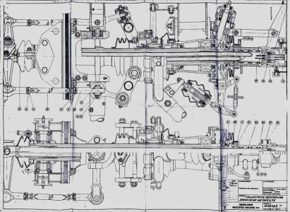
Basically all manoeuvrability and speed stems from the changing the (differential) pitch of the rotor blades (apart from the tail rotor, which controls the torsion around the vertical axis) and is accomplished through a complex system of linkages, connected to the collective pitch control lever and the cyclic controls, co trolled by the pilot. This all comes together in the rotorhead with shafts, both plane- and roller bearings, linkages, seas, fuel lines, ignition harnesses, main rotor axle, gears for the tail rotor drive, just to name a few of the components. Since the available space is quite limited, it's quite impossible to replicate all parts in scale 1:24. This means I have to make a simplified design for the rotor head and that's what I'm currently working on, without tangible results yet.
To give you an idea of the complexity of the rotorhead, the drawing below, which I was fortunate enough to obtain at the NLR, shows the details:
IMG_0020.jpeg

At the moment I'm considering a main shaft diameter of 3mm and a collective control shaft of 2mm, which leaves me with a 1 mm diameter free opening for fuel and ignition lines/harnesses. The first task I picked up was the simplified design of the controls for the collective pitch. It took me a couple of hours, but I still need to also determine the details for the other cyclic controls, before being able to start work on a physical model. And that's just one of the many challenges I'm facing. TBC.
 
Modeling wise, I think I'm at the pivot point of the build; I now have to turn my attention towards the rotorhead and since I determined that I wanted to have functional flight controls, I manoeuvred myself in a tight corner.
Basically all manoeuvrability and speed stems from the changing the (differential) pitch of the rotor blades (apart from the tail rotor, which controls the torsion around the vertical axis) and is accomplished through a complex system of linkages, connected to the collective pitch control lever and the cyclic controls, co trolled by the pilot. This all comes together in the rotorhead with shafts, both plane- and roller bearings, linkages, seas, fuel lines, ignition harnesses, main rotor axle, gears for the tail rotor drive, just to name a few of the components. Since the available space is quite limited, it's quite impossible to replicate all parts in scale 1:24. This means I have to make a simplified design for the rotor head and that's what I'm currently working on, without tangible results yet.
To give you an idea of the complexity of the rotorhead, the drawing below, which I was fortunate enough to obtain at the NLR, shows the details:

View attachment 535474

At the moment I'm considering a main shaft diameter of 3mm and a collective control shaft of 2mm, which leaves me with a 1 mm diameter free opening for fuel and ignition lines/harnesses. The first task I picked up was the simplified design of the controls for the collective pitch. It took me a couple of hours, but I still need to also determine the details for the other cyclic controls, before being able to start work on a physical model. And that's just one of the many challenges I'm facing. TBC.
Good afternoon Johan. Whew way above my pay grade. Looking forward to seeing how you achieve this.:D. Cheers Grant
 
Modeling wise, I think I'm at the pivot point of the build; I now have to turn my attention towards the rotorhead and since I determined that I wanted to have functional flight controls, I manoeuvred myself in a tight corner.
Basically all manoeuvrability and speed stems from the changing the (differential) pitch of the rotor blades (apart from the tail rotor, which controls the torsion around the vertical axis) and is accomplished through a complex system of linkages, connected to the collective pitch control lever and the cyclic controls, co trolled by the pilot. This all comes together in the rotorhead with shafts, both plane- and roller bearings, linkages, seas, fuel lines, ignition harnesses, main rotor axle, gears for the tail rotor drive, just to name a few of the components. Since the available space is quite limited, it's quite impossible to replicate all parts in scale 1:24. This means I have to make a simplified design for the rotor head and that's what I'm currently working on, without tangible results yet.
To give you an idea of the complexity of the rotorhead, the drawing below, which I was fortunate enough to obtain at the NLR, shows the details:

View attachment 535474

At the moment I'm considering a main shaft diameter of 3mm and a collective control shaft of 2mm, which leaves me with a 1 mm diameter free opening for fuel and ignition lines/harnesses. The first task I picked up was the simplified design of the controls for the collective pitch. It took me a couple of hours, but I still need to also determine the details for the other cyclic controls, before being able to start work on a physical model. And that's just one of the many challenges I'm facing. TBC.
This will be a great challenge, Johan. Indeed what you wrote, you have to simplify this technical part.
Regards, Peter
 
Modeling wise, I think I'm at the pivot point of the build; I now have to turn my attention towards the rotorhead and since I determined that I wanted to have functional flight controls, I manoeuvred myself in a tight corner.
Basically all manoeuvrability and speed stems from the changing the (differential) pitch of the rotor blades (apart from the tail rotor, which controls the torsion around the vertical axis) and is accomplished through a complex system of linkages, connected to the collective pitch control lever and the cyclic controls, co trolled by the pilot. This all comes together in the rotorhead with shafts, both plane- and roller bearings, linkages, seas, fuel lines, ignition harnesses, main rotor axle, gears for the tail rotor drive, just to name a few of the components. Since the available space is quite limited, it's quite impossible to replicate all parts in scale 1:24. This means I have to make a simplified design for the rotor head and that's what I'm currently working on, without tangible results yet.
To give you an idea of the complexity of the rotorhead, the drawing below, which I was fortunate enough to obtain at the NLR, shows the details:

View attachment 535474

At the moment I'm considering a main shaft diameter of 3mm and a collective control shaft of 2mm, which leaves me with a 1 mm diameter free opening for fuel and ignition lines/harnesses. The first task I picked up was the simplified design of the controls for the collective pitch. It took me a couple of hours, but I still need to also determine the details for the other cyclic controls, before being able to start work on a physical model. And that's just one of the many challenges I'm facing. TBC.
Apart from the staggering detail you are putting in your model, you are adding true complexity. Your 3 mm and 2 mm are extremely thin to accomplish any strength and sturdiness. And although you calculate having 1 mm space left, that probably will be split in two, if not four. Would photo etch or laser cutting be of help? Just thinking out loud.

Whatever: hat off.
 
What a daunting challenge Johan. I am looking forward to your solutions.
So am I, Dan, so am I...

Good afternoon Johan. Whew way above my pay grade. Looking forward to seeing how you achieve this.:D. Cheers Grant
Actually, it's above my pay grade as well...

This will be a great challenge, Johan. Indeed what you wrote, you have to simplify this technical part.
Regards, Peter
Simplification is the keyword here, it's impossible to replicate all details in 1:24.

Apart from the staggering detail you are putting in your model, you are adding true complexity. Your 3 mm and 2 mm are extremely thin to accomplish any strength and sturdiness. And although you calculate having 1 mm space left, that probably will be split in two, if not four. Would photo etch or laser cutting be of help? Just thinking out loud.

Whatever: hat off.

As a matter of fact the 2mm and 3mm axes don't need to take any large loads; it will just be the loads from using the flight controls and resistance in the total system. The 1mm space should be enough for feed through of some small dia wire, but you're right, it's definitely not much room to play with.
I haven't thought about the options you mention; instead I considered 3D printing, however, I convinced myself to forego on the new available technologies and instead try to accomplish this build the hard way...


In the mean time I started parts manufacturing, based on some sketches I made.
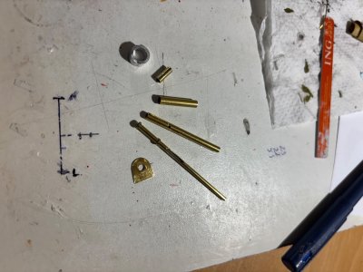
Below a picture of some parts for the rotorhead assembly:
- on top you'll find the housing of the gearbox, dia 8mm.
- next to it is the stationary part of the collective pitch adjustment, dia 2mm.
- below that part the main shaft in which the main axis rotates, this part is also considered to be a plain bearing for the main axis.
- the 3mm main axis is next and right below the main shaft.
- the 2mm rotating axis for the collective pitch adjustment. This axis has two slots through which a pin will connect the two axis together to ensure the two axes rotate at the same rpm and simultaneously allowing the inner axis to move up and down in the 3mm axis. Still with me?
- the bottom part is the part forming a) the cover of the gearbox and b) the connection to the main mast.

Next time I'll add some pictures of the sketches I made.


IMG_1191.jpeg
 
So am I, Dan, so am I...


Actually, it's above my pay grade as well...


Simplification is the keyword here, it's impossible to replicate all details in 1:24.


As a matter of fact the 2mm and 3mm axes don't need to take any large loads; it will just be the loads from using the flight controls and resistance in the total system. The 1mm space should be enough for feed through of some small dia wire, but you're right, it's definitely not much room to play with.
I haven't thought about the options you mention; instead I considered 3D printing, however, I convinced myself to forego on the new available technologies and instead try to accomplish this build the hard way...


In the mean time I started parts manufacturing, based on some sketches I made.
Below a picture of some parts for the rotorhead assembly:
- on top you'll find the housing of the gearbox, dia 8mm.
- next to it is the stationary part of the collective pitch adjustment, dia 2mm.
- below that part the main shaft in which the main axis rotates, this part is also considered to be a plain bearing for the main axis.
- the 3mm main axis is next and right below the main shaft.
- the 2mm rotating axis for the collective pitch adjustment. This axis has two slots through which a pin will connect the two axis together to ensure the two axes rotate at the same rpm and simultaneously allowing the inner axis to move up and down in the 3mm axis. Still with me?
- the bottom part is the part forming a) the cover of the gearbox and b) the connection to the main mast.

Next time I'll add some pictures of the sketches I made.


View attachment 536046
I can see that you have made your plan, Johan. The start of this new charter is there! Looking forward to see your sketches.
Regards, Peter
 
Last edited:
So am I, Dan, so am I...


Actually, it's above my pay grade as well...


Simplification is the keyword here, it's impossible to replicate all details in 1:24.


As a matter of fact the 2mm and 3mm axes don't need to take any large loads; it will just be the loads from using the flight controls and resistance in the total system. The 1mm space should be enough for feed through of some small dia wire, but you're right, it's definitely not much room to play with.
I haven't thought about the options you mention; instead I considered 3D printing, however, I convinced myself to forego on the new available technologies and instead try to accomplish this build the hard way...


In the mean time I started parts manufacturing, based on some sketches I made.
Below a picture of some parts for the rotorhead assembly:
- on top you'll find the housing of the gearbox, dia 8mm.
- next to it is the stationary part of the collective pitch adjustment, dia 2mm.
- below that part the main shaft in which the main axis rotates, this part is also considered to be a plain bearing for the main axis.
- the 3mm main axis is next and right below the main shaft.
- the 2mm rotating axis for the collective pitch adjustment. This axis has two slots through which a pin will connect the two axis together to ensure the two axes rotate at the same rpm and simultaneously allowing the inner axis to move up and down in the 3mm axis. Still with me?
- the bottom part is the part forming a) the cover of the gearbox and b) the connection to the main mast.

Next time I'll add some pictures of the sketches I made.


View attachment 536046
Hemeltjelief!
 
It's been a while since my last post here concerning the Kolibrie build. The delay is caused primarily by the complexity of the rotor head assembly and the need to downgrade said complexity to manageable levels. That took an awful lot from my meagre grey matter; considering ideas, turning them over in my head, turn ideas into sketches with tentative dimensions, trying out some ideas and get back to square 1 and starting all over. Normally, before starting to turn ideas into sketches, I try to look at the subject from all angles to avoid impossible solutions.
I haven't documented all steps, necessary to make the lower part of the rotor head; I'm afraid it's a quite boring sequence of making a lot of small parts and trying to assemble these parts using a logical sequence, while establishing appropriate assembly methods. I tried to solder a few parts, but eventually CA saved the day.
Below a few pictures, showing some of the sketches I made and the resulting parts and assemblies.

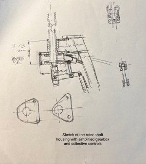
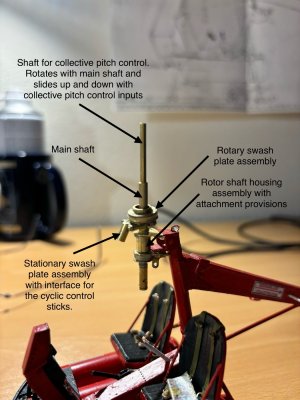
This sketch shows the rotor shaft housing with the collective controls and the flanges, attaching the rotor head to the rotor mast:

IMG_1283.jpeg

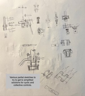
The next sketch shows the development of the swash plates for the cyclic control. Mind you, this is all a take away from the drawing I shared in post #301, with a lot of details omitted:
IMG_1284.jpeg

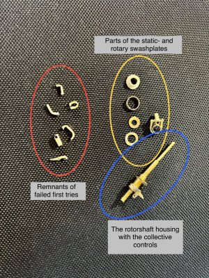
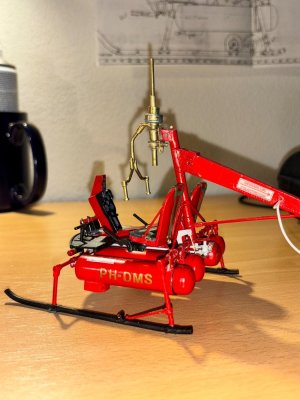
After some trial and error this was the result; quite a few scrap parts and a partially completed assembly:

IMG_1282.jpeg

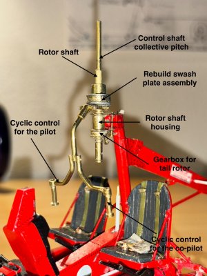
And below a dry fit of the shaft housing assembly with the collective pitch controls and the swash plate assembly.
My next step is to assess whether or not I'm at the stage where I can safely apply some finishing touches to this assembly and to permanently attach this to the rotor mast. Not sure yet...

IMG_1287.jpeg
 
It's been a while since my last post here concerning the Kolibrie build. The delay is caused primarily by the complexity of the rotor head assembly and the need to downgrade said complexity to manageable levels. That took an awful lot from my meagre grey matter; considering ideas, turning them over in my head, turn ideas into sketches with tentative dimensions, trying out some ideas and get back to square 1 and starting all over. Normally, before starting to turn ideas into sketches, I try to look at the subject from all angles to avoid impossible solutions.
I haven't documented all steps, necessary to make the lower part of the rotor head; I'm afraid it's a quite boring sequence of making a lot of small parts and trying to assemble these parts using a logical sequence, while establishing appropriate assembly methods. I tried to solder a few parts, but eventually CA saved the day.
Below a few pictures, showing some of the sketches I made and the resulting parts and assemblies.

This sketch shows the rotor shaft housing with the collective controls and the flanges, attaching the rotor head to the rotor mast:

View attachment 543053

The next sketch shows the development of the swash plates for the cyclic control. Mind you, this is all a take away from the drawing I shared in post #301, with a lot of details omitted:
View attachment 543054

After some trial and error this was the result; quite a few scrap parts and a partially completed assembly:

View attachment 543055

And below a dry fit of the shaft housing assembly with the collective pitch controls and the swash plate assembly.
My next step is to assess whether or not I'm at the stage where I can safely apply some finishing touches to this assembly and to permanently attach this to the rotor mast. Not sure yet...

View attachment 543056
Just opened the SoS on my hotelroom and saw you post from a few minutes ago. I make a deep bow for your approach for this very complex part, Johan. I have already seen the main shaft and know how small the parts are. I wish you all the toy-toy-toy for the assembly.
Regards, Peter
 
Just opened the SoS on my hotelroom and saw you post from a few minutes ago. I make a deep bow for your approach for this very complex part, Johan. I have already seen the main shaft and know how small the parts are. I wish you all the toy-toy-toy for the assembly.
Regards, Peter

Great work Johan, definitely not an enviable task! But your end result is sure to be a winner! ;)

Amazing detail Johan. l can see soldering has become second nature to you.

Ah, but the grey matter did a good job! Wonderful. And simplification without losing important detail is a complex task!

I’m humbled beyond belief

Thank y'all for your kind words!
Sometimes I think I should start applying 3D printed parts, much like @Marquinius is applying on his build, but until now I try to get the results using old fashioned handwork.

Soldering is a bit of a love/hate affair, too often, especially when using brass, heat transfer is a huge issue. Small parts to one another is doable, small parts on slightly larger assemblies not so much. I apparently need some more learning.

Smart simplification is essential for my purpose, so I need to try and understand the original design concept.

Finally, one of my character flaws is that I'm too stubborn for my own good. Whenever I'm faced with a challenge, I simply need to find a working solution, which sometimes requires a bit of time...
 
. Small parts to one another is doable, small parts on slightly larger assemblies not so much. I apparently need some more learning.
I’m reluctant to offer advice here because of my inexperience…but I have found success in the situation described above by only (mostly) heating the larger part until the solder flows.
 
Back
Top