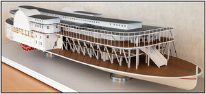
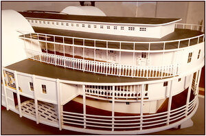
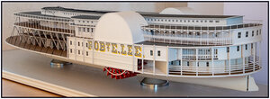
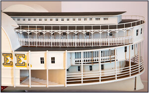
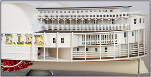
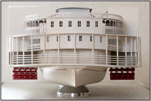
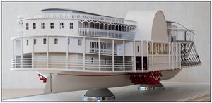
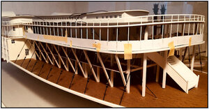
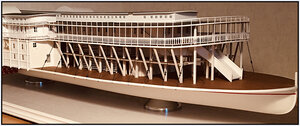
Paddle Steamer Robert E. Lee, scale 1:96, scratch build by the Alan L. Bates drawings [COMPLETED BUILD]

Hurricane Deck:
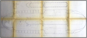
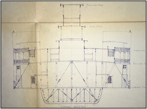
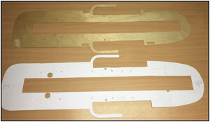
Sheet 6 shows the shape and structure of the Hurricane deck.
046 HurricainDeck0.jpg

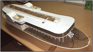
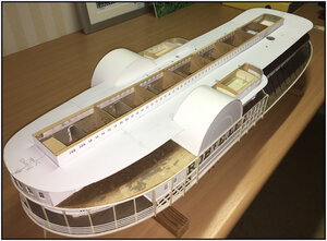
From several pieces of 120g paper I made the model of this deck. Everywhere along the curves cut as well as in the length direction fitting along the Main and Side Cabins and the Wheelhouses.
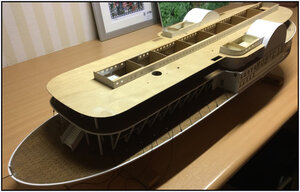
047 HurricainDeck1.JPG
048 HurricainDeck2.JPG

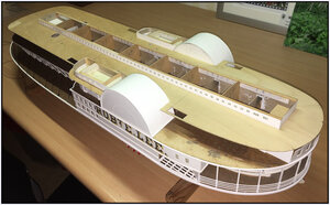
In the deck model I also applied the recesses for the Smokestacks, Bracings and Chains.
049 HurricainDeck3.JPG
 
Bracings and Chains:
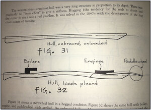
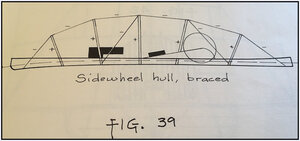
Because such a Paddle Steamer is a very large flat base, with a heavy Steam engine on about 1/3 of the front and on 1/3 of the rear the two Paddlewheels exerting a lot of force, then such a hull wants to deform.
With some pictures from the Bates Cyclopedeum.
053 Verstaging 3.JPG

Therefore, these Chains are applied in the transverse and longitudinal direction.
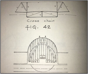
Traverse / Cross chains:
052 Verstaging2.JPG
Thee heavy paddlewheels of sidewheel boats were supported by a beam and truss arrangement.
051 Verstaging1.JPG

Longitudinal:
054 Verstaging 4.JPG

With the explanation in the Cyclopedium:
*Chains ALWAYS lift (-),
*Braces ALWAYS press down (+).
The – sign indicates tension, or pull, and the + sign means compression, or push.

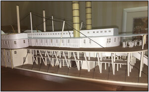
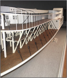
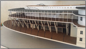
The Chains in the longitudinal direction and the standing Braces, over which the Chains pass, run from the hull through all the decks. They must therefore be aligned exactly by each deck.
050 HurricainDeck4.JPG
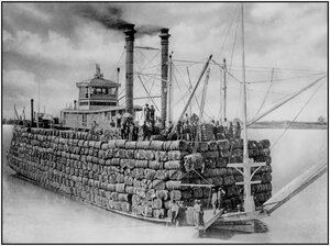
On the picture you also see all the cross chains witch supported the Main deck. Baled cotton was stacked on the flairing Main deck.
On Pinterest I found this picture. Very impressive!
050a Steamer met katoen.jpg
Alan Bates wrote in the Cyclopedeum:
The piles of bales of cotton were carried right up past the cabin and above the roof. Fully loaded, a cotton packet looked like an immense, floating cotton pile with stacks, pilothouse and wheelhouses being the only exposed parts of the boat. A passenger on a successful cotton boat could make an entire trip in the cabin without seeing the light of day.
 
Last edited:
Back to the Hurricane Deck.
I transferred the model to 1.3mm plywood and cut it out.
055 HurricainDeck5.JPG

After some sanding it quickly fit:
056 HurricainDeck6.JPG
057 HurricainDeck7.JPG

Because this deck is for the most part Hurricane roof, before gluing, the roof covering is first applied.
I made them out of anthracite (waterproof) sandpaper800. The sandpaper is first provided with 2 layers of clear lacquer. Because otherwise you see everything on it and the dust doesn't want to come off so well.
058 HurricainDeck8.JPG

When applying the deck, the deck on the model has different forces than the original.
Mainly because of the camber, the model deck wants to pull flat again.
What also plays on the Hurricane deck, is that the outsides are not supported by the hull. The ended free in space.

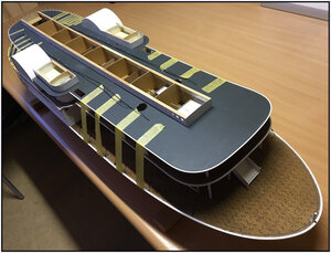
When applying and gluing the deck, I started with the inner sides along the Main Cabin.
I secured it with clamps pushing the deck downwards against the slats.
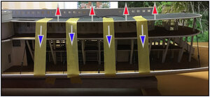
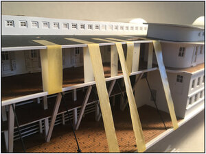
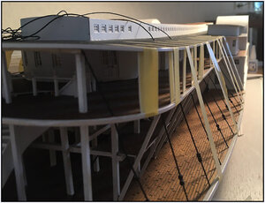
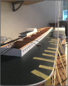
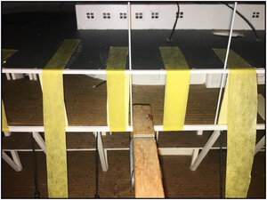
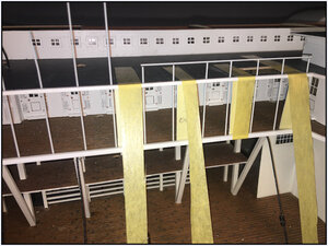
Then the outside edges are secured with tape, attached to the Main Deck. Because the outside of the deck also will push upwards.
059 HurricainDeck9.JPG
The red arrows: the force of the bended deck is pulling upwards.
The blue arrows: the tape is pulling downwards.

Once dry I started to apply the uprights from the entrenchment from the Boiler deck to the Hurricain Deck.
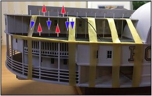
Due to the bonding on the Boilers Deck, and secured in the Hurricain Deck, the uprights serve as 'tow rods' to keep the 'straightening' sides of the deck in shape. The uprights are of 0.65mm Evergreen. Nice and thin to make the entire railings out of it. The multiness ensures that the forces are absorbed.
The top of the uprights is also the upright for the entrenchment of the Hurricane deck,
(With the original, all uprights support the Hurricane deck.)
060 Railing.JPG
By the model uprights:
The red arrows: The Hurricane deck pulls on the glued rods, and they are pulling on the upper side of Boiler deck.
The blue arrows: the glued rods pulls the Hurricane deck downwards.
 
Last edited:
Dust:
With the sandpaper deck cover, I was already talking about dust.
The years of standstill had a nice layer of dust and dirt deposited everywhere.
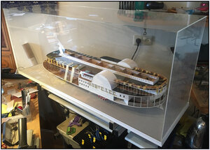
Therefore, first everything is cleaned properly and made a dust cover.
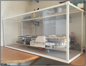
From 3mm plexiglass, all parts glued with chloroform. (Well ventilate well!).
062 Vitrine1.JPG

To give the whole a little body and stay in style, a frame made of corner profiles on the outside and round wood on the inside.
061 Vitrine2.JPG
Regards, Peter
 
Smokestacks:
In my post about the aligning of the braces and chains, you could see a part of the smokestacks.
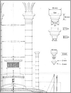
I made this one from just pvc electra tube, 19/17mm. Exactly the right size.
On the chimneys are so-called Puddings.
From the drawing the sizing is transferred and lathed out of round wood.
064 Puddings.jpg

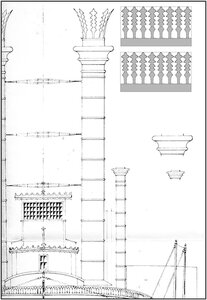
The Puddings have the Feathers.
This from the drawing transferred (2πr), printed on sheets and cut out.
063 Feathers.jpg

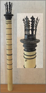
And around the Puddings:
065 SmokeStacks.jpg
After spraying, they need to be bent slightly. Therefore, on the inside with thin copper wire.

Around the chimneys are several Rolls. The interconnections between the parts.
In the PVC tubes thin cutouts filed and glued in it, all around, thin black PVC wire.
Also the eyes applied to which the tues will be stuck to secure the chimneys. Also made holes in which the 3 Spreaders will be in place: to secure the chimneys in respect of each other.
Regards, Peter
 
Excellent explanation of what you are doing. Learned something new.
Jan
You build a model for yourself. But you share your experience in a forum. To show how and what you have done and that others may also benefit from it. And how I managed scrath-problems, typical for this kind of boat.
(And there comes more problems, but later on ;))
@Jan: I'm glad there was something instructive about my posts.
Regards, Peter
 
Entrenchment - railing:
As mentioned, by the camber this deck wants back to its straight position. So I use the uprights as tow rods, with the underside glued to the Boiler deck and glued to the Hurricane deck.
To have the deck follow the sheer and holds its camber, I first fix it with tape to part the Boiler and partly the Main Deck. And used spacers between the Hurricane and Boiler deck so that the sheer and camber of both decks runs together. (The Boiler deck rests on the sloping braces):
066 Railing1.JPG
I do this up to the curve to the front:
067 Railing2.JPG

At the front, the deck is attached / glued to the 4 continuous uprights from the Main Deck with a carline above it with the camber.

Before applying the uprights, I had drilled holes every 14 mm along the edge of the Hurricane deck. All at odds with the waterline.
I then put a few pieces of rod 0.65mm through the holes and let them rest on the Boiler deck.
I then align this at right angles to the waterline and vertically on the longitudinal direction:
068 Railing3.JPG
069 Railing4.JPG
 
Last edited:
After aligning, I use a clothes pin to secure the position, because I pull the rod up slightly, apply glue to the bottom and on the sides where the rod protrudes through the Hurricane deck. I push it back into the right position and let the glue dry.
070 Railing5.JPG
I use long liquid stay CA, but when gluing and pressing, it quickly gets its adhesive power.
Once dry, I cut them off and make them at length. And always use a piece of rod to align them by length:
071 Railing6.JPG
Up to the front I did 24:
072 Railing7.JPG
Sheer and camber remain beautiful in it, although I say it myself ;)
Gives all in all some body and structure to the whole.
073 Railing8.JPG
After placing all of uprights, I was then able to shorten them all at the same length (=height) and apply the top railing.

Then the Sklights, the excellent inner part of the Main and Side cabins, features the Skylight Roofs. Cut out from 1mm plywood and also equipped with the 800 sandpaper with its 2 layers of clear lacquer.
That gives a more complete picture:
074 Railing-Sky.jpg

For this moment enough for the forum. Now its building time :)
Coming back soon.
Regards, Peter
 
Design and details of the railing:
The next step was how to place the railing with all of his details on the outside of the Boiler and Hurricane deck.
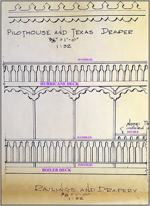
On 1 of the sheets a detailed drawing:
075 Railing Deco.jpg
-The Hurricane deck has a railing with a handrail and the vertical bars resting on the floor.
-Under the Hurricane deck a drapery.
-The Boiler deck has a railing with a hand- and a footrail, hanging above the floor.
-The Boiler deck on the back side has a double handrial.
The small vertical bars are at odds with the waterline, but sometimes a little skewed relative to the sheer and camber. Almost the same as the already installed upright rods.

In theory:
I have chosen for a ‘digital support’ and started on the rear left.
On the Boiler deck the railing is 20cm and on the Hurricane deck it is 26cm long.
From the wheel house to the middle of the rear cab, I installed a tape measure, horizontally aligned.
I place the camera also exactly horizontally. And at a fixed focal length, the camera focused between the Boiler and Hurricane deck, I take pictures every few cm in 9 steps, with always the tape measure in view.
In Photoshop I then merge the 9 photos and start compiling the railings and draper.

In practice:
Cut-outs of the photos 1:
076 Foto1.jpg
Foto 6:
077 Foto6.jpg
Foto 9:
078 Foto9.jpg
Each time the horizontal tape measure to support later on:
-precisely sticking together on the cm/mm,
-the horizontal alignment,
-lifting the distortion.
 
In steps in Photoshop:
-Using that tape measure, I was able to count each of the 9 photos back to the actual 1-to-1 size, where I came out just above 400ppi. Then they're exactly brought to 400ppi.
-Merged the 9 photos together to 1, aligned on the tape measure.
-To control and to completely eliminate the distortion in the curve at the rear, I scanned a lineal at 400ppi.
-I pasted that scanned lineal into the 1-to-9 photo row and further aligned the photos, where the tape measure on the model finally matched the scanned lineal.
-The final result should soon be a print in 400dpi, where the lineal on the photo is exactly right.
-With a lot of cut/paste I placed pieces of the sample drawing in the composite 1-to-9 photo, to compose the railings and drapers. All pieces always with the tools of Photoshop aligned to the shape of both decks. All in all in Photoshop a little 30 layers. These then merged together.

With an interim print and making some minor changes, this finally came to the screen.
Left rear:
079a Achter Links.jpg
And mirrored in Photoshop for right rear:
079b Achter Rechts.jpg
-At the bottom of both photos you can see the (grey) scanned lineal.
-At the Main-Cabin at the rear you can see a piece of the tape measure that was on the model.
Those two together aligned exactly on mm with the scanned lineal as standard.

Again in practice:
Then printed and the 3 parts cut lengthwise with rounding and fitted to the model:
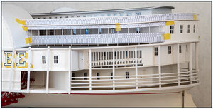
080 Railing Demo.jpg
But with one problem: I had already fitted the footrail of the Boiler deck railing on the model. The paper model didn't fit very well to that footrail :mad: Right isn't always right!
(Next time, use a better focal length of my lens, which gives less distortion. Is now very skewed left and right ;-)

The 3 parts also used for passing on the right side. Almost exactly: I made the model pretty symmetrical!!

With one of the extra prints, I first started to win back my skills with the scalpel knife to cut everything out. The bars are less than a mm, that will be a lot of patience exercise.
A piece with the front view above, with also that piece at the back. For what it's going to be.
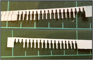
081 Test snijden.jpg
This test piece wasn't to my liking either :mad:. The railing has beautiful curves between the bars at the top and on either side of the bars.
That's not working with these mm scale out of hands.

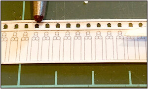
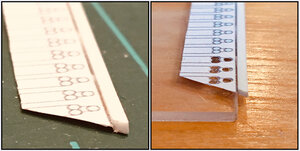
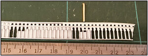
Then I thought of a hollow pipe. I had a piece of brass tube lying, inside 1mm. I beveled the sides of it on the outside to get a sharp edge.
Here the 1st tests are done (with the '20-cm' is the test hollow pipe) on a test-paper with already fitted the slats for the hand- and foot rails:
082 ProefMESSING.jpg
The principle worked, but a few problems emerged:
-after a few strokes, the end of the brass becomes a bit more blunt;
-1 mm is a little thicker than the drawn curves;
-the example from the sheets was drawn by hand around 1977. And then, when cutting out, it has the necessary irregularities which, once cut out, are only reinforced.
 
Last edited:
Back to the design:
That's why I got back to Photoshop to work and created a new design. With the rounds immediately indicated where I should hit with the hollow pipe:
083 SheetNIEUW.jpg
This again transferred to the 1-to-9 photo, copied at length and equipped with the curves of the sheer and camber.
As 1st started with the piece of railing left back/bottom, which also has an increased part.

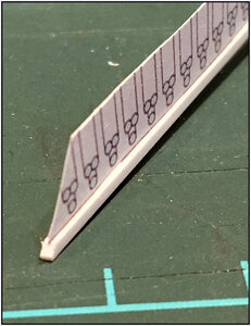
Printed out, cut out, the back already sprayed (gives some extra firmness) and equipped with the slats for the hand- and footrails. The advantage is, they also give the strip a bit more firmness.

Meanwhile on the internet also found a 'real' hollow pipe of 1mm and purchased.
With this, go to trial:
084 ProefHOLPIJP.jpg
In itself an acceptable result. The hollow pipe makes rounds of 1mm, similar to what I drew. However, the body of the hollow pipe is 6mm and runs at the end to the 1mm. When hitting the drawing upright, the thickness of the hollow pipe takes away the view on the drawing. You don't see where you put it and you quickly sit slightly beside the lines. With thick fingers and a pre-set glasses to do this needlework ............

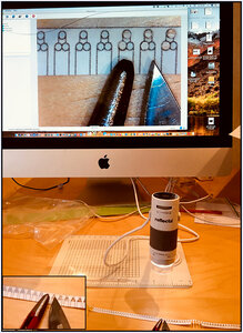
Found on the internet for a reasonable price a digital camera that can enlarge between 60x and 250x. With built-in lighting. Then it becomes a bit more pleasant working:
085 Hulpje.jpg
Connected to the Mac and you can suddenly work upright.
At the bottom of the picture a test strip with the hollow pipe and a scalpel knife. (A size-out in the lower left). On the Mac a nice sharp image.

After a little practice, you quickly manage to work through the screen and you know how to put the hollow pipe to make the rounds neatly 'within the lines'. Then cut out the rest with the scalpel blades through the lines. Support your hands and fingers well, as it is now clear up to 0.1 mm ;-)

After a few hours I had this piece of railing ready. The front also sprayed and applied to the model, where I had removed the foot railing:
086 RailingNIEUW.jpg
I'm not 100% satisfied, but this can go through with it.
With the experience of this 1st piece of railing, I can get started with all the other pieces. "Practice makes perfect".
Maybe after the tour I am so proficient that I also adjust the 1st piece of railing.

After an afternoon of cutting, slapping, cutting and spraying, the ornaments above the railing of the Boiler deck can be put on the left back. In addition, I was able to practice again the skills of working with 2 tweezers.
It fills the open spaces nicely and gives more line to the structure.
087 BoilerOrnament.jpg

At the start of construction, I thought a lot about how I was going to make this needlework of railings. I also thought about etchings, because a lot of years ago in a Dutch magazine "The Model builder" with a series of articles, attention was paid to this. But I didn't like the working with chemicals. Now with this 'old fashioned handwork' (and a little Photoshop) the beginning is made anyway. (Apart from the 2 small pieces on the 'TweenDeck' from many years ago).

Zoomed in a bit more:
088 BoilerOrnamentLA.jpg
PS-1:
For an indication of the dimensions: the uprights of the railing are 14 mm apart.
PS-2:
3 more hours and I'm at the 500 hours. (Thanks to the 'accounting' from 1987 ;-)
 
Last edited:
Railing on the Hurricane deck: a few steps back:
When placing the cut and painted railing on the Hurricane deck, the practice suddenly did not go along with what I had in theory figured out :(.
I thought I'd glue the railing under the already placed handrailing and tailor the possible length difference of all the bars, and then glue them on/against the white edge of the Hurricane deck. After a lot of fiddling and a result that became more and more disappointing to me, I was so dissatisfied with it, that I immediately took everything off and started to think again. With also a top railing with glue scraps ......

Restarted:
-first cut the 'old' handrail loosely from the uprights;
-the uprights all returned to 8mm height;
-the railing to be edited, cut out over the entire length at 8mm height;
-then glued in the middle on new handrailing strip of 1mmx1mm:
089 HurriRailing1.jpg

Lying flat, you can no longer hit the laps with the hollow pipe, because then it all rips loose again. But lying on the edge of a piece of plexiglass , that's the way it is:
090 HurriRailing2.jpg

A few hours further and front and back sprayed again, the 2nd attempt at placing on the model.
That went extremely well. Always a piece length of 3 uprights equipped with CA, the railing stick against the uprights and lower until the bars touch the deck. Once the CA was dry, the bars are provided with a tip of CA and with the help of the tweezers align and fasten. Even those bars once dry, it gave a straight and also solid result.
091 HurriRailing3.jpg

The starboard rear also done. All in all, quite a bit of work.
For a change a recording from a different perspective. The stern gets quite a bit of body:
092 Achterzijde.jpg
And one from right-back:
093 Re-Achterzijde.jpg
The lines of the sheer and the camber rounds make for a surprise in the photo every time.
There always seems to be some skew. Which is true in some cases. With 'the knowledge of today', 30 years ago I should have made the entrenchment on the 'TweenDeck in the wall something neater/straight.
But with the total picture, I'm still satisfied.
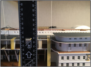
Now I have the advantage that the model is on its pedestals on the large display case-bottom plate and I can use the carpenter’s square much better to align everything.
The experience of the rear can now be taken to the front where longer stretches of railing can be made.
 
Last edited:
The contribution for today was 'a little longer'. And only for a small part of the boat.
But it's something that's obviously in sight.
I had to put a lot of creativity into that to get what I had in mind.

Now you've been updated to the current state of construction: making the railings on the front. Same practice, only make more (centi)meters!!

Regards, Peter
 
During the making of the posts above, I was still busy with the railing at the front of the Boiler and Hurricane deck.
For this part of the railings this time not with the merging of several photo.
From the making of the Main and Side cabins, I still have the paper molds.
I have used them to make molds for the railing and the drapers.
The first mold:
094 Rechtsvoor.jpg

Some different steps:
-the paper mold of the railing for the Boiler deck adjusted firmly with the sheer and camber of the deck;
-the mold used for a mold for the Drapers hanging under the Hurricane deck;
-a mold made for railing of the Hurricane deck.
-scanned them all and opened in Photoshop;
-my new railing design projected on this molds;
-printed out on 120gr paper;
-starting with the cutting rounds with the hollow pipe and cutting out the rest.

A piece of railing for the front: 2x next to the Side cabins, 2x straight and the front with 2 curves, is in total 115cm / 45,3in / 3,77ft long.
That's a lot of cutting rounds and cutting bars. The distance between the bars is 3mm.

After ‘some time’ you get this result for the railing, from the both Wheelhouse, along both Side cabins till the front of the Boiler deck:
095 Boil Voor.jpg

Now I'm working on the drapers above the railing, hanging under the Hurricane deck.
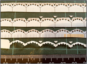
The different stages of cutting out.
The half rounds draws by Bates are slightly larger than 1mm. With the further cutting, I bring it in line:
096 Draper 4x.jpg

I’m still working for some time before these drapers are hanging.
When it's done, I will be back.
Regards, Peter
 
Thanks Jim and Uwe for the recent likes en reply.
Always nice to get a reaction on postings.

What one finds interesting doesn't have to be so for another.
This applies to both the type of boat or the materials and working methods used.
But maybe it's too extensive?
I try to keep the log interesting by explaining what and why I do things. ;)
Those are the pros and cons of scratch.
Regards, Peter
It is really interesting to see about the different problems a modeler of such a model has to solve.
At a Victory you have to rig 100 guns, making hundreds of gunport-lids etc.
Here you have to make hundreds of decoration elements on the railing - and you work here with different materials and different techniques
So one more log, where we all can learn something - opening the brain for something new Thumbsup
 
Back
Top