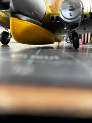
Revell B17-G Modified to a B17-H 1:48

Well, I'm glad I took the time to mask off the anti-glare areas and spray it out, there's practically no way I could make this be as smooth as it is with a brush. I will need to spray off the quarter sections of the engine cowlings as well.

View attachment 488922View attachment 488923View attachment 488924View attachment 488925

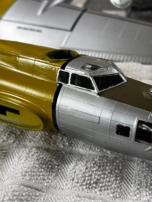
The next trick will be painting the windshields support framework an aluminum color. They made the framework integral with the clear windows. These close ups are very unforgiving, I constantly have to go back and do touch ups where the surfaces get nicked and bumped.
For now, it's back to the pinstriping and more painting.

Thanks for having a look.
For the windshield supports you may want to try bare metal foil a kind of adhesive aluminum foil you can cover the whole window with. Burnish it then cut out the foil covering the windows with a sharp scalpel.

 
Last edited:
For the windshield supports you may want to try bare metal foil a kind of adhesive aluminum foil you can cover the whole window with. Burnish it then cut out the foil covering the windows with a sharp scalpel.

What a novel idea Rob, thanks.
 
An interesting model, well done, and a nice tribute to your father.

I thought that you and your readers might be interested in the backstory behind the Airborne Lifeboat.

The Airbourne Lifeboat idea was originally developed by the RAF to save airmen ditching in cold North Sea waters. To design the boat, they turned to an interesting character by the name of Uffa Fox. Fox had earlier designed a revolutionary International 14 class sailboat that was capable of planing. (Scooting over the water, not plowing through it)

Fox's design was a modification of this basic International 14 design; the most notable modification being a modified sheer to mate with the belly of the Hudson bomber that carried it. Construction followed typical prewar sailing dinghy practice: two layers of mahogany planking laid diagonally with a layer of waterproofed fabric in between on closely spaced bent frames. The boat had a reinforced keel to which the parachute was attached. It was also designed to sail using sails, mast, and rigging carried aboard. The boat was credited with saving over 5000 airmen.

During the war, one of the Uffa Fox designed boats was sent to the USA where it was evaluated by another interesting character; Andrew Jackson Higgins, the inventor of the LCVP landing craft. Higgins supposedly decided that a boat with heavier construction was required for American use, so the American boats are much different.

Uffa Fox’s basic international 14 dinghy design was the basis for many popular racing classes in Britain USA after the war. During the winter of 1960-61, my father and I built a Thistle class sailboat from a kit. While the hull was hot moulded mahogany plywood, instead of Fox’s plank on frame, the boat was basically a 17ft version his International 14 design. Thistles are still actively raced. The new boats are fiberglass, but the old “woodies” still win championships.

Roger
Hello Roger and welcome aboard. I am so glad you found my build log and thank you for that informative backstory. I am grateful I can share what I know from my dad's history as told to me by him, this amazing forum gives all of us the opportunity to do the same.
 
A Coda to my Airborne Lifeboat backstory: In 2019 my wife and I were completing a wonderful tour of Scotland and decided to visit the Royal Yacht Britannia docked as a museum at Leith near Edinburg.

The ship is outfitted as if the Royal Family were still aboard. On the night table next to Prince Philip’s bed was a stack of books. Through the glass, I could see that the top book was one of several written by none other than Uffa Fox. Later on deck, was a sailboat, perhaps 20-25ft long. The sign describing the boat explained that Prince Philip enjoyed sailing the boat with Uffa Fox.

Uffa Fox was a waterfront character, not aristocracy or nobility. That the two men were able to bond through a sport that they both loved says much about the character of both.

End of my meddling. Back to your build!

Roger
 
Not sure if I am clear here Rob. When I talk about art tape it's not for masking but stays on the model permanently as in pin striping. This pin striping will boarder the yellow and will be black in color.

Thought about that too Rob but trimming the gasket material in that direction would produce an uneven edge, right now the first uneven edge (vertical cut) is hidden from view. I thought about using the stronger neodymium magnets as well but did not want to take the chance of inadvertently leaning in too close to them because I have a pacemaker implant and I try to stay away from strong magnetic fields, who knows you know. Still, I do very much appreciate your helpful suggestions.
Still Dan, I think that Rob's suggestion might be the way forward. The upper edge of the life boat looks a bit too "clumsy", when compared to the old photographs. Especially if you want to increase the ground clearance, I think you have very few, if any options left.
 
Still Dan, I think that Rob's suggestion might be the way forward. The upper edge of the life boat looks a bit too "clumsy", when compared to the old photographs. Especially if you want to increase the ground clearance, I think you have very few, if any options left.
I agree the black foam is out of whack both for clearance and scale. I will address that probably as the last thing I do, for now I will complete the plane itself. I have lowered the center of the wheel hub at the landing gear by about a 1/4", trimming or changing out the rubber gasket would gain another 1/8". The actual boat has two 90 deg propellers protruding out the bottom and encased in a metal basket. I would love to have the room to add that feature but right now it looks doubtful.
 
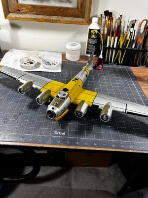
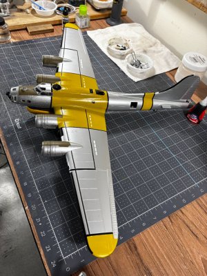
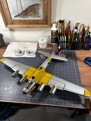
I wanted to show a dry fit up with completed pinstriping and painted in the deicers on the wings. I
am pleased with the overall look at this stage.

IMG_0696.jpgIMG_0699.jpgIMG_0700.jpgIMG_0701.jpg

Here is a current boat to ground clearance shot. It a little more than last time, about 3/8" but still not enough.IMG_0698.jpg

The decals are creeping into the back of my mind and I'm getting nervous about it. I remember them being very difficult in my youth.

Till next time thanks for looking in.
 
Dan,
Really shaping up nicely. You can eek out a little more height if you can get the wheels perpendicular to the tarmac. Also, I find running a toothpick around the insides of the window frames to be very helpful in getting a nice crip edge between the frames and the perspex.
 
I wanted to show a dry fit up with completed pinstriping and painted in the deicers on the wings. I
am pleased with the overall look at this stage.

View attachment 489177View attachment 489178View attachment 489179View attachment 489180

Here is a current boat to ground clearance shot. It a little more than last time, about 3/8" but still not enough.View attachment 489182

The decals are creeping into the back of my mind and I'm getting nervous about it. I remember them being very difficult in my youth.

Till next time thanks for looking in.
Love it - looks cool! Could you just find a piece of random black tubing and slit it on one side and slide it onto the boat? Scale looks off to me right now (?).
 
Love it - looks cool! Could you just find a piece of random black tubing and slit it on one side and slide it onto the boat? Scale looks off to me right now (?).
Paul,
That's a brilliant idea. Most hobby stores should have stuff used for representing hydraulic lines and such. Another (cheaper!) option could be to scrounge some black insulated wire (I've got yards of the stuff laying around) and pull the conductors out. It's tough to get any kind of adhesive to stick to either of those without making a huge mess, but I'll bet if some short pins of small diameter brass wire were inserted around the coaming the tubing pushed onto those to hold it in place.
 
Daniel, a tip on the decals…move them as little as possible on the model. I cut out the decal I am applying with an xacto knife and leave some excess around it, then soak until it starts to lift. Then remove from water still on the backing paper. Then I locate it on the model and grab one side gently with my finger tip or tweezers (depending on size) while I gently slide the backing paper out from under it. Then it should just land on the spot where you want it, and you can carefully adjust a little prior to letting it dry. This way you are less likely to tear or wrinkle up the decal. Hope I described the method well enough.
In addition, using decal set will make the decal conform to the surface better, as if it were painted on. Also cheap decals can be difficult to work with, so hopefully the kit includes some quality decals.
Decal softener/setter is a must for a good result. The best result would be to lay down a clear gloss coat first, put down your decals then another gloss coat over it. Without the gloss coat, silvering is always a potential issue.
 
You can eek out a little more height if you can get the wheels perpendicular to the tarmac.
Could you just find a piece of random black tubing and slit it on one side and slide it onto the boat?
Another (cheaper!) option could be to scrounge some black insulated wire
Thank you, gentlemen, all great suggestions. The wheels are slightly slanted in this dry fit up. I will have them square to the ground. Good suggestion about the toothpick Namabiiru I will try it.
 
Daniel, a tip on the decals…move them as little as possible on the model. I cut out the decal I am applying with an xacto knife and leave some excess around it, then soak until it starts to lift. Then remove from water still on the backing paper. Then I locate it on the model and grab one side gently with my finger tip or tweezers (depending on size) while I gently slide the backing paper out from under it. Then it should just land on the spot where you want it, and you can carefully adjust a little prior to letting it dry. This way you are less likely to tear or wrinkle up the decal. Hope I described the method well enough.
In addition, using decal set will make the decal conform to the surface better, as if it were painted on. Also cheap decals can be difficult to work with, so hopefully the kit includes some quality decals.
Thanks for the tip Dean.
 
Back
Top