SORRY"Victory" refers to "Victory Models", who make a kit for HMS Revenge.
-

Win a Free Custom Engraved Brass Coin!!!
As a way to introduce our brass coins to the community, we will raffle off a free coin during the month of August. Follow link ABOVE for instructions for entering.
You are using an out of date browser. It may not display this or other websites correctly.
You should upgrade or use an alternative browser.
You should upgrade or use an alternative browser.
Revenge by OcCre [COMPLETED BUILD]
- Thread starter Short John Bronze
- Start date
- Watchers 11
-
- Tags
- completed build occre revenge
SORRYVictory in this case is referring to the maker of the other model not the actual ship.
Amati Models - Revenge 1577 - Victory Models by Amati
Gun Carriages
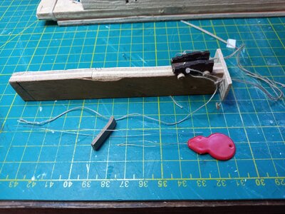
I tried a variety of sequences for rigging the gun tackles after attaching the carriage blocks. Eg starting by fixing the bulwark blocks or starting by fixing the flaked end of the rope to the deck. Because the gun carriages are light they kept flipping over and the tackles got twisted. If I fixed the carriages in place then access to the blocks was restricted. In the end (when I had almost done them all!) I made a simple jig so that I could pin down the carriage and rig an extended tackle (gun being loaded) much more easily. The rigged carriage could then be put in place and the ropes pulled taut. Pictured below.
Aside. In the first picture below the red needle threader is a type I have found very useful: a good long loop with a well pointed end. The other threader is a big eye threader (braced open with a scrap of wood) that I bought after reading about them somewhere in SOS. This is a bit tricky to grip but has the advantage that it is, in itself, a form of needle. It can be pushed right through a block rather than being pushed through, threaded and pulled back. It can be pushed through a sequence of blocks in turn without removing the thread each time.
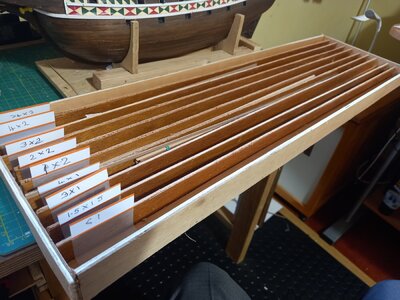
The second picture shows a storage tray I finally got round to making to hold all the non-planking strips for the current kit and left overs from earlier builds. No more fossicking about in a bundle of strips with caliper in hand searching for some 2x3mm rubbing strakes.


Rubbing strakes et al
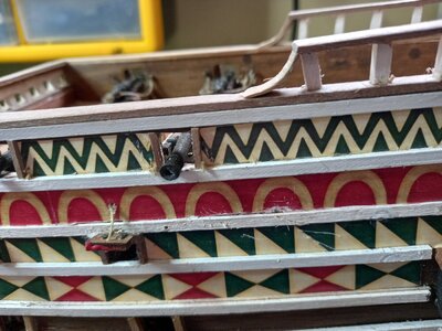
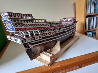
Like Richie before me I was a bit dubious about the quantity of white paint on the rubbing strakes but decided to go along with the notion that Sir Francis Drake had bought a job lot of Dulux. Rather than trying to paint the strakes after installation (hand-eye coordination ain't what it was) I painted three edges of the appropriate strips on the bench. Starting at the top of the gunwales I cut and applied the first decorative strip supplied in the kit and used its bottom edge as a guide for the first rubbing strake. I repeated this sequence - decoration + strake - down the hull past the gunports. It seemed to be easier than trying to fits the decorative strips beteen pairs of previously fitted strakes. The final result is a bit gaudy but makes a change from the models where I have tried to retain as much wood finish as possible.
Gun port lids.
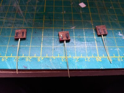
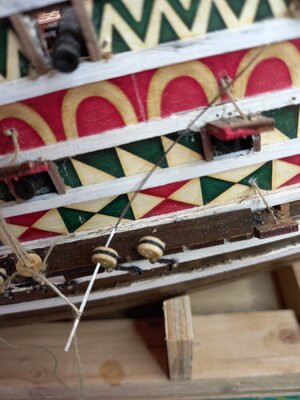
Rightly or wrongly I had cut the lower gunports so that they are immediately below a 2mm thick rubbing strake. This poses a problem of where to fit the gun port lids. Fitted to the edge of the rubbing strake they would patently not have swung down to fill the gunports. Glued to the underside of the strke they would be horizontal. I would prefer a slight uptilt. I resolved this by inserting a length of 0.6mm soft brass wire into the inner edge of the lids. The other end was glued into a hole drilled in the backing plate behind the gunports that receives the dummy cannon barrels. The lids could be tweaked to achieve the depth and angle that I wanted. The upper end of the lifting rope I poked into holes in the hull using a needle from which I had cut off the top of the eye. This formed a very small fork that could be withdrawn to leave the glue-smeared rope in place.
Gunwale top
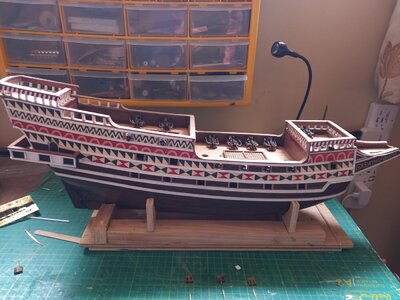
The gunwales are capped with 2 x 7 mm african walnut. Several sections are fitted to the tops of posts formed from 3 x 3mm limewood strip. I was abit concerned that a simple butt fitting at the lower end of the posts would make them a bit vulnerable to being knocked off when I start the rigging so I rounded the bottom 2mm of each post by bashing it into an improvised draw plate then drilled receiving holes in the top of the gunwales. (one of the photos below reveals that a bit of trimming is needed!)
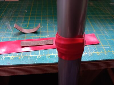
Where the levels change a curved section of gunwale cap is fitted. Bending these bits proved difficult even after extensive soaking. The resulting fractures of the underside are conveniently hidden by the decorative strips at the forecastle and quarterdeck but the ones on the poop are a bit exposed. In the end I thinned down the supplied strips and then glued two together in a curve. I taped them round a broom handle while the glue set. It seemed to work OK.


Deck and Hull fittings
This stage of a build I find the most enjoyable. There is a variety of tasks - cannon, gratings, gun port lids, chain plates etc with relatively little repetetive work. That said, there is just enough repetition to hone a technique and become more efficient e.g. making gun tackles. Time now to move on to the masts with the dreaded ratlines looming.
As an aside:
1) According to a web search, belaying pins are first referenced in 1745 so perhaps they should not appear on this and many other models.
2) Most models are made with guns run out ready for action so why do some have capstan bars fitted at the same time?
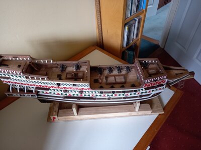
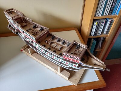


Many modelers tend to want to display contrary things like having the guns run out mixed with anchors being weighed or capstan arms in place, or hanging the sails in a position meant to dry them and not provide propulsion . The modeler is trying to display the ship in several modes of operation to show the various features of the model, and they frequently make no sense. The capstan bars should really not be installed without the hundred men manning the capstan, but modelers display them anyway.Deck and Hull fittings
This stage of a build I find the most enjoyable. There is a variety of tasks - cannon, gratings, gun port lids, chain plates etc with relatively little repetetive work. That said, there is just enough repetition to hone a technique and become more efficient e.g. making gun tackles. Time now to move on to the masts with the dreaded ratlines looming.
As an aside:
1) According to a web search, belaying pins are first referenced in 1745 so perhaps they should not appear on this and many other models.
2) Most models are made with guns run out ready for action so why do some have capstan bars fitted at the same time?
View attachment 368100 View attachment 368101
View attachment 368102
You as the modeler have to choose what to display based on the purpose of your model. Some display the ship as realistically as they can for one mode, such as sailed furled, or battle sails set for combat, or without sails to specifically display rigging and deck features. My last model had all sails fully deployed with yards set angled to take a light wind from the port quarter, all guns run out. But, there were extra things displayed that should not have been there, such as the capstan bars, lines and tackles used to telescope the top masts up into position, train tackles on all gun carriages, and fully deployed sprit topsail and lateen at the same time (one or the other is usually used to assist in turning the ship). Those were out of place, but showed more of the hardware that makes a working sailing vessel.
- Joined
- Aug 30, 2020
- Messages
- 676
- Points
- 353

Good job and look forward to see how you go with the rigging.Deck and Hull fittings
This stage of a build I find the most enjoyable. There is a variety of tasks - cannon, gratings, gun port lids, chain plates etc with relatively little repetetive work. That said, there is just enough repetition to hone a technique and become more efficient e.g. making gun tackles. Time now to move on to the masts with the dreaded ratlines looming.
As an aside:
1) According to a web search, belaying pins are first referenced in 1745 so perhaps they should not appear on this and many other models.
2) Most models are made with guns run out ready for action so why do some have capstan bars fitted at the same time?
View attachment 368100 View attachment 368101
View attachment 368102
My build has stalled at this spot a bit scared if the rigging.
Dead Eyes
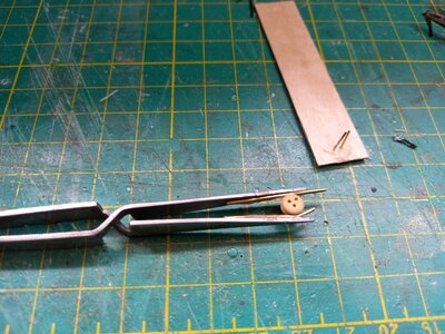
Bored with repeatedly hunting for dropped dead-eyes in a pile carpet I contrived a device for gripping them securely while processing them. Picture 1 below is a pair of tweezers with 1mm wire superglued to the inner surfaces. The wires fit into the groove round the dead-eye and stop it flipping out. The board in the picture with two pins is used to hold the dead-eye while the shroud or "chain" is attached. I guess we all have one of these.
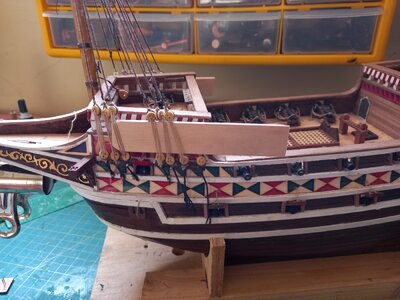
Every model I build I seem to try a different method of getting my dead-eyes in a line including: (1) shroud assembly on a bench top jig, (2) various wire contraptions, (3) pairs of pins on a board. Mixed Success. This time I tried using a wooden spacer with grooves in the edges to accommodate the attached threads. Picture 2 shows this applied to the foremast shrouds but I found it unhelpful. Aside: the spacing between upper an lower dead-eyes looks rather large to me but that is where the kit instructions seem to want them. Perhaps they did not have the standard formulae in the 16th century.
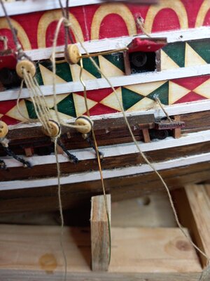
For the main shrouds I went for siplicity. for the first shroud of each pair I adjusted the lanyard to get the upper dead-eye at the chosen height. After passing the shroud round the cross trees I formed an adjustable loop at the other end. A dead-eye was fitted to the end of a bit of bent wire (picture 3) through two holes to maintain orientation. It was then put in the glue-smeared loop and pulled down to the required height. The loop was closed by pulling down the loosely placed lanyard.
The task of threading the lanyard was made very easy using the "big -eye" leedles I recently bought These are very thin, sharp and flexible. Usually I have difficulty threading the lower dead-eyes when they are attached to the chain plate. Either they have to be temporarily twisted to get a conventional needle threader through or the end of the lanyard has to be stiffened with glue before pushing it through the holes. The big-eye needles can be pushed through the lower dead-eyes, then bent to slide along the hull until the lanyard is pulled through. (Picture 4)They tend to spring straight after this operation though they do acquire an inconsequential permanent bend eventually.


Useful Hack
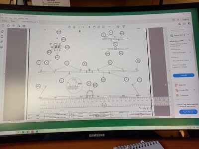
OcCre kindly provide a pdf of the plans and instructions for their kits. The masts and spars are on a sheet with 1:1 scale. I find it difficult to find clear space on my workbench to spread the paper sheets so a screen display is much more convenient. Scrolling is much easier than spreading another sheet. I have also found a widget that displays a ruler on screen to overlay the pdf. This can be moved with the mouse and switched between vertical and horizontal. Both pdf and ruler can be adjusted to get the scales coordinated. The picture below shows this combination being used to measure the posiutions of blocks on a yard arm.
Aside: One of my most useful tools is provided by the nails on my thumb and forefinger. Unfortunately they need to be trimmed now and then which renders them less useful for a few days.

Yes, they do. I have informed you of this several times and have many downloaded.Useful Hack
OcCre kindly provide a pdf of the plans and instructions for their kits. The masts and spars are on a sheet with 1:1 scale. I find it difficult to find clear space on my workbench to spread the paper sheets so a screen display is much more convenient. Scrolling is much easier than spreading another sheet. I have also found a widget that displays a ruler on screen to overlay the pdf. This can be moved with the mouse and switched between vertical and horizontal. Both pdf and ruler can be adjusted to get the scales coordinated. The picture below shows this combination being used to measure the posiutions of blocks on a yard arm.
Aside: One of my most useful tools is provided by the nails on my thumb and forefinger. Unfortunately they need to be trimmed now and then which renders them less useful for a few days.
View attachment 372762
Rigging sequence.
In previous models I have followed a fairly conventional sequence when doing the rigging: 1) assemble and fit complete masts 2) Standing rigging 3) Yards with or withouut sails. However, I have found that some of the standing rigging restricts access to the bitts and pin racks that receive the ends of the many halyards, lifts, clewlines and buntlines that are subsequently fitted. Especially hindering are the fore stays. Another issue is that my workbench, like many others, has a lot of small tools and fittings at the back. Reaching these without catching the t'gallant forestays is something at which I often fail. If I remember to avoid them when reaching forward then short term memory issues mean that I am likely to catch them when Iwithdraw my arm with an acquired tool.
So, I have decided to defer the fitting of forestays.
This means that I do not need to fit completed masts. I can start with just the lower masts and fit the shrouds (not a hindrance) and the yards and sails of the courses. (picture 1 below). Most of the running rigging for the yard and sail can be added - though not the braces which route via forestays.
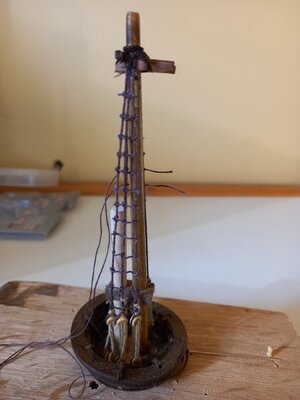
Also, I can assemble the top masts on the bench to be added later. The second picture shows the fore topmast being rigged. The unvarnished dowel is simulation of the top of the foremast. The crow's nest it temporarily pinned to the board. I might even add the topsail yard and sail with associated running rigging before I fit the whole assembly.
So far, so good. If I discover that this is a stupid idea I will report why in a future post.


Keep an eye on your shrouds as you do ratlines. Without forestays, the masts may start leaning rearward if the shrouds get tighter during ratlining. You should at least rig a temporary forestay while installing shrouds to keep the mast in position. That way, you can tension your shrouds proper without bending your mast, and take the forestay off after your are done. The mast may flex rearward a bit when you do that, but it will go back to the right position when you rig the permanent forestay.Rigging sequence.
In previous models I have followed a fairly conventional sequence when doing the rigging: 1) assemble and fit complete masts 2) Standing rigging 3) Yards with or withouut sails. However, I have found that some of the standing rigging restricts access to the bitts and pin racks that receive the ends of the many halyards, lifts, clewlines and buntlines that are subsequently fitted. Especially hindering are the fore stays. Another issue is that my workbench, like many others, has a lot of small tools and fittings at the back. Reaching these without catching the t'gallant forestays is something at which I often fail. If I remember to avoid them when reaching forward then short term memory issues mean that I am likely to catch them when Iwithdraw my arm with an acquired tool.
So, I have decided to defer the fitting of forestays.
This means that I do not need to fit completed masts. I can start with just the lower masts and fit the shrouds (not a hindrance) and the yards and sails of the courses. (picture 1 below). Most of the running rigging for the yard and sail can be added - though not the braces which route via forestays.
Also, I can assemble the top masts on the bench to be added later. The second picture shows the fore topmast being rigged. The unvarnished dowel is simulation of the top of the foremast. The crow's nest it temporarily pinned to the board. I might even add the topsail yard and sail with associated running rigging before I fit the whole assembly.
So far, so good. If I discover that this is a stupid idea I will report why in a future post.
View attachment 374759 View attachment 374760
Last edited:
Completely correct. The stays are there to support the masts. the former should do as must as possible with the yards-with or without sail -outside the ship (DRESSING THE YARDS) when the time comes with the yards dressed YOU only have to add the yards to the masts. there will be areas where there will be difficulties. many difficulties come from -according to instruction -are inserted the decks far too early.Kee an eye on your shrouds as you do ratlines. Without forestays, the masts may start leaning rearward if the shrouds get tighter during ratlining. You should at least rig a temporary forestay while installing shrouds to keep the mast in position. That way, you can tension your shrouds proper without bending your mast, and take the forestay off after your are done. The mast may flex rearward a bit when you do that, but it will go back to the right position when you rig the permanent forestay.
study well the instruction manual but do not always follow the sequence. insert a deck and then study it, if there are some fasting points etc. ass the rigging point now- the opposite way -. When one deck is done insert the next and so on. you may use this way more riggen lines, but. I never did make my shrouds totally finish -only hold the mast. In the end, I will totally complete them, after I have inserted the riggen lines here under the shrouds. the shrouds will over time slack a bit- the force -
Topmasts.
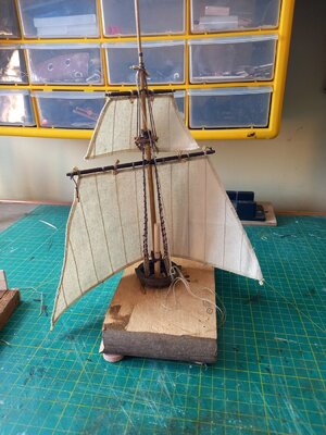
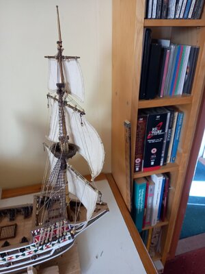
I have followed my decision to assemble the topmast and t'gallant mast assemblies in isolation and encountered no problems. It offered a number of advantages: tying the ratlines at bench level did not involve arm-aching reaching upwards; the simple jig was easier to turn round than the entire ship. The first photo below shows a completed assembly with main top and togallant masts, sails and yards. The running rigging is omitted at this stage apart from the halliards holding the yards in place. The sails have been hair-sprayed and blown dry. The second picture shows the equivalent assembly for the foremast after installation with the running rigging added. Belaying all the lifts, clewlines and buntlines was simplified by having delayed fitting the forestays. Braces will have to wait a bit longer.
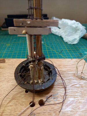
In previous models I have generally added ratlines working upwards from the dead-eyes. When tying the half hitch components of the clove hitches the needle has to be passed around the shroud and UNDER the bight of thread from the previous hich. this means that the loop has to be lifted. As the tatlines reach the point where the shrouds converge it is all too easy to tie two together unintentionally. I have now taken to tying the ratlines from top down which eliminates these problems. The needle is passed round the shroud and OVER the bight of thread which is obligingly hanging down. The needle can be passed round the shroud low down (where the spacing is wide) then run up to the level of the current ratline. This sequence made the adding of ratlines much easier. The third photo (a bit blurred I'm afraid) shows the use of a couple of simple spacers: tpairs of strips glued together at one end. The spacers control the separation of the ratline and preserve the spacing of the shrouds. The starting end of the ratline is temprarily secured by passing it through a hole in the spacer and pushing in a belaying pin. Half hitches formed below the lower space ar pulled taut just under it. Longer spacers are used where the shrouds are wider (e.g. main mast shrouds) with a securing clip at itheir open end.


LOOKS GOOD AND CORRECT TO METopmasts.
I have followed my decision to assemble the topmast and t'gallant mast assemblies in isolation and encountered no problems. It offered a number of advantages: tying the ratlines at bench level did not involve arm-aching reaching upwards; the simple jig was easier to turn round than the entire ship. The first photo below shows a completed assembly with main top and togallant masts, sails and yards. The running rigging is omitted at this stage apart from the halliards holding the yards in place. The sails have been hair-sprayed and blown dry. The second picture shows the equivalent assembly for the foremast after installation with the running rigging added. Belaying all the lifts, clewlines and buntlines was simplified by having delayed fitting the forestays. Braces will have to wait a bit longer.
In previous models I have generally added ratlines working upwards from the dead-eyes. When tying the half hitch components of the clove hitches the needle has to be passed around the shroud and UNDER the bight of thread from the previous hich. this means that the loop has to be lifted. As the tatlines reach the point where the shrouds converge it is all too easy to tie two together unintentionally. I have now taken to tying the ratlines from top down which eliminates these problems. The needle is passed round the shroud and OVER the bight of thread which is obligingly hanging down. The needle can be passed round the shroud low down (where the spacing is wide) then run up to the level of the current ratline. This sequence made the adding of ratlines much easier. The third photo (a bit blurred I'm afraid) shows the use of a couple of simple spacers: tpairs of strips glued together at one end. The spacers control the separation of the ratline and preserve the spacing of the shrouds. The starting end of the ratline is temprarily secured by passing it through a hole in the spacer and pushing in a belaying pin. Half hitches formed below the lower space ar pulled taut just under it. Longer spacers are used where the shrouds are wider (e.g. main mast shrouds) with a securing clip at itheir open end.
View attachment 377338 View attachment 377339 View attachment 377341
Belaying pins
I gather that in the real world a line is initially passed around the bottom end of a belaying pin then alternately round top and bottom until secure. This first step is difficult to perform on a model where the belaying pins are very close to the gunwale and are accessed either from above or from the opposite side of the ship. I have tried various hooks, probes, forks etc without much success. Given that belaying pins are probably an anacronism on the "Revenge" I have adopted a more pragmatic, less authentic approach.
There are various options.
1) if the other end of the line can be tied and its tension adjusted (eg at an eye bolt) then it can be tied round a belaying pin before it is inserted in the pin rack and then routed upwards.
2) If the other end of the line must be tied first then it can be passed through the appropriate blocks and finally threaded though the hole in the pin rack followed by inserting a (glued?) belaying pin.
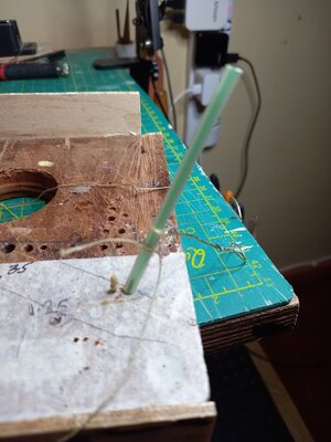
3) If the line terminates at a pin that is already in place then the method illustrated below can be used. The line is tied round a drinking straw using either a clove hitch or single overhand knot. The straw is placed over the top of the pin and the knot pushed down to the top of the pin rack. I use a wire loop for this. The knot is held down while the straw is removed then pulled tight or tweaked to adjust the tension.
On the OcCre model there are many cases where several lines end on the same pin. I'm not sure that this is realistic but option 3 helps to achieve it.
I have illustrated this by implementing it on the bench rather than on the model. There is one pin inside the straw.
A 'decorative' coil can be tied independently and added to the pin to hide the above bodges.

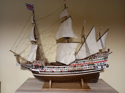
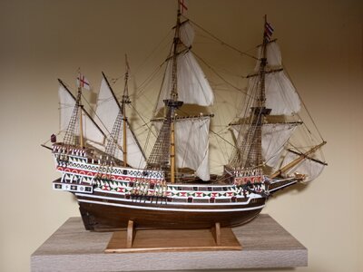
Launched
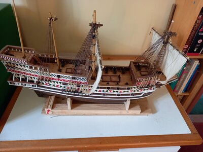
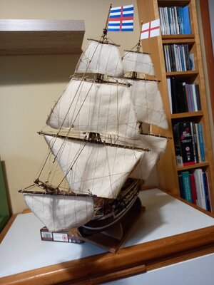
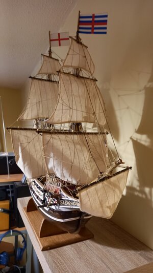
I had omitted the sails on most of my previous models. Including them on "Revenge" certainly added a lot of threading and knotting! One issue seemed to be getting the tension right between the 'active' lines of a ship under sail (sheets, tacks, bowlines) and the idle stuff such as buntlines and clew lines. I hope I have struck a reasonable balance. In general I got the sequence of adding spars, sails and rigging right with one or two exceptions. I added the flags as a final embellishment but getting the haliards down past all the other stuff to cleats at the foot of the masts was messy. With hindsight I should have added them earlier. They would then have acted as prominent markers for the top of the masts to avoid catching them when reaching over the model. There were some blocks attached near the top of the shrouds for routing the braces. I should have put those on earlier. Apart from these minor issues the rigging was not difficult and the OcCre intructions were quite explicit.
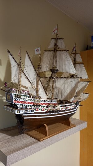
I decided to rig with the wind on the starboard quarter. This slightly reduces the distance between the hull and the wall so the stand is not too precariously near the edge of the shelf. It also gives the option of turning the model round occasionally to present a different view. With the wind on the quarter I assume the ship would heel so I have included (as a whimsy) a photo below with the stand tilted.
I notice that most models on the forum are mounted with the wind dead aft and the ship on an even keel. Very staid but not very dynamic! Has anyone actually made a display stand with the supports on a tilt?


Congratulations! An impressive display!


