.
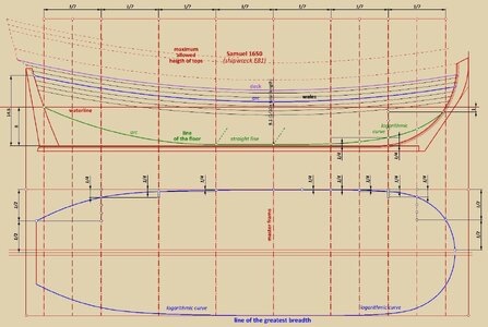
Now, the Holy Grail and the very essence of the quest in reverse engineering of old ship designs – the line of the floor and the line of the greatest breadth. Without the reconstruction of these lines, all that remains is a game of, shall we say, empirical nature, by forming shapes by eye, which, incidentally, may even at times produce quite decent results and, for example, an attractive model or painting, but will not, after all, answer the question of how ships were designed at the time.
According to the archaeological record, the following relationships and design sequence of
Samuel 1650 have been found or guessed, accurately or at least with a high degree of approximation:
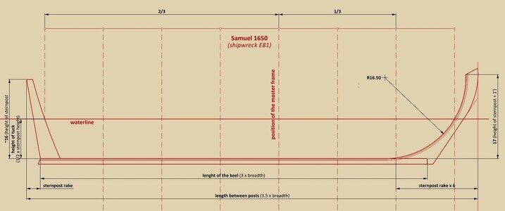
– the waterline level was set at eight feet, corresponding to the height of tuck (or
vice versa),
– the length of the waterline (not including the posts) has been divided into seven parts (with a subdivision of 14),
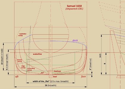
– at the stern, the line of the floor aft terminates at the height of tuck and, at the fore, one foot below the design waterline level; at the master frame deadrise has been fixed at three inches,
– the height of the greatest breadth at the master frame is 1/10 of the total length of the hull (i.e. between posts), about one foot above the design waterline,
– the wales are perfectly parallel to the line of greatest breadth (
scheerstrook, scheergang).
So much for the essentials of this rather simple design (in conceptual terms).
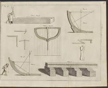
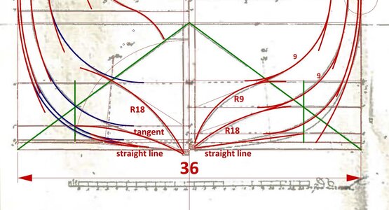
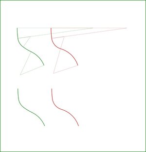
However, it should also be added that to form the shapes of the main design lines, logarithmic curves were extensively used. These are perhaps the easiest to use in practice, especially as they are ideally suited to achieving the contours of the frames straight away on the mould loft with a trivial simplicity, and without any real need to make any scale drawings on paper in advance.
.


