School for model ship building

As a result of reading Davis’s book I attempted, unsuccessfully to build a POF model. Hahn’s method offered something not described in Davis’s book; a way to align the frames. My next attempt using Hahn’s method produced a model that I am happy with. I believe that you judged it at one of the contests held at the Inland Seas Museum.

i did judge all the shows back then so most likely i did judge your model. there were. actually it was a panel of judges.

Since you knew Hahn well, I have a question that you can perhaps answer. To what extent was he influenced by Davis’s work and book? Was his method originally a way to improve on Davis’s work by adding the upside down building jig? If so it made building POF models practical for many of us.

it was Robert Bruckshaw that influenced Harold building in a jig. Bob used a floating sort of jig, i will see if i have a picture of one of his hulls under construction. Bob built models on private contracts and for the Smithsonian he had no interest in the hobby end, where Harold got into writing articles and books, drawing modeling plans and designing a method for hobby builders to succeed in plank on frame models. So Harold redesigned Bob's building method.

Relative to criticism directed at him for the double sistered frames: In the early 1970’s I don’t remember any American ship modelers publishing any research about actual Eighteenth Century framing practes. Later on, people began to criticize Davis’s reconstruction of the Brig Lexington including the double sistered frames. This spilled over to Hahn’s work as well.

back in the early 1970s there was little research and archaeological information in the hobby world of model ship building. It was all pretty much a mystery as to how ships were built. At an NRG conference Portia Takakjian introduced her model of the Essex which used the British system of framing of a sistered frame and single filler frames. When asked about why she chose that system of framing her answer was "because i like it" Later on when the Essex was published by Anatomy of the ship series the framing was changes to historically correct all sistered frames. The British version of framing caught on as a fad and somehow connected with the Admiralty models. At the time building English ship was all the rage and pretty mush still is. It is rare to find American built ships besides the Constitution and Rattlesnake. My guess English ships just looked pretty American ship were more practical they were ship of war and that was that, little gingerbread was added. You can see in the model Expo Confederacy using English framing a left over from an early fad and not realistic.
When the academic world of archaeology and the hobby of model shipbuilding began to overlap there was a flow of information. War of 1812 ship wrecks on the great lakes hum in the Great lakes all the ships even the British ones were all sistered framing.
Now we know better so we can build better and closer historical models.
 
Finally all caught up.

Recap of what I have learned so far as a complete newbie:
- the three parts of most drawings is a side view of the ship -obvious. The front and back view of the ship. Smashed together to look like one odd ship. One side will be the front, the other will be the back. The third drawing is from the bottom of the ship as if you were on the sea floor staring up at it. There are horizontal lines called waterlines that spread the three drawings to provide additional reference points to take a 2d drawing and make it 3d.

very good you get a gold star in class.

lets see a visual

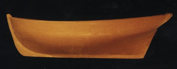
this is the outside profile. On a set of drawings you will get the wale, sheer line that is the top where the cap rail sits. Any gun ports if it is an armed vessel. and moldings

outside profile.jpg

when you cut a hull from bow to stern along the center of the keel it is the inside profile. On this view you will find the deck line, inside the bulkheads and any deck features like hatches, windlass location, deck house and location of deck beams.


inside profile.jpg

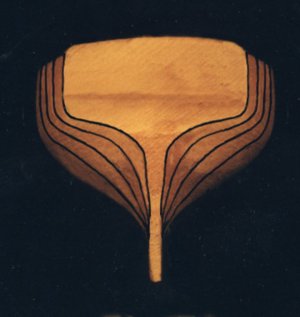
to get the shape of the hull you have a bodyplan from a view at the bow looking back to the stern

bow view.jpg

looking from the stern to the bow the bodyplan looks like this

stern view.jpg

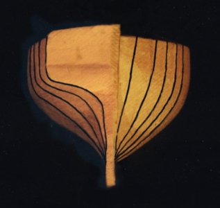
a draftsman will split the bodyplan on one side is the view from the stern and on the other side is a view from the bow

swplit bocy plan.jpg

a bodyplan will look like this

body plan.jpg

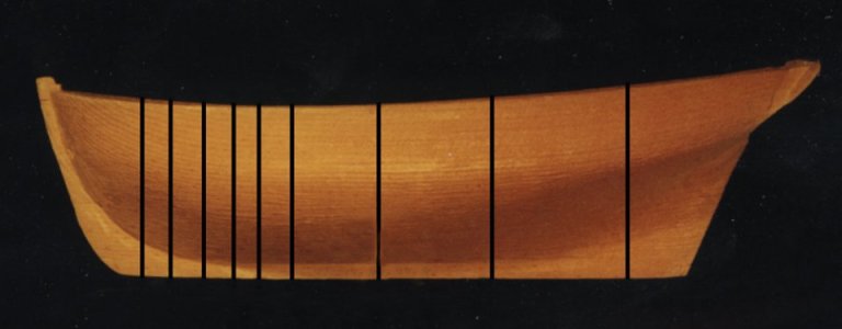
when you look at the profile it will show you the locations of the body lines called station lines. Where the hull takes a drastic change in shape like at the bow the station lines are placed closer together.

bodyplan side view.jpg

Standing at the bottom of the lake looking up you see this

bottom view.jpg

for the draftsman this view will show the shape of the hull from bow to stern. a plan will include the waterlines, deck line and sheer line.

waterlinesbottom view.jpg
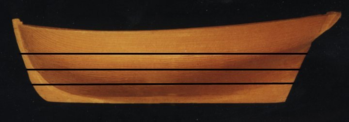
viewing the hull from the side the waterlines are a straight line. To build a half model or a lift model these two views gives you the shape and thickness for each lift. The more waterlines on the drawing the better you can define the shape of the hull.

water lines side view.jpg

the final view is looking down on the deck here the draftsman will add the deck features like hatches, fittings, deck house etc.

deck view.jpg
 
Last edited:
good job you are correct and if you have questions or need a better explanation post it that is why we are here.


There are horizontal lines called waterlines that spread the three drawings to provide additional reference points to take a 2d drawing and make it 3d.
- tools used don't have to be complex. To start with an exact knife and tongue depressors or coffee sticks will do the trick if you are strapped for cash but still want to learn. Personally I'm using scissors and cardboard for my first build but look forward to moving on to wood someday.
- there are lots of words I don't know. The ones I have figured out so far: Frame is uh... one of the ribs of the hull. Hull is the bottom of the boat. Aft is the back of the boat. Keel - the bottom center beam of the ship that the frames are attached too.
- frames are made by glueing up multiple cuts of wood together instead of one solid piece. It is ok to use one solid piece though if you aren't too concerned with accuracy or wood waste. The joints are offset to make each rib frame thing stronger.
- frames are set into the keel. You can attach them to the keel using a square of some sort or the jig that holds the tops in place and builds upsidedown
- cad makes it a lot easier especially if you have a friend with a laser cutter. However, tracing paper or holding printouts to a window or taking a piece of paper to a dark room and holding it over your computer/tablet screen also works to trace onto paper. Note - if your screen isn't glass like an iPad be very careful with the amount of pressure supplied to not ruin your screen.
- I'm sorry to hear of the loss of a great model builder. Thank you for teaching us what you learned to from him.
- everyone here is very passionate and polite even with different opinions which is super encouraging. Everyone can art is my belief for sure.
 
good morning model builders today we are going to assemble a laser cut frame

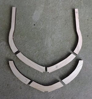
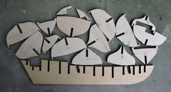
Each frame in the Hawke is made up of 7 pieces

laser frame2.jpg

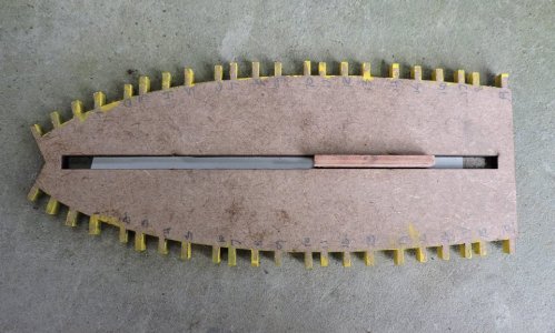
i will be using this jig to build each frame


laser frame1.jpg
 
Last edited:
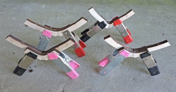
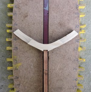
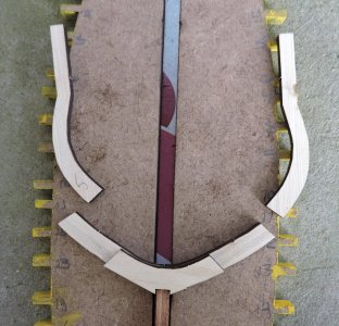
i began with gluing floor and the first futtocks together, this was done by just sighting in the edges and feeling the pieces to line them up. Then i glued and clamped the parts.

futtock is a term for the pieces that make up a frame

laser frame3.jpg

the bottom of the frame will sit on the jig with the notch fitting into the false keel which is in the slot running down the middle of the jig.
There is nothing to position the bottom of the frame to, it can move to either side.


laser frame4.jpglaser frame5.jpglaser frame6.jpg
 
Last edited:
The problem here is how to build each frame to exactly the correct shape and insure it will fit into the framing jig?

by using the top timbers, we can locate the exact position for the top of the frame as well as the foot of the top timber.

laser frame7.jpg

hum? how are we going to do this?

first locate the notch in the floor to the false keel. The slot running down the center of the jig is in the exact center so we now have a center point we will call point 1


laser frame9.jpg

next we need points 2 and 3 to get a 3 point position for the frame being built. Position the top timber on the edges of the notch tab.

laser frame10.jpg

what this will do is create a pivot point marked by the dots.

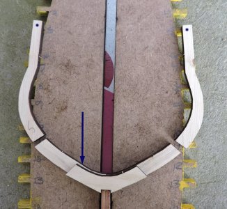
the blue arrow is pointing to a slight miss when i glued the first futtock to the floor.


laser frame8.jpg

The idea here is to build as accurate as possible. Each part relates to another part and so on and so forth. If your sloppy with your joinery it will just keep getting worse as the build proceeds. It does not matter if you are building from scratch or a kit it is about accuracy.
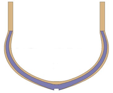
There is a margin of error a safe zone. In the picture below the dark frame shape is the finished actual size and shape of the frame. the brown is the safety zone built into the frame blank. Hahn added the extra in his original frame drawings and i kept it in the laser cut parts.
If you do miss a little when you build the frames just be sure your within the extra space.


frame size.jpg
 
Last edited:
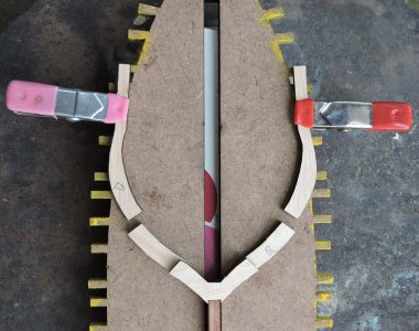
This operation is a fiddle about with the parts until you get them to line up. first line up the tops to the jig and clam them down.

laser frame14.jpg

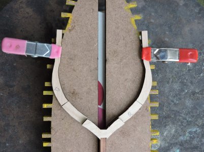
next slide the bottom part of the frame up to the foot of the top timbers. Here is where you have to a line the top timber to the bottom, By using the top as a pivot move the foot in or out until they line up on both sides with the floor
.

laser frame15.jpg

keep an eye on the top timbers and make sure they are lined up, if you are to forward your pulling the frame out of the keel notch

laser frame12.jpg

if you are too far in or out the frame will not fit into the jig notches

laser frame13.jpg

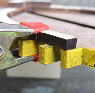
once everything is lined up i used a weight to hold the floor part down and clamped the top section to the jig

laser frame16.jpg

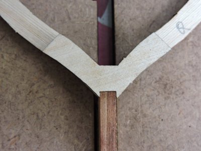
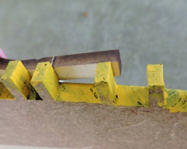
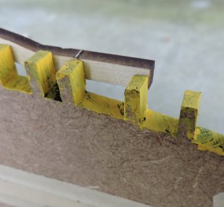
i am using Gorilla super glue and gluing the second futtock on to the frame. I tinted the second futtock on the right side. You can see the second futtock overlaps the floor section and the top timber creating a strong frame.

laser frame17.jpg
 
Last edited:
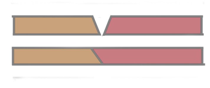
Lasers cut at a very small angle

laser angle.jpg

Check the fit of laser cut joinery the bottom example shows what a butt joint would look like if the pieces were put together like the top drawing.
If you took the red tinted piece and flipped it over to match the brown piece you will get a tighter fit like the sample below. you are looking very close to the frame parts but normal viewing even the wider joint is very small.


laser frame18.jpg

in the case of building the frames you can not just flip a piece over you have to flip the right piece to the left side and the left to the right.

laser frame19.jpg
 
Last edited:
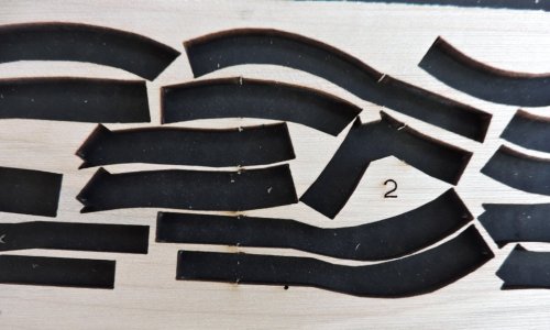
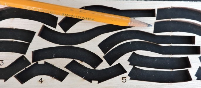
Designing a project such as this there are things to consider keeping costs as low as possible. In the examples the frame parts are nested as close together as possible. The more parts to fit per sheet the less number of sheets needed. The less number of sheets used the lighter the weight for shipping costs. The parts are so close together it would be impossible to cut the parts out with a scroll saw using the same layout that is used for laser cutting.

laser frame20.jpglaser frame21.jpg
 
gluing up the frames i am using Gorilla Super Glue because if i used a slow setting wood glue it would take a lot longer because the frames need to be clamped until the glue sets. With Super Glue the frame has to set only a minute or two and you can almost production run frame after frame without the long wait. A concern with super glue is "Jack be nimble Jack be quick" you have seconds to line up your parts and clamp them together. A slow setting glue gives you lots of time to fiddle with the parts but a long wait between frames. So the way i build is first glue a few bottom sections together by the time i get to the 5th set the first set is ready to assemble on the jig. I leave the frame in the jig for about 10 minutes and while i am waiting i start cleaning up the inside and removing the laser char from finished frames. It is gluing and cleaning process.

building frame blanks from laser cut parts skips all the wood milling process and jumps right into the build. After you build up a few frames you get the process down and you can build frames quick, easy and accurate. If for any reason you stick two pieces together wrong no worry a few drops of Acetone or nail polish remover turns super glue soft and you can pull the pieces apart.

This is a semi-scratch build project because you are not just assembling precut kit parts. You are building frame "blanks" that are not finished to the final frame shape, that come later in the build.

it does not matter if you building a ship out of a box of premade parts, kit bashing, semi-scratch or full-blown scratch it is about being aware, careful and as accurate as you can. There is some wiggle room and to a degree of adjusting as you build but training yourself to build is a key to success.

DSCN8747.JPG
 
i built 20 frames from last Saturday until today averaging about 3 frames a day.

laser frame28.jpg

using the jig the tops of the frames 1 to 9 were facing the bow but when i got to frame 10 i ran out of the slot running down the middle of the jig. All i did was change direction so the tops of the frames were facing the stern


laser frame23.jpg

The jig went from frame went from frame 1 to frame 19 so to do frame 20 i added the stern section. The jig is in two pieces which i will get to once i start building the hull. I clamped the two part jig section to a piece of glass to hold them in place.

laser frame24.jpg

Getting a little creative i used weights to hold the frame pieces in place until the glue set.

laser frame22.jpg
 
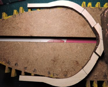
With all the whole frames done, that is all the frames with floors that crossed the keel i now have to build the half frames at the stern and bow. The foot of these frames sit against the deadwood.

to start i glued the floor and first frame pieces together

laser frame25.jpglaser frame26.jpg


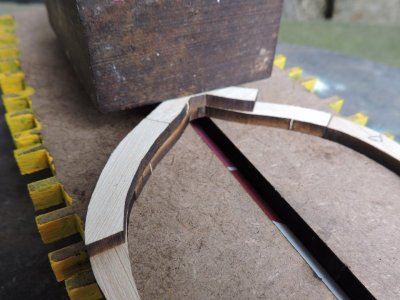
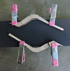
the first frame i built freehand by clamping the lower section to a flat surface the i took the top section and also clamped it down making sure i butt the two pieces together. Once the two pieces are where i want them i glued the top piece in place. This top piece joins the two lower pieces.

laser frame27.jpg
 
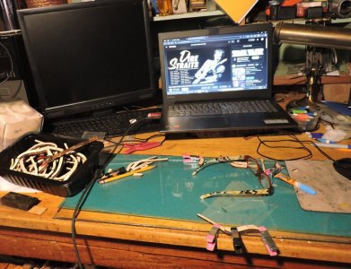
building frames from laser cut parts requires only a set of headphones, clamps and glue no mess no fuss. This is about the building process and not all the wood milling. It is relaxing with Dire Straits playing i can build frame right on my desk.

in part model ship building is more than the model it is a state of mind a moment of Zen.

laser frame29.jpg
 
Last edited:
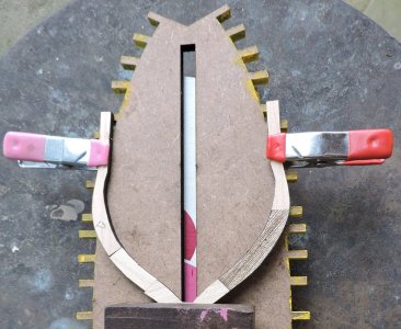
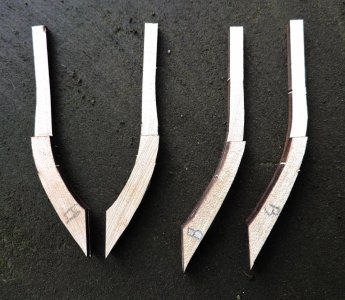
good Saturday morning, this last week i finished building all the frames. From frame 1 to 27 it did not matter how the frames were built but frames at the bow A B C and D have to be built as a pair. Building the frames like the ones on the right will not work in the hull. The frames have to be built as a right and left pair.

laser frame30.jpg
 
With all the frames built it is time to turn attention to the keel and hull.

jig1.jpg


You may of noticed some kits will advertise their kit is "historically accurate" using that term is stretching it to the limits. The model built from the kit may in a general way look historical but far from being built like a historic wooden ship.
Wooden ship kits use a building methos called plank on bulkhead and that is in no way and not how wooden ships were built. There are exceptions and a few kits are plank on frame much closer to "historically accurate" but the majority out there are plank on bulkhead.
You can build kit after kit and you may hone your building skills, but bulkhead kits are not teaching you how a wooden ship was built or how to build a model of a wooden ship. The two styles of building are not even in the same universe.

jig2.jpgjig3.jpg

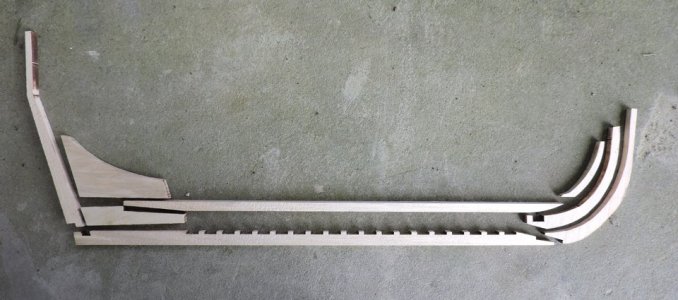
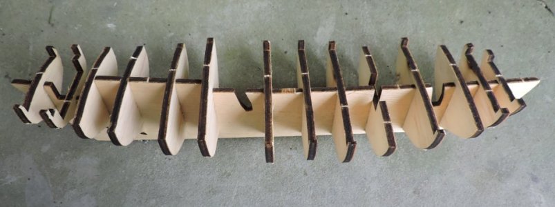
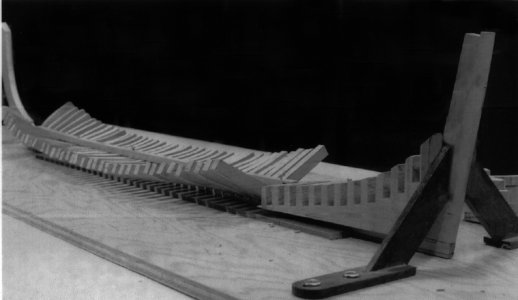
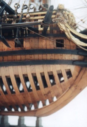
A historically accurately built model of a ship starts out looking like this. Building a framed hull presents a number of challenges you would not have to deal with when building a plank on bulkhead kit. Kits are by nature designed for a hobby builder and made as simple as possible to hopefully succeed in finishing the model. A plank on bulkhead model builder does not have to know how a wood hull is built just follow the kits instructions should result in a ship's hull.

jig4.jpg
 
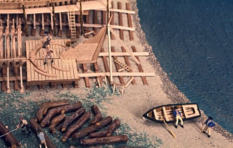
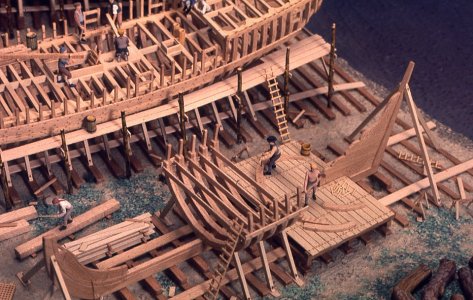
First problem for the model shipwright is setting up the frames. In real ship building a framing stage was built where the frames were assembled and lifted into place

jig20.jpg

Once in place they were secured using batons where the frames were attached on to the other and supports to prevent them from leaning.

jig19.jpg

as a model shipwright the first problem is standing up the frames and holding them in place. to do this you can use square blocks to hold the frames square to the keel and straight up.

jig5.jpgjig6.jpg

one thing the square blocks will not do is to level the frames from side to side, they can lean right or left. to level the frame you would measure up from the surface to the top of the frame making sure it measures the same.


jig7.jpgjig8.jpg
 
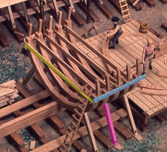
in actual ship building a free form type of jig system is being used with cross batons, batons from frame to frame and supports that anchor the structure to the ground. As a model shipwright we do not have to follow the same system, but we do have to find a way to hold all the framing in place.

jig21.jpg
 
DISCLAIMER: My humble opinion

only a very few possess an artistic talent, gift, or ability of building ships from scratch. Most of the on coming communities that want to even get into this wonderful hobby, first have to learn the ships nautical terms and body plans which takes a long time unless a person is gifted in such areas. Instead of the encouragement of Hahn, I see a disconnect and discouragement from common folk that want to pursue the hobby. To me, his doctrine and philosophy is too strict and almost borders a line of arrogance against those that are unable to understand the complexities of scratch building. Which there again has a propensity of weeding out those that want to pursue the hobby. In other words, unless a person can’t build a ship from scratch they are not worthy in his eyes.
However, I also applaud anyone willing to take on the task to educate the rest of us on how to scratch building.
I stand on both sides of this discussion. I see the attraction in using a kit to get to a finished, displayable model as quickly as possible. I also have a puritan streak that says if you are making a 'model' of a ship, it should be the real thing in miniature.

I noticed the books by Underhill in the photo's - reading those altered my own view from 'kits' to 'models'
Coincidentally, I received a piece by Chris Schwarz earlier today. If you substitute 'Kits' for 'jigs' and 'planking / deck fittings / rigging' for the other woodworking terms it seems to sum up my feelings.
It reads

"Tool catalogs are great at explaining how jigs can solve your joinery problems. Can’t cut perfect miters/dovetails/spline joints? This jig does it with ease. You will be a master in no time. Promise.
Here’s what I learned: Cutting miters is a skill. Learning to set up, use and then remember again how to use a jig to cut miters is also a skill. Both skills take about the same amount of time to learn.
Yes, there are some jigs that can speed you along if you need to do something 134 times in a week (such as making a dovetailed drawer). But those jigs are rare and are usually needed only by production or industrial shops.
Most woodworking skills are mastered after a few tries, and then you will forget about owning the jig."


- Yes, you can assemble kits, but you get a good deal more satisfaction from making a model ship. But then, you may be on a path that wants the complex rigging on show in a case, no matter that there are hundreds like it elsewhere.

At the end of the day, it is solely about what brings most pleasure to YOU, and whatever you feel is the right way to get there.


J
 
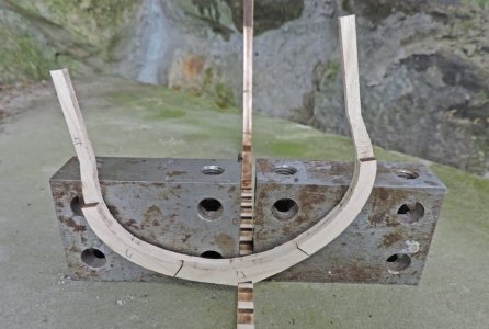
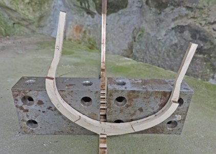
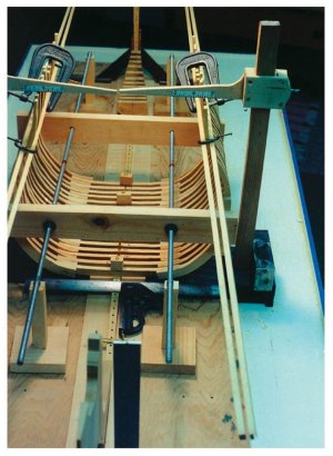
as an engineer and a model ship builder Harold Hahn first had to recognize the problem of placing frames exactly where they go and hold them there while the hull is being built then figure out a solution to the problem. His building jig idea did not just fall out of the sky, The idea of building a framed hull in a jig came from Bob Bruckshaw. Bob was experimenting with ways to build admiralty models and using various ways to jig up the hull.

jig9.jpg

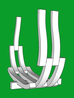
The jig idea was the way to go but it needed a redesign to be used for anyone wanting to try their first plank on frame model. The problem with bob's jigging was the framing it required the builder to set all the floors on the keel


floors.jpg

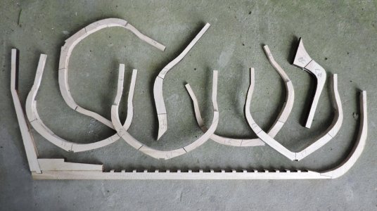
the frames were built up by placing the futtocks between the floor heads.


A45.jpg


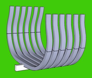
for a jig to work for a model builder the frames had to be complete as a unit

frameshape1D.jpgsingle frames2.jpg
 
Last edited:
I stand on both sides of this discussion. I see the attraction in using a kit to get to a finished, displayable model as quickly as possible. I also have a puritan streak that says if you are making a 'model' of a ship, it should be the real thing in miniature.

outside this "school for model ship building" there are a few topics that rage on about kit vs scratch or are kits nothing but a paint by number version of real scale modeling of a ship, the historically minded vs hey i just want a pretty looking model, are scratch builders more knowledgeable and skilled compared to a hobby version of the art
it is interesting to explore different philosophies on the subject and debate the pros and cons.
Here in this topic it is about the "how" to do it and what the master class of model shipwrights did and how they approached the various problems facing a model shipwright.

way back before i was employed as a commercial artist i took courses in industrial arts and i remember the machine shop of jigging up a job was a big deal. In my personal model building i do not use a milling machine to do joinery it is all done by hand.
 
Back
Top