- Joined
- Dec 1, 2016
- Messages
- 6,378
- Points
- 728

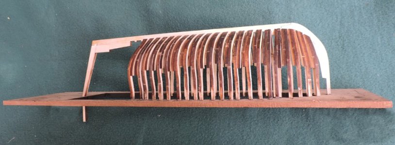
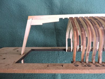
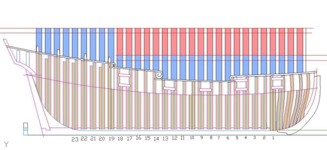
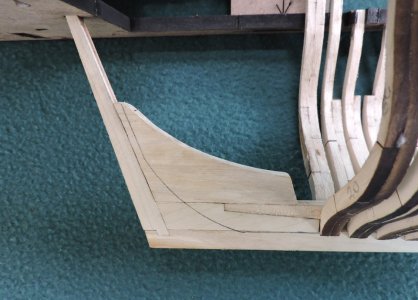
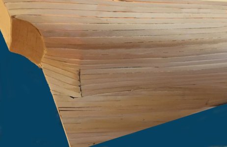
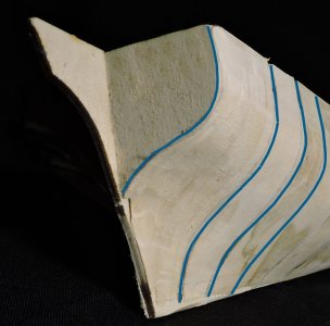
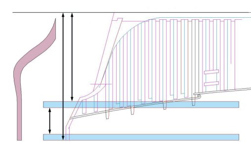
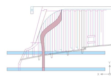
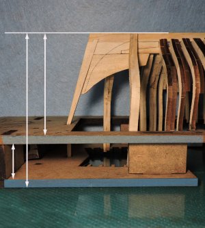
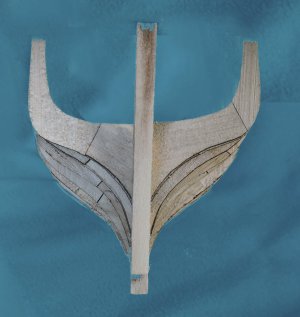
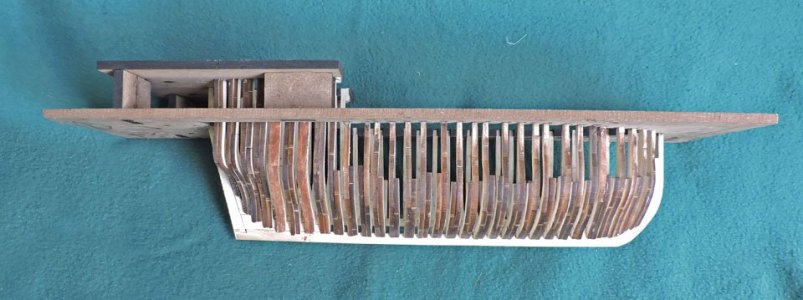
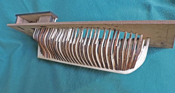
The cant frames in the bow are next and they are not like the rest of the frames. The only reference point is the top line where they sit in the jig. the bottom line is the rabbit line and as you can see the cant frames rise up on the stem. The middle line shows the rise of the deck at the bow.
Plank on bulkhead builders will skip the bow construction and installing cant frames. A solid block is glued in at the bow and shaped to fit the hull.
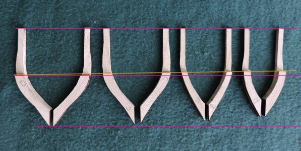
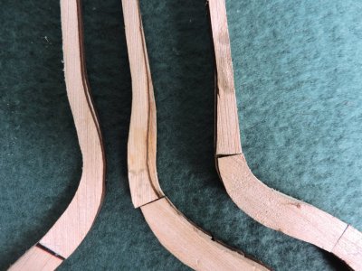
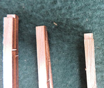
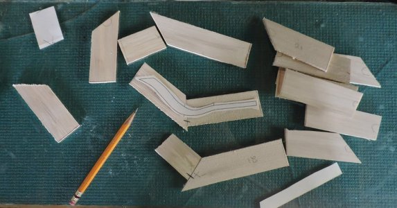
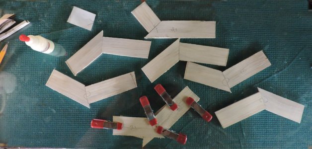
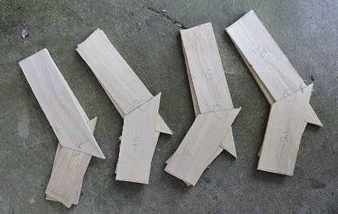
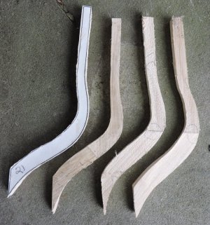
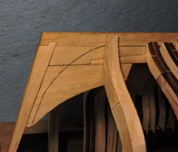
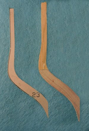
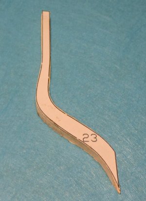
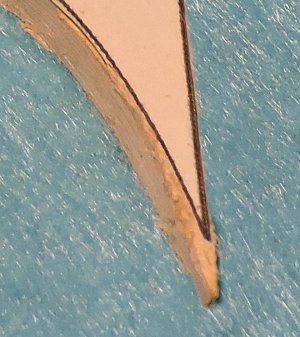
Cant frames are named because they are canted forward to lessen the amount of material that has to be taken off the face of the frames to create a bevel. The foot of the cant frames have an angle.
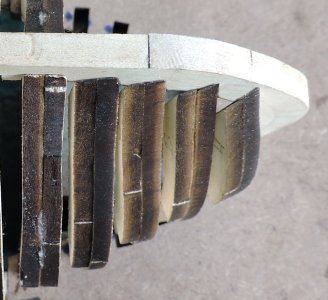
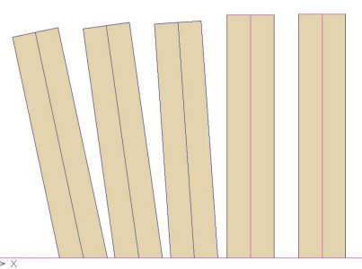
The angle can be taken off the drawings
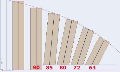
How you can get a perfect angle is up to you. But when you get the angle of the foot right the frame will fall right in place.
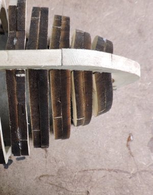
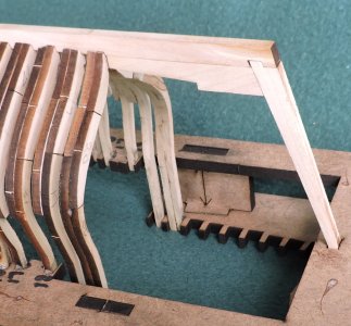
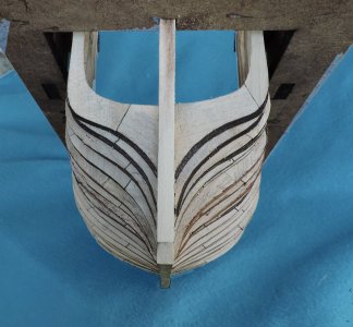
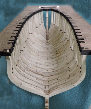
the foot of the cant frames will follow the stem and rabbit line, you should have a nice sweet arc on the stem.
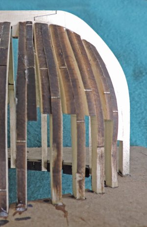
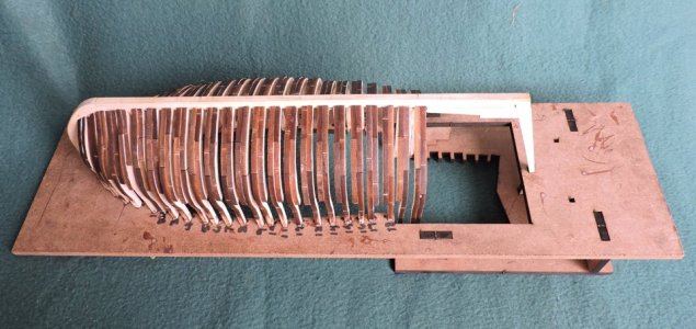
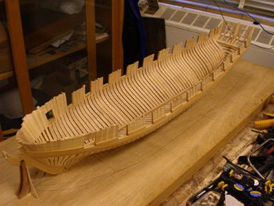
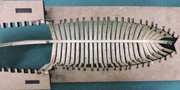
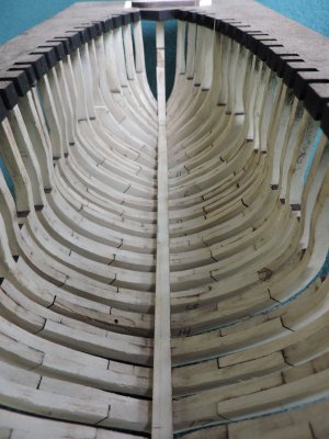
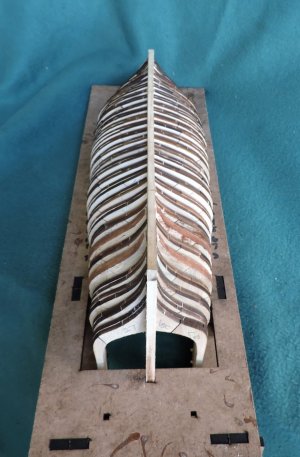
looking down the hull all the frames form a straight line along the keel and arch at the stem. The term used by master shipwrights and model shipwrights is to ever so sweet curves of a hull. you can see that starting to take shape. Inside and out.
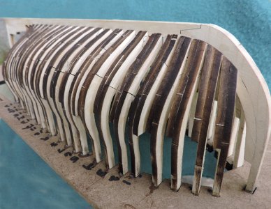
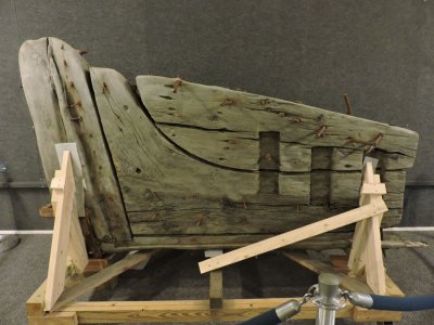
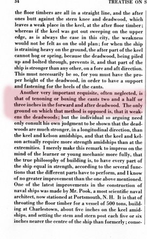
That space at the bow between the first cant frame and the stem is where the ? go anyone know what goes there?
Plank on bulkhead builders will skip the bow construction and installing cant frames. A solid block is glued in at the bow and shaped to fit the hull.

Cant frames are named because they are canted forward to lessen the amount of material that has to be taken off the face of the frames to create a bevel. The foot of the cant frames have an angle.

The angle can be taken off the drawings

How you can get a perfect angle is up to you. But when you get the angle of the foot right the frame will fall right in place.

the foot of the cant frames will follow the stem and rabbit line, you should have a nice sweet arc on the stem.

looking down the hull all the frames form a straight line along the keel and arch at the stem. The term used by master shipwrights and model shipwrights is to ever so sweet curves of a hull. you can see that starting to take shape. Inside and out.

That space at the bow between the first cant frame and the stem is where the ? go anyone know what goes there?

Last edited:


