- Joined
- Dec 1, 2016
- Messages
- 6,379
- Points
- 728

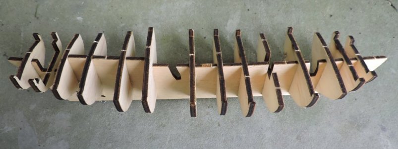
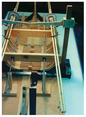
As a result of reading Davis’s book I attempted, unsuccessfully to build a POF model. Hahn’s method offered something not described in Davis’s book; a way to align the frames. My next attempt using Hahn’s method produced a model that I am happy with. I believe that you judged it at one of the contests held at the Inland Seas Museum.
i did judge all the shows back then so most likely i did judge your model. there were. actually it was a panel of judges.
Since you knew Hahn well, I have a question that you can perhaps answer. To what extent was he influenced by Davis’s work and book? Was his method originally a way to improve on Davis’s work by adding the upside down building jig? If so it made building POF models practical for many of us.
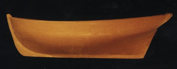
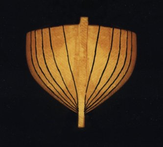
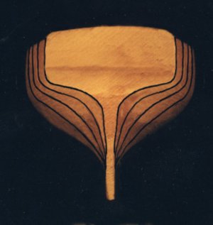
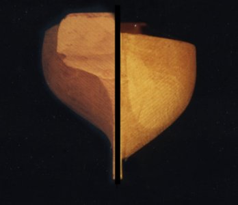
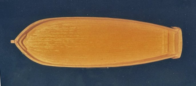
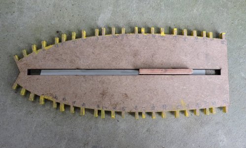
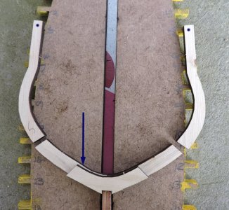
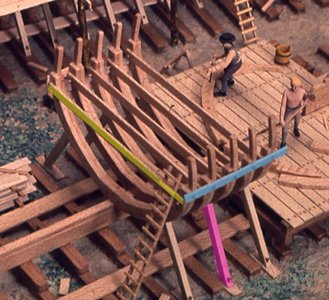
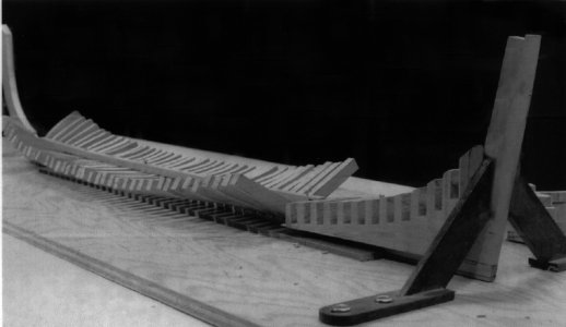
it was Robert Bruckshaw that influenced Harold building in a jig. Bob used a floating sort of jig, i will see if i have a picture of one of his hulls under construction. Bob built models on private contracts and for the Smithsonian he had no interest in the hobby end, where Harold got into writing articles and books, drawing modeling plans and designing a method for hobby builders to succeed in plank on frame models. So Harold redesigned Bob's building method.
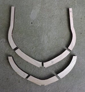
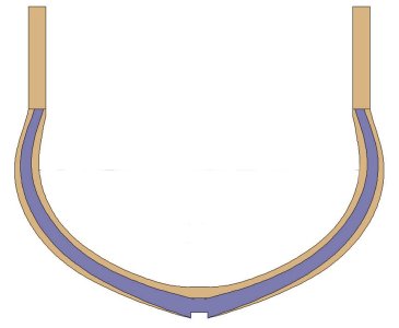
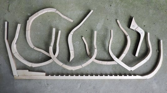
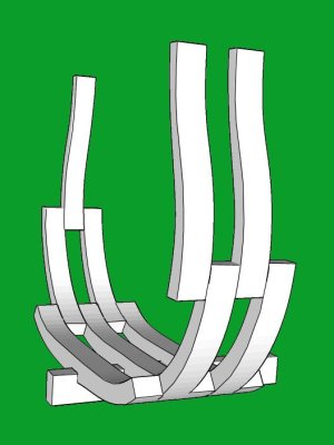
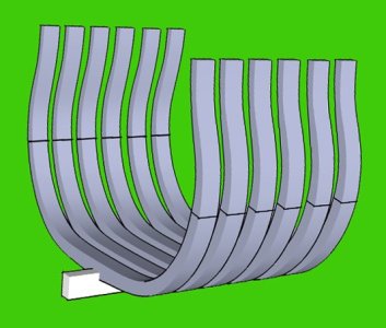
Relative to criticism directed at him for the double sistered frames: In the early 1970’s I don’t remember any American ship modelers publishing any research about actual Eighteenth Century framing practes. Later on, people began to criticize Davis’s reconstruction of the Brig Lexington including the double sistered frames. This spilled over to Hahn’s work as well.
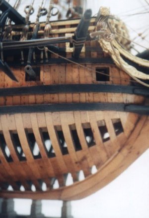
back in the early 1970s there was little research and archaeological information in the hobby world of model ship building. It was all pretty much a mystery as to how ships were built. At an NRG conference Portia Takakjian introduced her model of the Essex which used the British system of framing of a sistered frame and single filler frames. When asked about why she chose that system of framing her answer was "because i like it" Later on when the Essex was published by Anatomy of the ship series the framing was changes to historically correct all sistered frames. The British version of framing caught on as a fad and somehow connected with the Admiralty models. At the time building English ship was all the rage and pretty mush still is. It is rare to find American built ships besides the Constitution and Rattlesnake. My guess English ships just looked pretty American ship were more practical they were ship of war and that was that, little gingerbread was added. You can see in the model Expo Confederacy using English framing a left over from an early fad and not realistic.
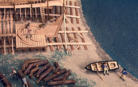
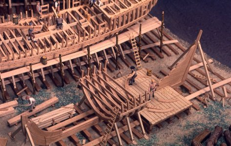
When the academic world of archaeology and the hobby of model shipbuilding began to overlap there was a flow of information. War of 1812 ship wrecks on the great lakes hum in the Great lakes all the ships even the British ones were all sistered framing.
Now we know better so we can build better and closer historical models.


