Thanks Dave! Your instructions are perfect as well as timely since I’m working on my Le Rochefort deck planking at the moment.
-

Win a Free Custom Engraved Brass Coin!!!
As a way to introduce our brass coins to the community, we will raffle off a free coin during the month of August. Follow link ABOVE for instructions for entering.
-

PRE-ORDER SHIPS IN SCALE TODAY!
The beloved Ships in Scale Magazine is back and charting a new course for 2026!
Discover new skills, new techniques, and new inspirations in every issue.
NOTE THAT OUR FIRST ISSUE WILL BE JAN/FEB 2026
You are using an out of date browser. It may not display this or other websites correctly.
You should upgrade or use an alternative browser.
You should upgrade or use an alternative browser.
School for Shipmodel Building School for model ship building
- Thread starter Dave Stevens (Lumberyard)
- Start date
- Watchers 72
great job Dave
- Joined
- Dec 1, 2016
- Messages
- 6,390
- Points
- 728

Today i will continue with the deck construction moving forward i am starting with the deck beam aft of the windlass posts.
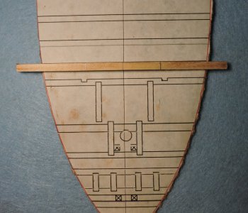
the two beams where the windlass post sit have notches in them. The posts for the windlass take a lot of stress and are held in place. Some vessels hold the post in place between carlings like this along with a heavy plank, The post is locked in place and can not move side to side or fore and aft.
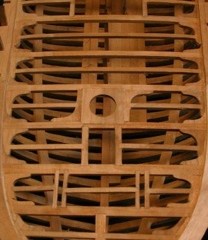
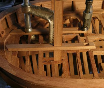
The Hawke the beams are too close together so the beams are notched to hold the windlass posts from moving.

the two beams where the windlass post sit have notches in them. The posts for the windlass take a lot of stress and are held in place. Some vessels hold the post in place between carlings like this along with a heavy plank, The post is locked in place and can not move side to side or fore and aft.


The Hawke the beams are too close together so the beams are notched to hold the windlass posts from moving.
- Joined
- Dec 1, 2016
- Messages
- 6,390
- Points
- 728

shop talk
first is to make marks where the notches go. I prefer using a knife to make marks rather than a pencil it is more accurate
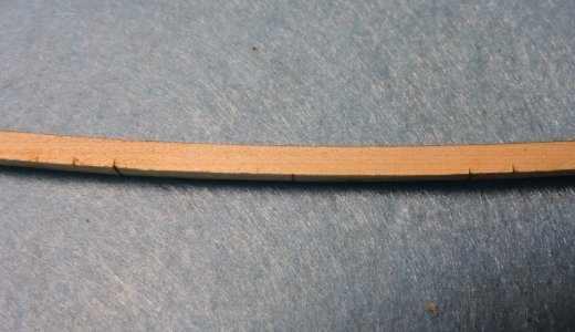
Over time using a knife i have cut a shallow stop cut then tried to make the cuts for notches and time and time again over ran the stop cut and sliced off a corner or split the wood past the stop cut. What i do to avoid a slip is in cut a V to the stop cut. I am cutting downward so there is little chance of slipping past the stop cut.
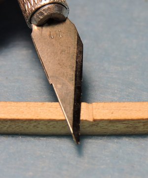
Now it is just a matter of removing the material at the center between the V cuts, shaving a little at a time and deepening the stop cut as needed.
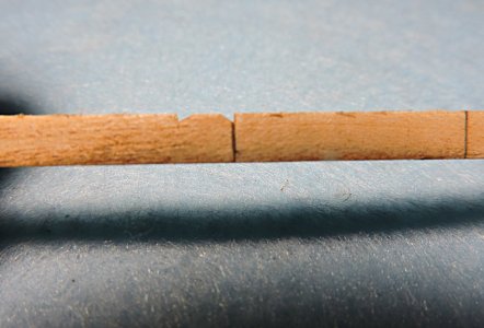
once i finish one beam i line up another and repeat the notches
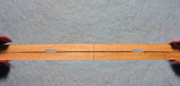
The notches do not have to be too deep just enough to hold the windless posts in place
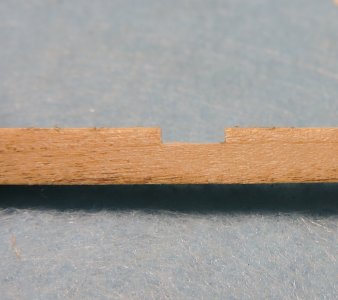
first is to make marks where the notches go. I prefer using a knife to make marks rather than a pencil it is more accurate

Over time using a knife i have cut a shallow stop cut then tried to make the cuts for notches and time and time again over ran the stop cut and sliced off a corner or split the wood past the stop cut. What i do to avoid a slip is in cut a V to the stop cut. I am cutting downward so there is little chance of slipping past the stop cut.

Now it is just a matter of removing the material at the center between the V cuts, shaving a little at a time and deepening the stop cut as needed.

once i finish one beam i line up another and repeat the notches

The notches do not have to be too deep just enough to hold the windless posts in place

- Joined
- Dec 1, 2016
- Messages
- 6,390
- Points
- 728

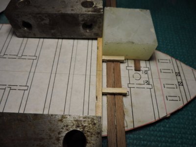
Moving forward there are 2 carlings to frame in the grating. The carlings are smaller than the beams and the beams have an arch so the pieces of wood are holding up the carlings so they are even with the top of the beams. Once again i stress making sure your work is always square. I am using a square piece of Onix which was once part of a chess board.
For the mast partners they are usually in two pieces but i am cutting it in one piece.
first i drill holes for the masts
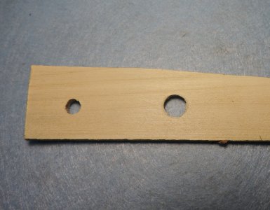
it is easier to layout the piece around the hole rather than trying to drill a hole in the center of a small piece
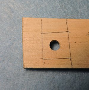
after the partner is cut out i need two notches in the corners for posts.
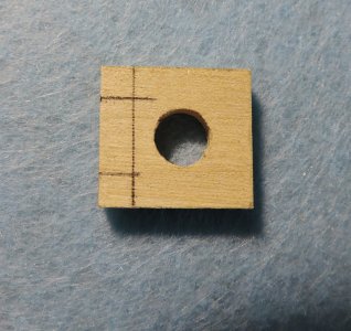
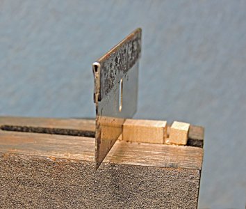
watch which way the grain is running i clamped the partner in the vice and with a razor saw cut along the vice.
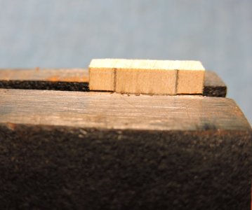
The grain is running up and down so it is easy to use a razor blade and split the notch
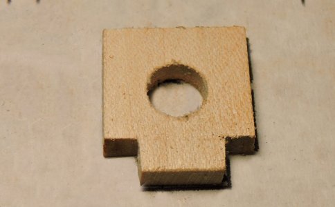

For the mast partners they are usually in two pieces but i am cutting it in one piece.
first i drill holes for the masts

it is easier to layout the piece around the hole rather than trying to drill a hole in the center of a small piece

after the partner is cut out i need two notches in the corners for posts.

watch which way the grain is running i clamped the partner in the vice and with a razor saw cut along the vice.

The grain is running up and down so it is easy to use a razor blade and split the notch


- Joined
- Dec 1, 2016
- Messages
- 6,390
- Points
- 728

Back in the classroom
Sometimes when you are researching you hit a snag. Your sources do not agree with one another or down right contradict one another. Howard Chapell in his philosophy stresses historical accuracy. When you build a model with errors you're putting that forward and way to often builders that come after you or use your work as a reference the error continues.
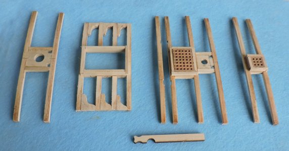
here are the finished sections of the deck next i will trim down the beams and fit each section into the hull. Then add lodging knees and tie everything together.
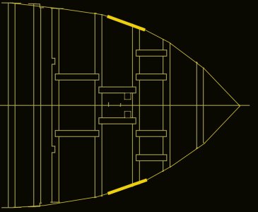
Notice the section to the far right and the grating location. here is the original deck layout it is showing two gratings. What happened?
The wider yellow section is the location of the gun port.
When your drawing in 2D sometimes it is difficult to see in 3D and how everything relates to one another. While building the deck and checking my work to the hull i noticed something seems to be "not right" I over laid a top view of a 4 pound cannon and carriage on the deck and sure enough there is not enough room to fit a cannon it would sit on top of the grating.
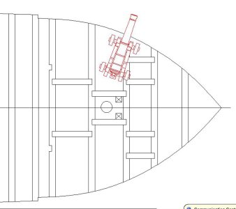
You cannot move the grating for or aft so i reduced the size but that still did not give enough room for a cannon. Next i tried to move the gratings closer to center but that did not work either.
going back to the original source i took a look at the drawings in Chapelle's book. Yes it does show two gratings in the deck layout. The gun port tinted green and the gratings tinted red are i conflict with each other.
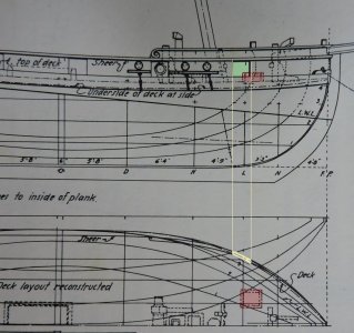
I noticed the deck layout is not from an original admiralty drawing it is a reconstruction. Either Chapelle made a mistake or someone under him made an error.
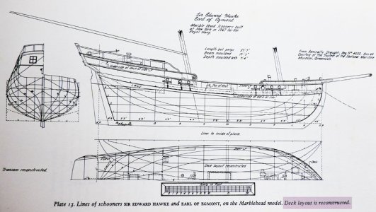
The next thing i did was to check the model built by Harold Hahn thinking maybe i got something wrong and maybe a cannon does fit there.
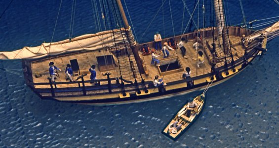
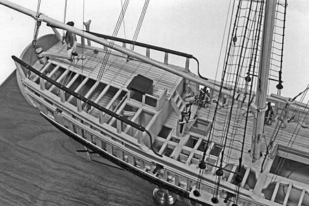
Zooming in at the bow there is the forward gun port tinted green. Harold Hahn notices the problem so what he did was to include the gun ports at the bow but notice he did not put a cannon on the model. I know Harold did visit Chapelle at his home and they became friends over the years. maybe Harold did not want to point out errors to his friend, so he just let it pass.
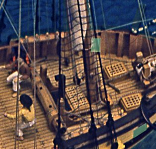
Now it is my problem! and my solution is if you notice there is a grating drawn on the original admiralty plan so it is definitely there but why two? my solution was to put one grating in the center now you have the grating like shown on the original plan and room for cannons although a tight fit.
so there you have it and why Chapelle stressed accuracy even though he himself was not immune to errors.
Sometimes when you are researching you hit a snag. Your sources do not agree with one another or down right contradict one another. Howard Chapell in his philosophy stresses historical accuracy. When you build a model with errors you're putting that forward and way to often builders that come after you or use your work as a reference the error continues.

here are the finished sections of the deck next i will trim down the beams and fit each section into the hull. Then add lodging knees and tie everything together.
Notice the section to the far right and the grating location. here is the original deck layout it is showing two gratings. What happened?
The wider yellow section is the location of the gun port.

When your drawing in 2D sometimes it is difficult to see in 3D and how everything relates to one another. While building the deck and checking my work to the hull i noticed something seems to be "not right" I over laid a top view of a 4 pound cannon and carriage on the deck and sure enough there is not enough room to fit a cannon it would sit on top of the grating.

You cannot move the grating for or aft so i reduced the size but that still did not give enough room for a cannon. Next i tried to move the gratings closer to center but that did not work either.
going back to the original source i took a look at the drawings in Chapelle's book. Yes it does show two gratings in the deck layout. The gun port tinted green and the gratings tinted red are i conflict with each other.

I noticed the deck layout is not from an original admiralty drawing it is a reconstruction. Either Chapelle made a mistake or someone under him made an error.

The next thing i did was to check the model built by Harold Hahn thinking maybe i got something wrong and maybe a cannon does fit there.

Zooming in at the bow there is the forward gun port tinted green. Harold Hahn notices the problem so what he did was to include the gun ports at the bow but notice he did not put a cannon on the model. I know Harold did visit Chapelle at his home and they became friends over the years. maybe Harold did not want to point out errors to his friend, so he just let it pass.

Now it is my problem! and my solution is if you notice there is a grating drawn on the original admiralty plan so it is definitely there but why two? my solution was to put one grating in the center now you have the grating like shown on the original plan and room for cannons although a tight fit.
so there you have it and why Chapelle stressed accuracy even though he himself was not immune to errors.
- Joined
- Dec 1, 2016
- Messages
- 6,390
- Points
- 728

With the sections built it is time to assemble the deck. All the knees were hand made so they will vary in size which means the overall length of the deck may vary. You are now building the deck to fit the hull rather than following the drawings. to begin i built the bow section because it locates the forward grating, the mast and the windlass. The last section is the end of the main deck and where the cabin starts.
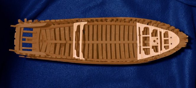
Working forward the section with the mast is added
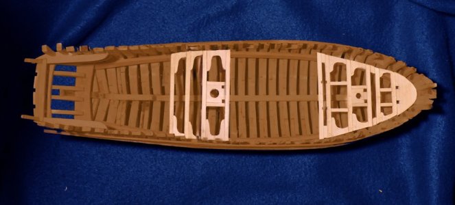
then the section with the main hatch is put into place. This section can be moved fore or aft a little bit to accommodate the last two beams.
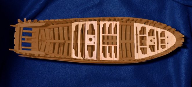
This is the finished main deck
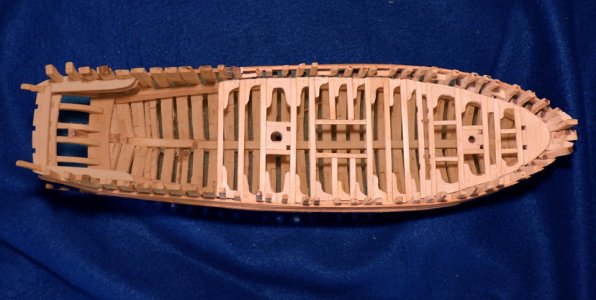

Working forward the section with the mast is added

then the section with the main hatch is put into place. This section can be moved fore or aft a little bit to accommodate the last two beams.

This is the finished main deck

- Joined
- Dec 1, 2016
- Messages
- 6,390
- Points
- 728

decks can be very complex in their structure, here we have a deck from an English frigate. the dark parts are the main deck beams between the beams are the ledges in yellow, the red parts are carlings, the blue are the lodging knees and finally the green are the hanging knees.
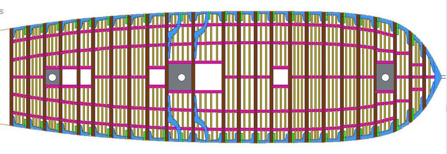
to do the joinery on such a deck would be a massive job the ends of the carlings have a lap joint into the main beams and the ledges have a lap joint into the carlings and in such a deck there is a lot of joinery.
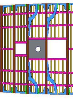
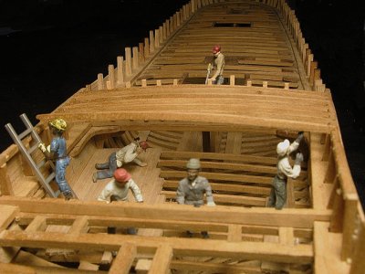
There would be no need to take the time and effort to build such a deck if you plan on planking the deck, unless you build a model to show off the joinery and only plank sections.
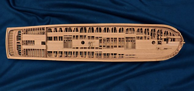

to do the joinery on such a deck would be a massive job the ends of the carlings have a lap joint into the main beams and the ledges have a lap joint into the carlings and in such a deck there is a lot of joinery.

There would be no need to take the time and effort to build such a deck if you plan on planking the deck, unless you build a model to show off the joinery and only plank sections.

- Joined
- Dec 1, 2016
- Messages
- 6,390
- Points
- 728

- Joined
- Dec 1, 2016
- Messages
- 6,390
- Points
- 728

Very, very interesting, Dave. Your knowledge as a Model Shipwright is impeccable. You make it easier for us in our infancy of building model ships to understand the concept. I read your transcripts with interest, and this time I had the idea of removing the deck to expose the Breadfruit Pot Holders on the Bounty and other things, for which you gave me the go-ahead to do that.
I remember Uwek had a log on a ship he did in two parts, which he could lift to expose the lower decks. and then lower down to not see the join.
Actually, this hobby is about time, and if you can think outside the square or circle, wow, the sky is the limit! We have the time to do that. Sometimes, we need that prompting from knowledge from the net and the SOS.
Just a parting thought. We can scale many things when we scale for a model, but can we scale wood as in grain? No, we cannot, but if we could, how tough would it be? Cheers
Last edited:
- Joined
- Dec 1, 2016
- Messages
- 6,390
- Points
- 728

The Waterways
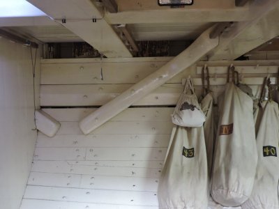
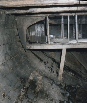
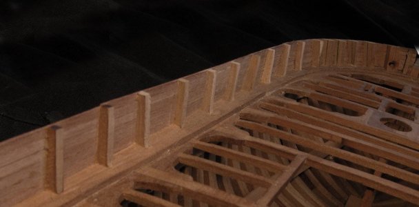
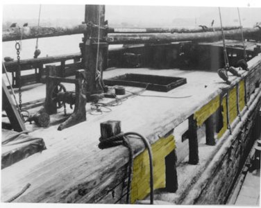
Once the main deck is built it is time to add the waterways. There are two different types of waterways depending on the type of vessel and how the bulwarks are constructed. Let's take a look at two waterways. in this photo the waterway is a heavy timber that sits on the ends of the deck beams and butts to the inside of the bulwarks.
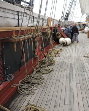
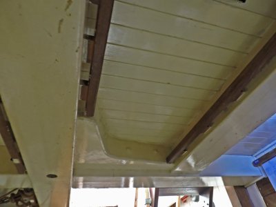
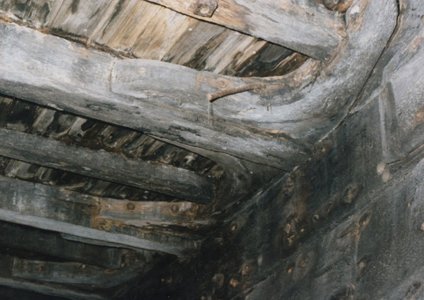
This waterway sits on the deck beams but unlike the top example it extends around the top timbers and to the outer edge of the hull
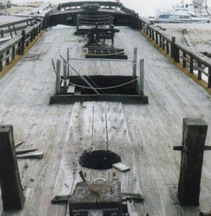
the waterway has notches cut for the timbers and a molding runs along the outer edge
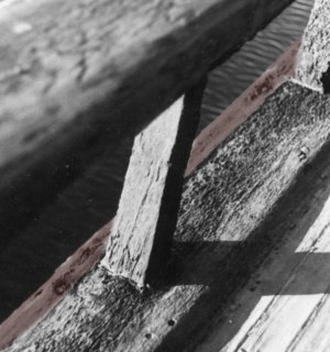
the bulwark planking sits on the waterway and covers the seam between the outer edge of the waterway and the molding
Once the main deck is built it is time to add the waterways. There are two different types of waterways depending on the type of vessel and how the bulwarks are constructed. Let's take a look at two waterways. in this photo the waterway is a heavy timber that sits on the ends of the deck beams and butts to the inside of the bulwarks.

This waterway sits on the deck beams but unlike the top example it extends around the top timbers and to the outer edge of the hull

the waterway has notches cut for the timbers and a molding runs along the outer edge

the bulwark planking sits on the waterway and covers the seam between the outer edge of the waterway and the molding

Last edited:
- Joined
- Dec 1, 2016
- Messages
- 6,390
- Points
- 728

- Joined
- Dec 1, 2016
- Messages
- 6,390
- Points
- 728

- Joined
- Dec 1, 2016
- Messages
- 6,390
- Points
- 728

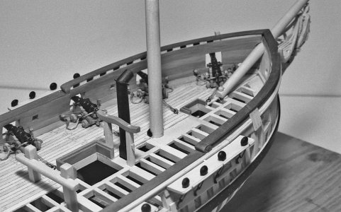
The Sir Edward Hawke has the bulwarks planked inside and out so the waterway is a simple timber that runs along the bulwark.
The bend around the bow had to be soaked in water and clamped in place until dry.
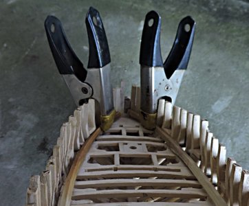
if you plan on keeping the deck open then a sanding along the ends of the deck beans to level out the beams and knees might be needed. But if your going to add decking then a slight space between the waterway and deck structure will be covered.
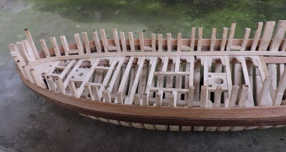
The bend around the bow had to be soaked in water and clamped in place until dry.

if you plan on keeping the deck open then a sanding along the ends of the deck beans to level out the beams and knees might be needed. But if your going to add decking then a slight space between the waterway and deck structure will be covered.

- Joined
- Dec 1, 2016
- Messages
- 6,390
- Points
- 728

- Joined
- Dec 1, 2016
- Messages
- 6,390
- Points
- 728

Start with a print of the deck and fit it to the hull
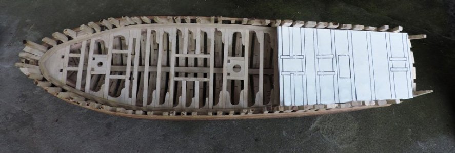

like the main deck i will start where the deck begins and where it will end then filling in between. When building you have to keep in mind that tiny little creeping so if you start and move in just one direction you may end a little long or short.
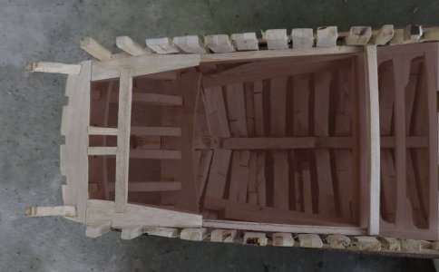


like the main deck i will start where the deck begins and where it will end then filling in between. When building you have to keep in mind that tiny little creeping so if you start and move in just one direction you may end a little long or short.

- Joined
- Dec 1, 2016
- Messages
- 6,390
- Points
- 728

When you are building from scratch or no preset directions mistakes will happen and i found one when i went to install the deck clamp. Back when i finished framing the hull and added timbers between the last frame and the stern it came to my attention i did not slant the cross timber to the deck, i put it in level.
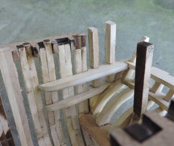
One nice thing about having to do something over you have the experience of the first time you did it so the second or third time you know what to do. So i ripped out the timbering, Now you can see the slant of the deck clamp.

It was easy and the rebuilt went smoothly
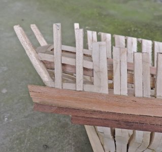
The deck clamp runs under the cross timber


One nice thing about having to do something over you have the experience of the first time you did it so the second or third time you know what to do. So i ripped out the timbering, Now you can see the slant of the deck clamp.

It was easy and the rebuilt went smoothly

The deck clamp runs under the cross timber

- Joined
- Dec 1, 2016
- Messages
- 6,390
- Points
- 728

the last deck bean notches into the cross timber

Two carlings are installed to frame in the area for the rudder. To make sure they line up with the stern timbers i clamped a piece of wood to the stern timber and slid the carling against the piece of wood.

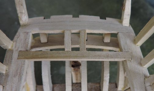
When you look down you can see through the carlings and stern timbers.
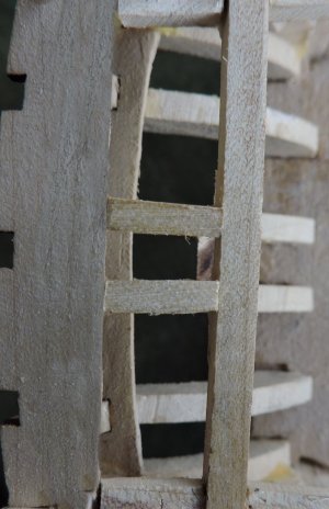

Two carlings are installed to frame in the area for the rudder. To make sure they line up with the stern timbers i clamped a piece of wood to the stern timber and slid the carling against the piece of wood.


When you look down you can see through the carlings and stern timbers.

- Joined
- Dec 1, 2016
- Messages
- 6,390
- Points
- 728


