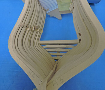
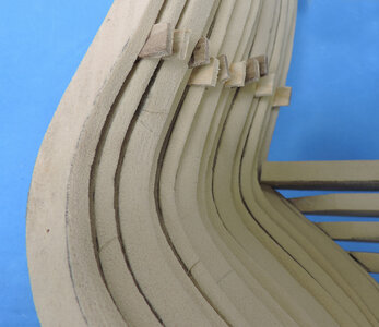
Scratch building the Alfred Stern

i used super glue to assemble the hull which made it easy to take apart with acetone. A couple drops and the glue gets soft and gummy.
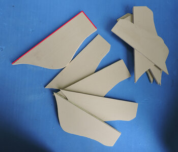
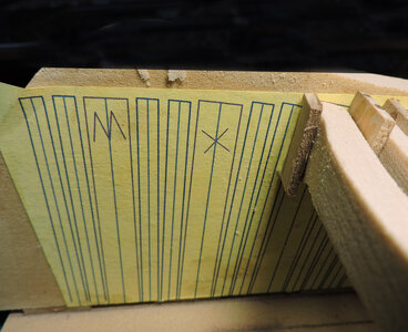
I took each frame and painted the side with bright day glo green, next i laid them on my scanner and scanned them. Now i have an accurate template to bring back into CAD and trace them and make corrections on the inside of the frames.


redo3.jpg
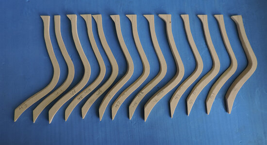
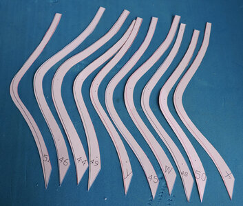
The new frame drawings were printed out with the bevel lines.
redo4.jpg
 
Hello Dave,
nice work so far. I had Mr Shanks make me window frames and decorations for my Alfred in 1/64 scale on his laser cutter.

yes i remember

i sent Mike all my CAD files on the Alfred stern, the group was looking into the idea of a stern kit at that time. Actually, this build is a spinoff of the original idea.
 
There are two approaches to building a framed hull one i already discussed which is to build it with enough extra material on the frames to shape the hull. Another approach is to build and shape every frame then install it into the build. The second method will require accurate frame drawings to start with. the second method requires enough sandpaper to keep sanding until the hull looks good.
There are pro and cons to each method, if your finishing each frame inside and out you do not have to try sanding inside the hull. Sanding a rough hull requires the hull to be secure in a jig or added spacers between frames. sanding can get a little brutal and cracking a frame does happen.
Hahn plans are pretty darn accurate but would still give yourself a little extra when cutting out frames. Usually there is no problem with all the whole frames the problems seem to be at the bow and stern where frames take a beveling.

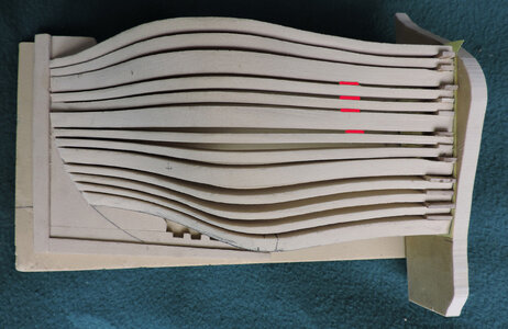
Once i had a new and improved set of frame drawings based off the original sanded hull i made blanks for the outside of the hull. i did the blanks because i wanted to maintain each frame's location at the center and at the jig which are the red lines.

redo9.jpg

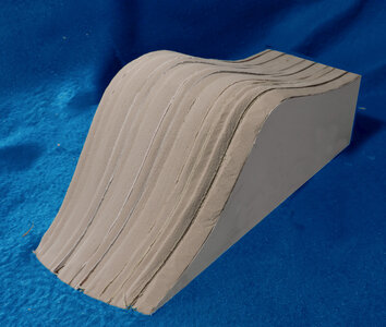
i could not go any further with the original hull without sanding through the hull in places. So i stacked the blanks using the center edge and jig edge and touched up the hull.

redo7.jpg

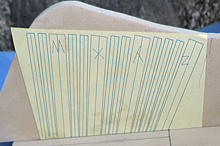
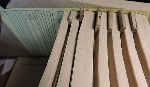
Next step i glued the paper patterns to the blank lining up at the outer edge. and finished off the frames with the bevels.

redo8.jpg
 
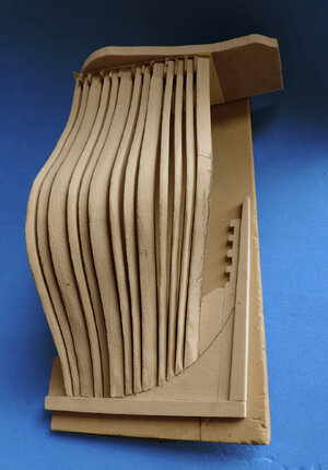
round 2 of the hull i am not rebuilding the frames. This is now a design project and not an actual building of a model. I cut the frames in one piece using HDU

High density urethane foam board also known as HDU board is used for hand-carved signs as well as CNC-machining. Styling Board (SB) has a fine surface structure and lends itself to both manual and mechanical processing. Precision Board Plus™ High Density Urethane (PBLT) is a “closed cell” rigid polyurethane product made specifically for applications of up to 200°F continuous exposure. High Density Urethane is available in a wide range of sheet sizes, thicknesses, and densities. It can be cut or bonded into a variety of shapes for final machining or shaping.

working with HDU is so nice but messy when you cut or sand it you get a gritty sand that has so much static it sticks to everything. Even though HDU is high density when you cut is down into small parts it is prone to break. When you finish a part you can coat it with a resin or polyurethane which soaks in and gives you a hard shell finish.
 
now to test my new and improved frame drawings, will they produce a nice hull? lets see

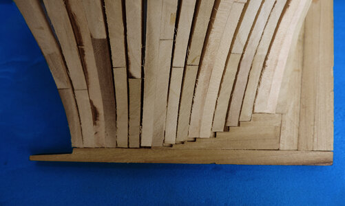
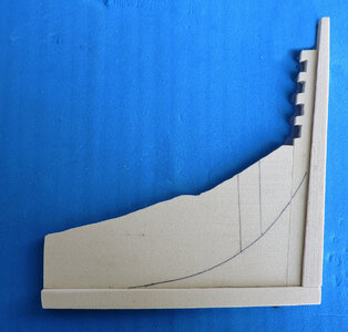
First off Harold used a arched rising line at the foot of the frames, someone told me you got to step the deadwood inorder for it to be true to the actual building methods. That might be true but not in every case or all the time. but i did it anyway.
The results were not as expected. nope! that is adding way to much problems, the steps are exact width of a frame plus the space between the frames. If you are not dead on perfect with the width of the framing the foot will override the step and hang over to the next. It is like fitting a jig saw puzzle.


redo5.jpg

I went back to Harolds original using an arc for the rising line. It's the old KIS keep it simple i do not want to introduce any more problems into the build. This has to be something a first time semi scratch builder can do.

redo6.jpg
 
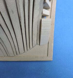
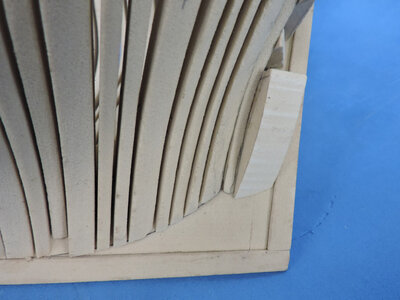
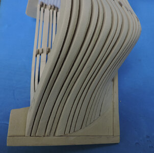
An arc at the foot of the frames looks so much better and cleaner. Notice the two thinner frames in the center where the space got wider. This happens because the frames are thin to begin with and there is only a point at the jig and at the foot holding the frames in place. If you are slightly off with the angle on the foot it will affect the space between the frames. Or the wood will naturally decide to shape itself. In order to prevent the spacing going out of wack use spacers lower down the frame. These spacers will be covered with the wales and upper planking.

redo17.jpg
 
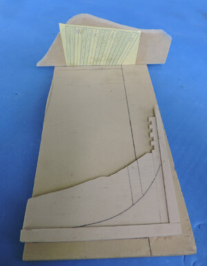
setting up my testing jig i took a scrap piece of board and drew 2 lines at a 90 degree one is the baseline at the bottom of the keel the other is to set up the jig location. i drew the location of frame Z on the deadwood

redo11.jpg

set my jig layout with frame Z on the line. I also took a measurement from the baseline to the location of the jig that distance is very important because it sets the location of each frame when it sits in the jig.


redo10.jpg
 
it seems no matter what that creeping dimension persist
using spacers and building off frame Z within a few frames i am already lost the space and i am into the next frame


redo15.jpg

six frames to go and trying to keep the framing as close as i can. But! because this is a stern model with an open end it is not critical where the last frame ends up. as long as you hit the horizontal line which you see where the frames have bee placed. Hitting that line makes sure the frame line up.

redo16.jpg
 
After weeks of building, going back to the drawing board well drawing screen in modern times with CAD, building and ripping apart what i did and rebuilding. Checking and rechecking, making parts 3 times in some cased

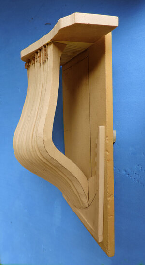
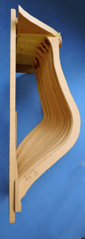
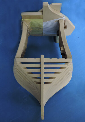
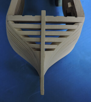
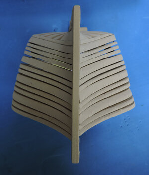
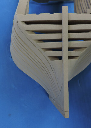
and the final results a perfect hull inside and out.

redo12.jpgredo13.jpgredo14.jpg


the project is far from done at least i know the frame drawings are right so now i can break them down and create a laser cutting file. for the project i am offsetting the cut by .0040 a fat 1/32 inside and out and that is the total tolerance you have to work with. Any first time semi scratch builder this is a precision build which gives you a taste of scratch building. You working with frame blanks there is no bevel that is something you have to do, the angle of the frames have a narrow + or-. the good news is if you mess up all the frame parts are replaceable.
 
now to test my new and improved frame drawings, will they produce a nice hull? lets see

First off Harold used a arched rising line at the foot of the frames, someone told me you got to step the deadwood inorder for it to be true to the actual building methods. That might be true but not in every case or all the time. but i did it anyway.
The results were not as expected. nope! that is adding way to much problems, the steps are exact width of a frame plus the space between the frames. If you are not dead on perfect with the width of the framing the foot will override the step and hang over to the next. It is like fitting a jig saw puzzle.


View attachment 454880

I went back to Harolds original using an arc for the rising line. It's the old KIS keep it simple i do not want to introduce any more problems into the build. This has to be something a first time semi scratch builder can do.

View attachment 454881
Dave, the stepped method would seem the most practical in full scale to me. These timbers weigh a lot. So stepped, the deadwood would absorb all of the weight of the frame. In Hahn's variation using a straight bearing line it would seem to me that the frames fore would absorb the weight of the after frames. To me it looks as if it would want to slide push fore. I assume there is a guide or recess that the frame would cradle in. Certainly a treenails would not be robust enough.

However on a model the Hahn acc is hansome and clean.
 
Dave, the stepped method would seem the most practical in full scale to me. These timbers weigh a lot. So stepped, the deadwood would absorb all of the weight of the frame. In Hahn's variation using a straight bearing line it would seem to me that the frames fore would absorb the weight of the after frames. To me it looks as if it would want to slide push fore. I assume there is a guide or recess that the frame would cradle in. Certainly a treenails would not be robust enough.

However on a model the Hahn arc is hansome and clean.


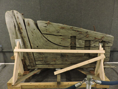
the practice of "boxing" was used on the foot of 1/2 frames. a shallow box was cut into the deadwood and the foot of the frame sat on a ledge at the bottom of the box. then an iron rod ran through both frames and deadwood with a clench ring pulling the frames to the deadwood
Exactly how the Alfred was built we will never know. but for this model project i am simplifying the build. the deadwood was made up of many parts but i am using one piece/ As a semi-scratch build the builder has options.


boxing.jpg
 
once i had one side looking good and patterns for the frames i did the other side so now i am back to where i was originally, but this time with a nice looking hull.

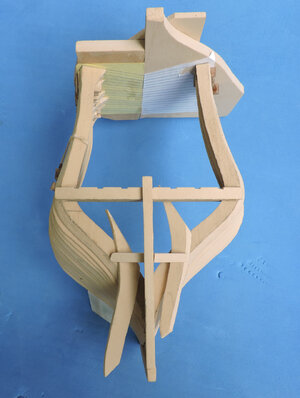
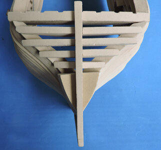
Adding the transom pieces is something i had to think about.. In order to get the exact same cant and location of the last frame Z to match the one i had in place. I decided to put the wing transom in so i can locate the foot of the frame on the deadwood and rest frame Z against the end of the transom. I also need the height so i put the fashion timber against frame Z. Well, that was a bad ides because there is no way to install the lower transoms between the stern post and frame Z. So i removed the fashion timbers. This gave me enough room to slip in the lower transoms. You can see in the photo i am using the fashion timbers so i can shape the transoms to fit.
It might have been better to install all the transom pieces first then add frame Z

redo18.jpg
 
i roughed in the transom pieces and glued a block at the base of frame Z which i will shape to fit. Now that all the transom pieces are in place i will give the hull a final sanding and blend the ends of the transoms into the fashion timber. .
It was not possible to install the transoms with frame Z and the stern post in place. I had the options of either taking out the stern post, removing frame Z or cutting the transom pieces and installing them in two pieces. If this were an actual finer wood model being built i would have ripped out the stern post and built the transoms out from frame Z. But in this case the model is just a prototype and built from dense foam board. All i needed to know was if the blanks for shaping the transoms would work.
This is what makes this project a semi-scratch build and not a kit. Pieces like the transoms have to be hand shaped from a rough blank
and fit to the model. They are not a finished piece you just glue in.


redo19.jpgredo20.jpgredo21.jpg

redo22.jpg
 
i am back to where i started with model 2.0
talking to model builders over the years i get feedback about trying semi scratch building or scratch building or POF building. Seems the reason is a fear of messing up or not being able to work through a project that has no step-by-step instructions. Sometimes it is about all that work and i ended up with garbage which is a little discouraging. I look at it as a trial run a learning experience.
Scroll up to the last post and take a look at the rough built, here is what a little sanding does

redo23.jpg
 
satisfied with the new 2.0 model i can now move forward.
The transom pieces began as a rough blank and i shaped them to fit into the hull structure leaving myself enough material to refine them once they are set in place.

redo25.jpg

look down or up from the bottom the transoms take a fan shape from the lowest to the wing transom. You can see the shape by the darker areas.

redo24.jpg

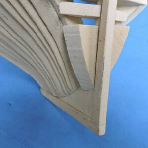
next i refined the rising line of the foot of the frames. I started out stepping the frames on the deadwood but that did not work out for me. Stepping the frames required exact sizing of the frames and exact fitting of the frames on their steps. So i went with the smooth curve.

redo26.jpg
 
i precut the bevels, some builders prefer cutting the bevels before installing the frames. It does make it easier to finish the inside bevel when the frames are nor installed, but you have to be very accurate when cutting the bevels. I always installed a rough frame blank and shaped the hull as one unit. This time i tried the bevel first method and it worked pretty well but i was not exact enough. when the bevels are precut, you have to be very accurate when building the hull.
I did not sand the bevels to the line on the drawings i fell short of the line giving myself a little wiggle room with building the hull. Once all the frames are in place then i gave the hull a final sanding and shaping. i am happy with the results and no need to start hull 3.0.

redo27.jpg
 
When scratch or semi scratch building there is no turning the page in the instructions to see what is next. You have to pre plan your moves and that is part of the fun with building it your way. I see the need to stabilize the frames to keep them in place where they belong and maintain an equal spacing.
To do that i am going to install the deck clamps on the inside. Before i can do that i have the spacers in the way, so i have to sand them down.
Yup mistake to add to the list. The model is using a machinable dense foam board, and the spacers are wood. Well the difference in hardness between the two make it difficult to sand the spacers and frames at once.
This would have been no problem if the model was built of wood,

redo28.jpgredo29.jpg
 
it has been a little over a month since my last post on this project. Other things have kept me busy like 2 big trees in the yard came down in a storm, you don't realize the size of the limbs and cleanup when such large trees are on the ground. Then Ev and i decided to refinish the oak hardwood floor in our living room. The floor took quite a beating over the last 35 years with the wood burning stove bring in firewood, muddy and wet boots, pets, kids and foot traffic took its toll. It is a big room and taking everything out of the room wall to wall and the sanding and finishing to a smooth high gloss takes time. We have to wait 3 days for the finish to fully cure than it is moving back in.
Then working with a 3D printer to produce printed cannons for our Hahn ships timbering sets.

DSCN9985.jpg
 
Back
Top