Signet's Bonhomme Richard Cross Section [COMPLETED BUILD]

Joined
Nov 17, 2021
Messages
1,029
Points
408

Location
Columbia, SC
Yeah, another one. There are already so many builds, of such high quality, that I'm sure you're thinking we don't need another one. But I'm hoping that my build might provide some interesting discussion, and the build will definitely be from a professional non-perfectionist viewpoint. Besides, Uwe asked me to do it. :)

I won't go through opening the kit, as there are so many other threads with better coverage. I'll try to cover some things I haven't seen, or perhaps that I've done differently. Please excuse my clumsy start and initial photos; I'm taking pictures with my phone, and am not sure how they will turn out or how this will read, so today's posts are practice, and hopefully they will later improve.

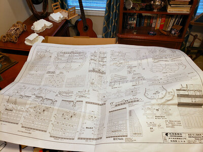
The first thing I did after receiving the kit (full pear version, with interior, barrels, and carved belfrey and railing) for Christmas was to go to Staples. There is just one large sheet of plans, 34" x 48", and of course folded:
20211230_140601.jpg
This makes it a bit hard to work with, especially without ruining the original plans, so I had Staples make 2 full-size copies ($6 each), and also a file of the image in PDF format. I cut up one of the large copies, including small details that related to each other in each separate "sheet", but most are copies of the larger cross sections and views I will be relating to. I am able to easily work with the smaller sheets, and protect them with glass or wax paper during work, so as not to have to keep making copies.

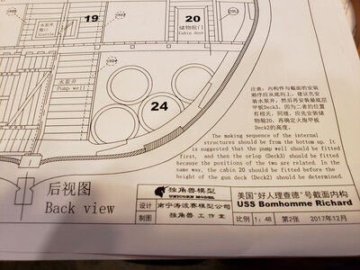
A topic of conversation here about this kit is the lack of English instructions. It appears that Unicorn has heard our pleas, as there is a fair amount of English translations currently included with the kit. If you zoom in on these plans, you will see that area titles and some notes have been translated from Chinese to English. I used Google Translate to view translations to confirm their validity (included translations in general are better than Googles) and make any notes or changes. The 30+ page instruction manual is all photos and pictures, but they have included 6-pages which list Chinese and English for each step:

20211230_141323.jpg
While not elaborate, they are definitely helpful. If anyone building this kit does not have the translations, please let me know and I'll post a copy that you can print.

The optional Interior Kit has instructions on 8 A4 sheets (8.25" x 11.5") and includes both Chinese and English:
20211230_141249.jpg

I decided to start the kit by doing a complete frame, as I knew there would be a lot more to come, and I wanted to practice, get ideas, and maybe get more ideas from you. I chose Frame 2 to start, as 1) It wasn't as visible as 1 or 9, which show at the outside, nor did it contain any cuts for gun ports (more on that later). While the quality of the stripwood is fantastic, as is the quality of the wood with the laser-cut parts, I'm not as happy with the laser-cut parts. First, they're hard to "punch" out, requiring cuts with a blade in the uncut areas. Someone mentioned using a "sturdy" blade, so I used a retractable utility knife. It didn't do badly, but I still had to cut both sides, and I found the long blade would sometimes cut into areas I didn't want. I'm going to try a shorter, thinner scalpel blade to see if it does better. One of my problems is that cataract surgery has left my "good" eye no longer able to see at close distances, so I have to switch to strong reading glasses (3.0, 4.5 and 6.0) to see close stuff. I /think/ I'm cutting right without them, then see my errors with them.

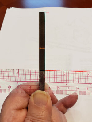
The second disappointment is that the laser cuts are not perpendicular to the surface. Although they appear much larger, I've measured them at 2-6 degrees, probably averaging midway. This results in a bad fit without sanding, a lot of sanding for a good fit, an pieces end up a bit narrower than they should be when done on both sides. Neptune, in his excellent build log, mentioned to keep the same face of the wood upright when building the frames; I suspect the angle, which he also mentions, is the reason for this. I tried switching around trying for a better fir without sanding as much, but that didn't help. These pics give you an idea of the angle (ruler is shoved in tight to a cut joint):
20211229_123723.jpg
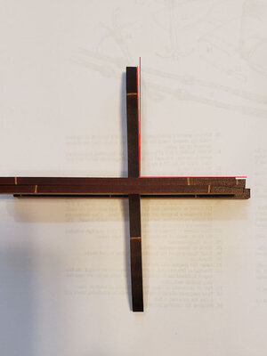
The notch where the keel fits into the lower frame (floor?) notches is tight, so it ends up at an angle too:
20211229_124023.jpg
I have to file the openings somewhat larger so the frames will fit the keel when at a right angle.

As much for practice photography and testing, here are a pile of frames before sanding the joining areas:
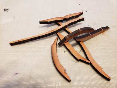
20211229_140407.jpg
And afterwards:
20211229_140438.jpg
I sanded them at right angles to the outline surface, just taking off the char in this area now. It's easy to sand too much off and not notice it. This applies to the end and "notched" areas, especially. I found that when I had a mating pair about right, I could hold them an "rock" them back and forth, to see if one end was a bit too long, and if so, sand it down to fit better.

For my first frame assembly I used clothespins to secure the joints. I tried the plastic clamps, but the frame thickness was too small. Also, I tried Elmer's Glue-All, but it didn't dry fast enough to suit me, so switched to Titebond Quick & Thick, which I'm happy with so far.
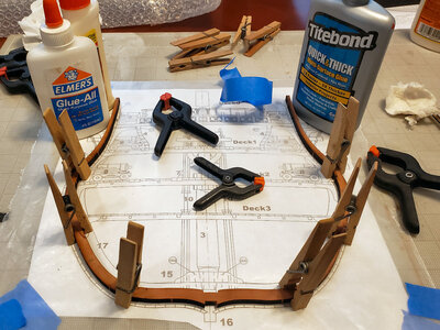
20211229_152649.jpg
This clamping method didn't work out that well for me, though. When doing the second half, I found that the clamping force of the clothespins on the sloped scarf cause the pieces to slide and separate, and I didn't see that until picking the piece of some time later. I used water and slowly separated the pieces on that half, cleaned it up and redid it. This time I placed clothespins like this:
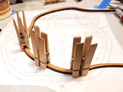
20211229_170830.jpg
This clamped each clamping edge on part of each piece, keeping it snug, but not causing the slide. I've ordered 20 2" metal clamps which I hope to use in the future with better results.

I wasn't sure whether to build up a second half-frame (the two are fastened together) and glue it over the first, or build up the second on top of the first. In the end I chose the second method, feeling I'd keep alignment better, and I think it did:
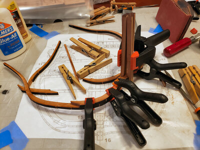
20211229_214520.jpg
I used two of the keep pieces clamped in place to keep the two floors in alignment. Then added, and clamped, added and clamped.
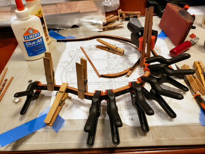
20211229_214909.jpg

After drying overnight, I sanded the inner and outer char off. Alignment wasn't as good as I'd hoped, and the section is slightly thinner than it should be because of this. I hope my other frames, using a different clamping system, will be better. I've also glued the first four parts of the keel together with the bevels for planking. I found this easier to assemble two pieces at a time, true up, then continue.
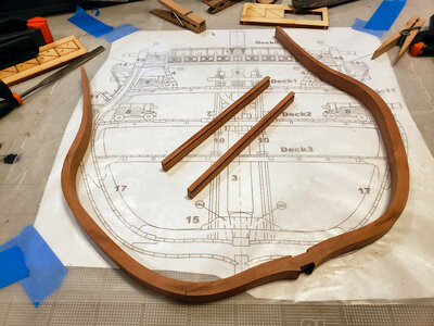
20211230_114306.jpg

Speaking of the keel, I've come to my first question (I'm hoping I will get more from you during this thread than I will show you): Shouldn't there be a FALSE KEEL on the model? I'm not that familiar with the construction of French ships, but thought this was pretty much standard: a replaceable timber to protect the keel and its joints. I can easily add a piece to the bottom, of course, but didn't want to if it shouldn't be there.

My second question refers to the jig that is included for frame alignment:
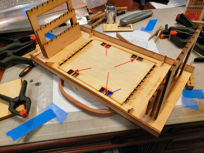
20211230_114320.jpg
I've followed its use in the instructions, but wonder: Why is the large, mostly-rectangular section of the bottom plate left loose to move? I thought at first it was to be removed, but it isn't. The little "bridges", shown in 4 locations with the red arrows, are what attach this section to the rest of the bottom plate. Allowing it to move slightly vertically. The frames don't fit that tight, and I have NO idea why this was done this way. Does anyone know? Also, the 8 rectangular cutouts on the section, one pointed to by the blue arrow, seem to have a specific outline and maybe a purpose? Again, I have no idea.

Okay, that's my first installment. In the future, I will try to include more/better content, less pictures and more "unique" stuff. We will see. PLEASE don't hesitate to point out things I've done wrong, suggest alternate ways of doing things, etc. In short, help make me a better modeler, and this a better model.
 
Last edited:
I wanted to ask everyone's opinion on a particular portion of this build, and thought if people skimmed through the above obvious stuff, they might read this. ;-)

Concerning the gun ports, the method they've recommended is to complete the frame & hull structure, with stiffeners, then use the templates to draw the outlines and cut them. Well, I've had a rough time making such ports on other models. So, I wonder that since the exact height of each gunport is shown on the cross section drawings for each deck, and again shown in the side view drawing for each port, if I couldn't make the cuts in the frames themselves BEFORE assembly? It would be so easy to trace the outline on the appropriate frames. Some would be cut only partway through the double frame (making this VERY easy to do this way). Others would cut the frame apart entirely, but they would have non-cut frame portions beside them, and I would think by using the cross stiffeners, they could be attached in the appropriate alignment with the ones on either side.

This method would allow neat, square cuts to be done more easily, and I would think, more accurately.
 
Signet, looks like you are off to a great start. I had a lot of fun with this kit but there are some frustrating parts as you are discovering. The alignment of the frames with the drawings is absolutely critical. I didn't pay enough attention early in my build and it bit me. As you see, the small slots in the base of the jig labeled R1-9 eventually receive the tops of the ribs as you place the ribs in the jig. As the 9 ribs are not identical and taper to one end of the hull, this compounds any issues with the ribs not being wide enough or too wide. Really watch that rib alignment with the plans as you put the pieces together. I also discovered for the first time something that most folks on this site already know and that is that laser cuts, especially through thicker wood, are not perpendicular. Not only does this impact the building of each rib but caused me issues when I placed the ribs on the keel, had to gently sand down the slot in the base of the ribs to get perpendicularity of the ribs to the keel. Was a painful lesson. I can't remember what the holes in the base of the jig are for but will go through my stuff and see if any bells are rung. I think you will really enjoy this kit and will try to think of some more issues that I encountered. Gun port height/location are good in the jig but I really had to adjust most locations very slightly as my ribs didn't fit perfectly into the jig (reasons above). Spent a lot of time taking measurements off the drawings to get as accurate as I could.
 
Thanks for responding, Adiefenbach. I notice on the one frame I've done that at the tops, on both sides, one of the frames is slightly longer than the other. I used the notch on the floors to center, but if any joint is sanded more than required, or not as tight, that will vary the height of the sides. I've looked ahead and know that the sides are cut off at the top, so figured the height didn't matter much. But - as the frames are inserted with the tops down into the jig, and will hit the table below it, turns out that length is REALLY critical, because differing heights will change the keel height. I'm surprised they measure everything off these uneven tops, instead of the keel height, which HAS to be constant. Not sure how that will work out.
 
I wanted to ask everyone's opinion on a particular portion of this build, and thought if people skimmed through the above obvious stuff, they might read this. ;-)

Concerning the gun ports, the method they've recommended is to complete the frame & hull structure, with stiffeners, then use the templates to draw the outlines and cut them. Well, I've had a rough time making such ports on other models. So, I wonder that since the exact height of each gunport is shown on the cross section drawings for each deck, and again shown in the side view drawing for each port, if I couldn't make the cuts in the frames themselves BEFORE assembly? It would be so easy to trace the outline on the appropriate frames. Some would be cut only partway through the double frame (making this VERY easy to do this way). Others would cut the frame apart entirely, but they would have non-cut frame portions beside them, and I would think by using the cross stiffeners, they could be attached in the appropriate alignment with the ones on either side.

This method would allow neat, square cuts to be done more easily, and I would think, more accurately.
Hi Signet.
One thing to be mindful of ( and this is probably stating the obvious), the angle of the cut will be parallel to the future deck angle at that location and not the edge of the frame). Also if you make the cuts now, the bracing may need to be temporary. I had a hard time working out where the planking was to be located. However:
1. Your plans have English subtitles
2. I build for the enjoyment and not necessarily for perfect accuracy (so many models and life is short )
3. My model ended up slightly different on the left vs the right side - the planking locations are off by some 3-4mm. Still, it looks fine.
I would be happy to answer any questions.
 
I took all measurements from the bottom up vice from the top down. I also counted the hull planks from the keel on up as a good constant baseline. The plans are very accurate that way. After measuring 18 ways from Sunday, I found that cutting out the gun ports, having pre-drilled holes around the perimeter, wasn't that bad. Used a flat end scroll saw blade by hand for most of the cutting. Have to make sure that the gun port sills remain horizontal from outside to inside.
 
Hi Signet.
One thing to be mindful of ( and this is probably stating the obvious), the angle of the cut will be parallel to the future deck angle at that location and not the edge of the frame). Also if you make the cuts now, the bracing may need to be temporary. I had a hard time working out where the planking was to be located. However:
1. Your plans have English subtitles
2. I build for the enjoyment and not necessarily for perfect accuracy (so many models and life is short )
3. My model ended up slightly different on the left vs the right side - the planking locations are off by some 3-4mm. Still, it looks fine.
I would be happy to answer any questions.
Thanks, Oldpaperone. Yeah, I would either make the port openings parallel to the deck, or simply straight across from one side of the ship to the other (like taking a knife, drill or file from one side to the other). It may require additional bracing, which I gather is no problem, unless it is in an area I want the internal structure to be shown.
I agree about the enjoyment part. If I wanted perfect accuracy, I'd have to simply buy it from one of you guys instead of making my own. Like my HMS Victory cross section, I trust it won't be perfect, it /will/ be interesting, and I'll be proud of the result.
 
I took all measurements from the bottom up vice from the top down. I also counted the hull planks from the keel on up as a good constant baseline. The plans are very accurate that way. After measuring 18 ways from Sunday, I found that cutting out the gun ports, having pre-drilled holes around the perimeter, wasn't that bad. Used a flat end scroll saw blade by hand for most of the cutting. Have to make sure that the gun port sills remain horizontal from outside to inside.
Yeah, it makes more sense to me to work dimensions from the keel up. I'll just keep this all in mind and be able to shift methods as necessary, I think.

And cutting the port openings in the frames before assembly is my idea of being sure they're horizontal. But I'll have to see. Thanks for your response.
 
Last edited:
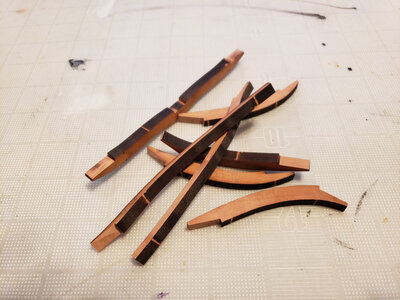
Today I found a shortcut method for cutting out the laser-cut ribs, and a note or caution concerning them. Please excuse me if this is obvious to everyone. This is my first laser-cut kit, at least in this thickness of material, and the caution was not at all obvious to me when reading the instructions or watching all the videos.

Concerning cutting the ribs (technically cutting or breaking the four uncut areas that hold most pieces in place, which IMHO are thicker than they should be), I first tried a utility knife, which wasn't too bad but cut too long cut and could intrude on the actual piece. I then used a regular Xacto blade and also tried a narrow scalpel blade. I wasn't that happy with them either: too much force applied to a breakable blade had me concerned. I even used a very small screwdriver to wedge not-quite-cut pieces apart, resulting in that screwdriver being jammed under my fingernail!

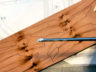
In an AHA moment, I got out my wood carving chisels, and found the sharpest, smallest straight chisel I had, which is just over 1/8" wide:
20211231_125509.jpg
(Sorry for the fuzzy picture. Holding everything in position with one hand, while focusing and taking the photo with the other, is a skill I haven't mastered yet.)

I take the untapered side of the chisel toward the piece to be removed, and on a solid surface give a light tap with a nylon head hammer:
20211231_125530.jpg
Depending on force, sometimes that will break/cut through the joint entirely, and often separate the pieces a bit. I do all the cuts facing me (straight side), then turn the piece and do all those facing the other way. Depending on your hammering force, some pieces will pop or fall out, others will stick but are obviously cut, and those that remain can be cut from the other side of the sheet after turning it over. I've also tried just bumping the chisel with my palm, but found I can do it more easily and consistently with the chisel.

The note or caution concerns which side of the rib sheets to use, the unprinted side, or the side that has laser numbers and such on. It's fairly obvious it's easies to use the printed side, and before cutting out the parts, number them according to the sheet's markings. Neptune mentioned you should keep all numbered sides facing you when assembling a single rib, and that's good advice, although I have found that after sanding and squaring the joints, the pieces are identical from side to side. But there's another reason to get into that habit.

On the one rib I assembled, I simply chose the face of the first rib that looked the best (no defects, best joints, etc.) and faced it down (outside), then assembled the second rib to it in place. I could have also made the second separate and attached them, but I felt I could align them better the first way (not sure it worked - I need better clamps). If I'd done it the second way, I'd have chosen the best side of the second rib to face outwards, and glued them.

I lucked out with Rib #2. Actually, I had a pretty good chance. It turns out that ribs 8 and 9 have some sections additionally marked with lines which I'm sure are there for tapering the ribs combination, along the length of the ship. Here's a view of the additional lines, identified with arrows:
20211231_131420.jpg

When I first saw these lines, I honestly thought I was seeing double (I mentioned my close vision problems). But as probably all of you know, these light lines are for chamfering or tapering the ribs to provide for the curve in the hull and planking. Because of this, I feel one has to first assemble, in the above case, the 91 rib, with numbers and faint lines facing up, sand off the chamfers to the lines shown, then assemble the 92 rib over top of it, also sanding the marked chamfers.

Until now, I thought I knew what I was doing and describing, but I do see a problem that I'm hoping someone can help with: If the 91 rib is assembled, then the 92 rib assembled and mounted to it, I would expect the inside of both ribs to coincide, but on the outside, I would think the 92 rib would align with the faint line indicating the chamfer, and not to the edge of the wood. That way, they can both be chamfered, and still the inside will line up. However, from what I can see the 92 rib is NOT narrower at this point than the 91 rib (nor is it the other way around).

To make this clear (I hope) I'll show 3 ways I think the combining and sanding of frames 8 and 9 could be:
Frame Joint.jpg

The joint marked Should Be? is the way I thought it would and should be: The inner, square part of the frames would coincide, making planking and such fir along a fairly straight line (I say fairly as there is a taper toward the stern). For this to occur, the frame toward the stern must be somewhat narrower than the one forward it it. But it doesn't seem like that's they way they're made in the kit.

It seems to me that if you assemble the kit as shown, with the inner sides even with one another, the two bevels, if sanded beforehand, would not result in a continuous curve or line, but a sawtooth patter, which is certainly not correct.

If the pieces were offset somewhat, as shown in the bottom diagram, the outside line would be continuous, but then the inside wouldn't.

Maybe this is a case where you'd better off noting the chamfer marks: Just assemble the frames even with one another, then sand after assembly to approximate the "Should Be" example? If anyone has any insight or suggestions on this, I'd appreciate it.

One final point concerning these tapers or chamfers and the lettered side: the 91 frame has a shallower cutout where it meets the keel, so it must align with the slotted portion of the keel in the DEEPER slotted area. So, in ALL frames, when assembled, the #1 sides must all go one direction, and the #2 the other direction, and of course the keel must be the appropriate orientation as well. Now, it seems like all frames except 8 & 9 won't have a substantial taper, so could be turned around. But these are meant to go just the one way.

I know, I know, "Show me work, not problems". But you see, I have this terrible affliction that has haunted me for the last 55 years: I'm and ENGINEER. Yeah, one of those problem-makers that so many hate. I guess it's because we like solving problems, that we have to create the problem in the first place. Please try not to judge. :-)
 
G'day signet, thank you for the PM, I found the easiest way to remove the frame parts was with a fret saw, i was frightened that if i tried to lever them apart some wood may have split off, with regards to the frame joints i found that a certain way was to match the joint angles to each other and also I only sanded the minimum from the joints, as i said in my build log the frame parts overlap each other and give considerable strength to the joints, as for sanding the char from the outside and inside of the frames, I think the best way is to locate all the frames in the jig and when securely held together with glue, then sand them all at once that means you will get the frames to flow through each other when the planking goes on, if you sand each one separately you run the risk of taking more off one frame than the other, best of luck with your build it is a very enjoyable kit to build,

best regards john,
 
While there is a used for exacto knives and chisels in the construction of a model, when cutting parts, including frame pieces, you will be well served by "investing" in saw to begin with.
The saw will allow you to cut the wood through, the chisel or screwdriver combined with a hammer will split the wood.
You may cut corners, but use a saw.
G
 
Last edited:
Just assemble the frames even with one another, then sand after assembly to approximate the "Should Be" example?

Yes

I am almost finished with the Unicorn Druid and yes, the laser does cut at an angle and the angle is worse of course the thicker the wood.
It was to me a huge challenge to figure out the frame ordeal.
Overall, I could not suggest the Druid to anyone unless the have built several ships.
 
I ended up taking Donnie's suggestion, as much by necessity as anything else: Looking closely at the pieces for frames 8 and 9 in particular (the ones most toward the stern, and having the greatest change in hull shape), I found that as nearly as I could measure, the R91 frame pieces were identical to the R92 frame. Each showed a taper line on the outer part of the frame, in particular on ribs B and C, but the the width of the pieces was pretty much identical, and it didn't seem practical to offset them to provide a start to taper both inside and outside, as there was no taper on ribs A or D, and again, the overall profile of the total frame appeared identical (R91 to R92).

I started out trying to match the outline of the drawings in making the frames, and in general they came out close. Whether due to my variations in sanding the laser-charred joints, assembly methods or piece sizes, few frames are identical, in particular at the top of the U's. But they are flexible enough that I'm certain that won't cause a problem.

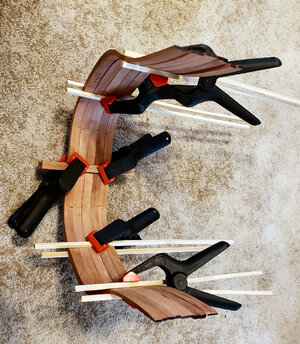
As far as I can tell, the first five frames are identical (probably the first six, but that one is being glued up at the moment). Holding them temporarily in place with some bamboo strips and clamps we have the first five:

20220107_125835.jpg
Some variation from frame to frame is due to thickness at that point (usually caused by both frame halves in a set not being exactly aligned during gluing, so once sanded, the overall thickness is less), not by design. The general shape is good, and close. I'll do some fine-tuning on thickness at some point to make them close to the same, although when I do that will be determined by my assembly method, which I am looking at differing from what everyone has done.

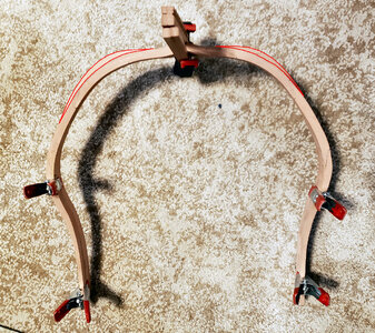
Looking at the group from this angle, I see I have one of the frames reversed, as the second from the right has an incorrect splice pattern. Obviously, none are in the proper position in the keelson, as they aren't properly spaced at this point, for dimension comparison, and I have the keelson in upside down just to help align the frames.
20220107_130049.jpg

One thing that's bothered me all along (well, since assembling the first frame), is that the ends of the frames, and frame halves, are not consistent. I'm sure that's my error, in sanding the joints too little or not keeping the joints tight (making the side higher), or sanding them too much (making the side lower). I'm not worried about it, because the entire top gets trimmed at the proper level.

What has bothered me from the beginning, is that knowing I have different heights to the frame, and that these frame tops insert into the jig for overall frame assembly, how the heck can deck and cannon opening dimensions be measured from a variable point?? I could trim them off even, but where? Here's a picture clearly showing that my frame tops are not level, and therefore IMHO not usable to measure from (nor use the frame jig as intended):
20220108_161254.jpg

Obviously, the jig cannot be used as intended without at least some modification of the frames. And which frame is the right height (if any). (I apologize if I'm the only one whose frames have turned out so different in height, but maybe someone else will have the problem later, right?) So all along, I've been intended instead to somehow work off the keel, to determine deck locations and cannon cutouts. I also think I should be able to make the frames more inline by doing it that way, but don't have it worked out yet, so won't say much about it.

I will mention that the plywood template the manufacturer gives us to determine the height of those items, when laid out and placed in line with the decks, the end opposite where the stand is glued appears to be at exactly the level of the bottom of the keel:

20220108_165124.jpg
In the above phot, the edge indicated by the red arrow should end up even with the bottom of the keel. So if I place the frames upright, and put this template on the same surface, it will properly indicate the deck and gun port levels. But I'll get into that more, once/if I have it all worked out.

As I said, I have all the frames made and sanded (to get rid of char at least, maybe not exact outline), except #6 which is being built up now. I want to show how much difference there is between frames 1 and 9, although all of this change occurs in frames 7-9. This is ignoring the small taper to the hull width, which the flexibility of the frames easily accommodates. Anyhow, the photo below shows that basically all the difference occurs in the middle two rib parts, B and C, with small amounts going into D:
20220108_161751.jpg
I've outlined the difference in areas in the above photo. Hopefully they are, or will be, close to each other in the result than the photo shows.

As always, please feel free to comment and suggest improvements, suggestions, alternate methods, etc. I'm on a journey here, very new to me in almost every way, and guidance of any kind will definitely help.

Knowing that I'm not THAT far away from wanting to put a finish of some sort on various pieces, no doubt some as I am assembling, I'm doing a little testing of those finishes, and also of methods of gluing finished parts together. You may be interested in this other topic concerning gluing on finishes and laser char as compared to bare wood. You will find that topic here: Test of Different Glues on Differing Surfaces.
 
Last edited:
Speaking of the Keel, does anyone have any thoughts concerning if this model should have a False Keel? I kind of thought most ships do, but this model does not. And of course it's easy enough to add.

Also, while talking about keels, would this ship have one or more keel scarfs to make up the entire keel? If so, that might be a good (mostly unseen) detail to add.
 
Dear Signet. I like your methodical approach to this build. I have a love/hate relationship with Unicorn. I built two of their sampans - the first one ended in the garbage bin (literally), and the second one turned out to be a museum piece (literally). The one thing I can tell you, is that their models do build into stunning final products - it is getting there that is the challenge. Take your time, work it out, ask questions and I am sure you will end up with something that you can be proud of.
 
G'day Signet, all that I can suggest for your frame's is to lay each one over the plan and add extra wood to take them to the correct height, you can add a piece of wood and sandwich it between two other pieces on each side of the frame, this at least will give you the correct height to fit them in the jig for sanding, and then after you can sand the excess off each side, hope this helps you,
Best regards John,
 
Dear Signet. I like your methodical approach to this build. I have a love/hate relationship with Unicorn. I built two of their sampans - the first one ended in the garbage bin (literally), and the second one turned out to be a museum piece (literally). The one thing I can tell you, is that their models do build into stunning final products - it is getting there that is the challenge. Take your time, work it out, ask questions and I am sure you will end up with something that you can be proud of.
Thanks, Heinrich. I'm actually enjoying this one so far, and am very impressed with the materials. But yeah, I'm taking my time and feel I'll have a lot of questions
 
G'day Signet, all that I can suggest for your frame's is to lay each one over the plan and add extra wood to take them to the correct height, you can add a piece of wood and sandwich it between two other pieces on each side of the frame, this at least will give you the correct height to fit them in the jig for sanding, and then after you can sand the excess off each side, hope this helps you,
Best regards John,
At this point, I'm thinking the frames are too long, if anything, and not too short so as to have to add material to. If I use the jig, I think I'll just have to cut off a portion of the tops to make them all the same (correct) height. If they're too high, or anything other than the correct height, then at least the hold will not be the wrong size, and everything will be shifted up or down when compared to the drawing.
 
In the end, I decided to assemble the frames pretty much as per the instructions, and as others have done. I did a couple other things first, though:

While the idea is to put frames in order, 1 through 9, I found 1 through 5 pretty much identical, so assembled them in order based on wider to narrower, thicker to thinner, with a progression from Fore (1) to Aft (9). Yes, I said their identical, but my work is not. There are slight variations in thickness, shape, etc. So by sorting them by their shape, rather than their number, I hope to minimize sanding to have a smooth progression from one end to the other.

Also, I mentioned previously that my frames are somewhat different in their height, as measured from the keelson to the top of the frames. I assume this is due to variations in sanding and assembly, not the kit itself. So using the deck height template and the cross section drawing, I determined that the top of the frame assembly jig would come about 3/8" above (below when upside down) the top of the rail. After marking this line on the plans, I took each frame, placed in in position based on the keelson, and marked the intersection that would be the top of the jig with each frame. I then sanded all the frames to that mark, so they will be consistent.

I realized just now when writing this, and looking at the drawing, that I cut off all the frames too short by the thickness of the jig bottom, or 4 mm. Luckily, that won't cause me a problem, if I also shorten deck height template by the same amount. Regardless, I will confirm the deck heights, and therefore the gun port template locations, with the drawing before I mark and mount everything.

This is how the frame assembly looks after assembly:
20220110_144336.jpg
I had wanted to cut the gun port openings in the frames before assembly, to keep them more precise, but abandoned that in the end. I'll use a hand coping saw, which I should be able to get between the frames, to make the horizontal cuts. If that doesn't fit, a jeweler's saw will work.

After drying a while, I placed clamps from end to end where the top row of reinforcing strips go, and super-glued to the inside against the frames, connecting them together. There were slight gaps which the glue might not have spanned, so that's why I clamped. I'll do the same to the other two rows of reinforcing strips, before breaking it loose from the jig. While I cut short the lower 2 rows (to the keel), my intention is to keep the top row in place as long as I can, at least some of them, to help maintain the shape of the upper portion.

I'll also be adding some extra bracing from the cut out strips to place near the thick hull members, which should be not be too near a cutaway area. The same nearer the top rail at some point, but that may wait a while.

Question: I notice that the Deck 3 cross beam locating template has most of the Orlop deck completely open, and the plan view of Deck 3 (Orlop deck) shows the same thing. I realize that the water pump enclosure and ammunition locker occupy this space, but I'm very surprised that there are only 5 cross beams versus the 8 on the decks above, and that there is this large open space. While this isn't a gun deck, I'd still think there would be cross members, and some decking, in that area. The kit without the inside details shows it as just open:

1641848385938.png
The area outlined in red is what I'm talking about. On the version with the inside details, which I am building, there are additional cross beams, but only stripwood, not laser-cut beams. and in areas of the carpenter's walk, no support at all for the approximate 10' 6" long planked area.

I guess it's nothing. Just seems like 1 major cross beam is left out on either build, and the area is not well reinforced, and if you don't get the interior option, they just give you a hole with no decking or cabins at all.
 
I'm having a problem finding the right part for a portion of the mast step area. Stan167 has the clearest picture I've found of this, so I will post his pic (hopefully he doesn't mind):
1641873881975.png
(Wonderful nails/bolts/treenails BTW; it's a shame it all gets covered up by the pump well.)

I've identified all the parts except the slanted pieces that form a wedge at the bottom of the mast, identified with red arrows above. On the plan cross section these are identified as parts 1512:
1641874973568.png

Below is a picture of parts 1512, showing where they were taken from, confirming the right part number:
1641874084827.png

This can't be right. For reference, a longitudinal section drawing shows this area as:

1641874218265.png

I've found the pieces 1511, which are just rectangles which are to be tapered and installed at an angle (Although I don't see anything specified to form the triangular shaped piece to either side which keeps the pieces at the correct angle).

Anyhow, I can't find the correct pieces for the parts pointed to with red arrows above. The shape should be a really fat T, basically a rectangle, with the upper half of the rectangle extended to fit into the top half of members on either side. Based on the slot size on either side, it should be of 4mm stock.

Anyone have any ideas where those are? Or do I have to make them myself (not that it would be difficult). I'll be really embarrassed if someone points out where the part is, but it will be worth it to have the part.
 
Back
Top