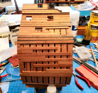
Thanks very much, Uwe. I tried to do the outer planking in the 13542 sequence, to make it look more like they were in the process of planking it, rather than having removed some to view the structure. I'm retired and pretty inactive, so I spend most of my time either working on the model, researching the model, or admiring other work such as yours. But as you know, the inside structure and details is what takes the time, while the outer planking goes fairly quickly. I just like having as much "cutting and sanding" done as possible before working more on the inside.Very good progress - you are a very fast modeler
and it is looking very very good
btw: I like your way of partly planking the outer hull, so we can see the structire of the frames behind very good
It is getting a very good model - Bravo!
You are using an out of date browser. It may not display this or other websites correctly.
You should upgrade or use an alternative browser.
You should upgrade or use an alternative browser.
Signet's Bonhomme Richard Cross Section [COMPLETED BUILD]
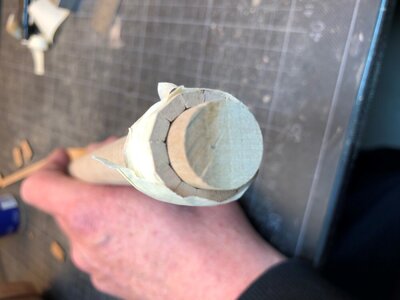
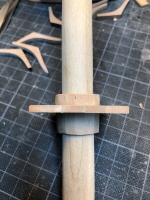
I haven't posted for a bit, but have continued to plan and to build. I previously made the four bilge pump assemblies. Probably should have left the pistons in the down position, as the plans and everyone shows, as they fall to that position by gravity, but I thought part of the upper rod exposed looked better. I think I was wrong:
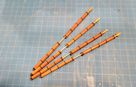
The upper and lower tubes are 8-sided, as they should be, but not really "octagonal". But then the won't be that visible. I used brass rods to connect the upper and lowers, to simulate the bronze tubing. I also put small brass washers at the ends, which adds a touch of detail, albeit inaccurate detail. But they shine and look pretty good. The tape used to simulate straps isn't staying put very well. I put one coat of Danish Oil on, then a light coat of matte clear spray for the tape to stick, then another coat of matte to hold the tape, but it almost seems to have lifted it, rather than hold it.
I found that I should be able to slide the lower gun deck (Deck 2 in the model) into place, and wanted to plan for cutting the orlop deck's "cabins" (actually vegetable storage rooms) up into the deck above, so went ahead and started the deck. Not sure what decking I will add on this deck; may leave one side showing all the structure, and fully deck the other:
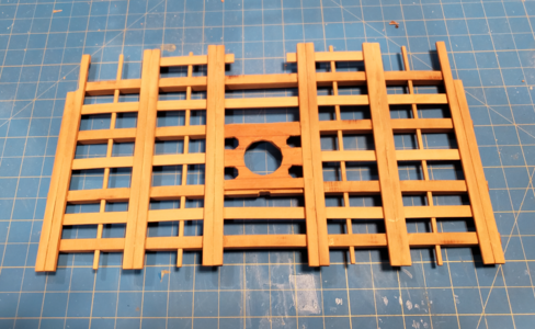
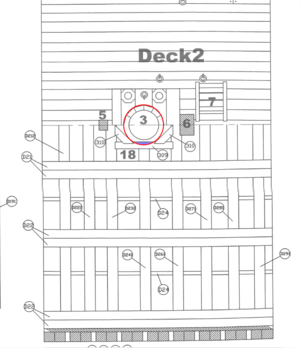
Uwe's excellent build log on this model details the problem with the main mast partners interfering substantially with the the "shims" surrounding the main mast to secure it. The drawing below shows how it interferes:
He made the entire area around it from scratch, but I ended up using it and simply used 2x6mm wood to make revised partners that seem logical to me, secure the area and aren't that visible anyhow:
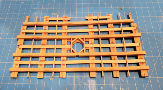
Most of the members are glued with white glue, but the 1x6mm strips I simply slid in place and super-glued them. Thus the darker stains at the glue points. But once coated with Danish Oil, they don't show up, except they're always a bit glossy, which I can fix if I like with matte spray.
I finally mounted the upper part of the pump well and shot locker in place, after making sure that the floor above fits in place. Also added 3 sizes of cannon balls, the one at left "filled" with 12# shot, the center partly filled with 18# shot and the rightmost one partly filled with 9# shot.
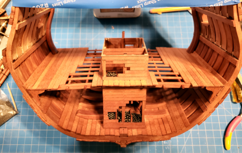
All of the shot is a little oversize, but there's a reason: The model includes only two sizes of barrels, two to simulate the 18# guns, and four to simulate both the 12# and 8# guns. The kit includes cannon balls which are 2.96mm in diameter. They just fit in the larger barrels, while the smaller barrels are about 2.75mm inside diameter.
Correction: See next post:
The 2.96mm cannon balls in 1/48 scale work out to about 142mm diameter, or 5.59" in diameter. which works out to about a 37# cannon ball. To be the correct scale, the 18# ball (4.403" in diameter) should be 2.33mm in size, the 12# ball (3.896" in diameter) should be 2.06mm in size, and the 8# ball (3.36" in diameter) should be 1.78mm in size. I was going to go that way, but realized that even the largest cannon ball would look small compared to the kit's barrel bores. So I moved everything up a size or so: I ended up using #9 lead shot (2.0mm in diameter) for the 9-pounders, #7 1/2 lead shot (2.3mm in diameter) for the 12-pounders and #5 lead shot (2.8mm in diameter) for the 18-pounders. Still slightly large (like many ship model hardware items), but closer to correct, and don't look too out-of-place with the existing barrels. And the progression in size "seems" about right to me.
Now to work on the cabins on the orlop deck, hoping I can install them either before, or during, installation of the lower gun deck.

The upper and lower tubes are 8-sided, as they should be, but not really "octagonal". But then the won't be that visible. I used brass rods to connect the upper and lowers, to simulate the bronze tubing. I also put small brass washers at the ends, which adds a touch of detail, albeit inaccurate detail. But they shine and look pretty good. The tape used to simulate straps isn't staying put very well. I put one coat of Danish Oil on, then a light coat of matte clear spray for the tape to stick, then another coat of matte to hold the tape, but it almost seems to have lifted it, rather than hold it.
I found that I should be able to slide the lower gun deck (Deck 2 in the model) into place, and wanted to plan for cutting the orlop deck's "cabins" (actually vegetable storage rooms) up into the deck above, so went ahead and started the deck. Not sure what decking I will add on this deck; may leave one side showing all the structure, and fully deck the other:

Uwe's excellent build log on this model details the problem with the main mast partners interfering substantially with the the "shims" surrounding the main mast to secure it. The drawing below shows how it interferes:

He made the entire area around it from scratch, but I ended up using it and simply used 2x6mm wood to make revised partners that seem logical to me, secure the area and aren't that visible anyhow:

Most of the members are glued with white glue, but the 1x6mm strips I simply slid in place and super-glued them. Thus the darker stains at the glue points. But once coated with Danish Oil, they don't show up, except they're always a bit glossy, which I can fix if I like with matte spray.
I finally mounted the upper part of the pump well and shot locker in place, after making sure that the floor above fits in place. Also added 3 sizes of cannon balls, the one at left "filled" with 12# shot, the center partly filled with 18# shot and the rightmost one partly filled with 9# shot.

All of the shot is a little oversize, but there's a reason: The model includes only two sizes of barrels, two to simulate the 18# guns, and four to simulate both the 12# and 8# guns. The kit includes cannon balls which are 2.96mm in diameter. They just fit in the larger barrels, while the smaller barrels are about 2.75mm inside diameter.
Correction: See next post:
The 2.96mm cannon balls in 1/48 scale work out to about 142mm diameter, or 5.59" in diameter. which works out to about a 37# cannon ball. To be the correct scale, the 18# ball (4.403" in diameter) should be 2.33mm in size, the 12# ball (3.896" in diameter) should be 2.06mm in size, and the 8# ball (3.36" in diameter) should be 1.78mm in size. I was going to go that way, but realized that even the largest cannon ball would look small compared to the kit's barrel bores. So I moved everything up a size or so: I ended up using #9 lead shot (2.0mm in diameter) for the 9-pounders, #7 1/2 lead shot (2.3mm in diameter) for the 12-pounders and #5 lead shot (2.8mm in diameter) for the 18-pounders. Still slightly large (like many ship model hardware items), but closer to correct, and don't look too out-of-place with the existing barrels. And the progression in size "seems" about right to me.
Now to work on the cabins on the orlop deck, hoping I can install them either before, or during, installation of the lower gun deck.
Last edited:
While I'm sure I got the cannon bore dimensions from a reputable source (going by my notes from a month or two ago), I see that they differ from those published by Bourdriot's concerning the Bonhomme Richard and The Seventy Four Gun Ship. He lists the bores for the 18#, 12# and 8# (not 9# as mentioned above) as 138mm, 121mm and 106mm respectively. The scaled down sizes for each would then be 2.87, 2.52 and 2.21mm. Turns out my sizes of 2.8, 2.3 and 2.1mm are just slightly smaller, rather than slightly larger, but close enough for (French) Government Work. Sorry for the error.
Length of the gun barrels included in the kit are reasonably accurate: the larger barrels, representing the 18-pounders, scale 9.5' long compared to Bourdriot's dimension of 9' for the "Old" style mounted on the ship. The 12-pounders were of both new and old style, measuring 7.5' and 8.5' long respectively, while the model barrels hit an average of 8' long. The 8-pounders were listed by Bourdriot as 6.83' long for the BH while The 74 lists 9-pounders as 7.29' long; the model uses the same barrel for the 8# and 12# guns - 8' long. So mostly the 8-pounders are a bit oversize. A difference not worth seeking replacements for, IMHO.
Length of the gun barrels included in the kit are reasonably accurate: the larger barrels, representing the 18-pounders, scale 9.5' long compared to Bourdriot's dimension of 9' for the "Old" style mounted on the ship. The 12-pounders were of both new and old style, measuring 7.5' and 8.5' long respectively, while the model barrels hit an average of 8' long. The 8-pounders were listed by Bourdriot as 6.83' long for the BH while The 74 lists 9-pounders as 7.29' long; the model uses the same barrel for the 8# and 12# guns - 8' long. So mostly the 8-pounders are a bit oversize. A difference not worth seeking replacements for, IMHO.
- Joined
- Oct 17, 2020
- Messages
- 1,336
- Points
- 393

Yeah, another one. There are already so many builds, of such high quality, that I'm sure you're thinking we don't need another one. But I'm hoping that my build might provide some interesting discussion, and the build will definitely be from a professional non-perfectionist viewpoint. Besides, Uwe asked me to do it.
I won't go through opening the kit, as there are so many other threads with better coverage. I'll try to cover some things I haven't seen, or perhaps that I've done differently. Please excuse my clumsy start and initial photos; I'm taking pictures with my phone, and am not sure how they will turn out or how this will read, so today's posts are practice, and hopefully they will later improve.
The first thing I did after receiving the kit (full pear version, with interior, barrels, and carved belfrey and railing) for Christmas was to go to Staples. There is just one large sheet of plans, 34" x 48", and of course folded:
View attachment 279359
This makes it a bit hard to work with, especially without ruining the original plans, so I had Staples make 2 full-size copies ($6 each), and also a file of the image in PDF format. I cut up one of the large copies, including small details that related to each other in each separate "sheet", but most are copies of the larger cross sections and views I will be relating to. I am able to easily work with the smaller sheets, and protect them with glass or wax paper during work, so as not to have to keep making copies.
A topic of conversation here about this kit is the lack of English instructions. It appears that Unicorn has heard our pleas, as there is a fair amount of English translations currently included with the kit. If you zoom in on these plans, you will see that area titles and some notes have been translated from Chinese to English. I used Google Translate to view translations to confirm their validity (included translations in general are better than Googles) and make any notes or changes. The 30+ page instruction manual is all photos and pictures, but they have included 6-pages which list Chinese and English for each step:
View attachment 279361
While not elaborate, they are definitely helpful. If anyone building this kit does not have the translations, please let me know and I'll post a copy that you can print.
The optional Interior Kit has instructions on 8 A4 sheets (8.25" x 11.5") and includes both Chinese and English:
View attachment 279387
I decided to start the kit by doing a complete frame, as I knew there would be a lot more to come, and I wanted to practice, get ideas, and maybe get more ideas from you. I chose Frame 2 to start, as 1) It wasn't as visible as 1 or 9, which show at the outside, nor did it contain any cuts for gun ports (more on that later). While the quality of the stripwood is fantastic, as is the quality of the wood with the laser-cut parts, I'm not as happy with the laser-cut parts. First, they're hard to "punch" out, requiring cuts with a blade in the uncut areas. Someone mentioned using a "sturdy" blade, so I used a retractable utility knife. It didn't do badly, but I still had to cut both sides, and I found the long blade would sometimes cut into areas I didn't want. I'm going to try a shorter, thinner scalpel blade to see if it does better. One of my problems is that cataract surgery has left my "good" eye no longer able to see at close distances, so I have to switch to strong reading glasses (3.0, 4.5 and 6.0) to see close stuff. I /think/ I'm cutting right without them, then see my errors with them.
The second disappointment is that the laser cuts are not perpendicular to the surface. Although they appear much larger, I've measured them at 2-6 degrees, probably averaging midway. This results in a bad fit without sanding, a lot of sanding for a good fit, an pieces end up a bit narrower than they should be when done on both sides. Neptune, in his excellent build log, mentioned to keep the same face of the wood upright when building the frames; I suspect the angle, which he also mentions, is the reason for this. I tried switching around trying for a better fir without sanding as much, but that didn't help. These pics give you an idea of the angle (ruler is shoved in tight to a cut joint):
View attachment 279370
The notch where the keel fits into the lower frame (floor?) notches is tight, so it ends up at an angle too:
View attachment 279371
I have to file the openings somewhat larger so the frames will fit the keel when at a right angle.
As much for practice photography and testing, here are a pile of frames before sanding the joining areas:
View attachment 279372
And afterwards:
View attachment 279373
I sanded them at right angles to the outline surface, just taking off the char in this area now. It's easy to sand too much off and not notice it. This applies to the end and "notched" areas, especially. I found that when I had a mating pair about right, I could hold them an "rock" them back and forth, to see if one end was a bit too long, and if so, sand it down to fit better.
For my first frame assembly I used clothespins to secure the joints. I tried the plastic clamps, but the frame thickness was too small. Also, I tried Elmer's Glue-All, but it didn't dry fast enough to suit me, so switched to Titebond Quick & Thick, which I'm happy with so far.
View attachment 279374
This clamping method didn't work out that well for me, though. When doing the second half, I found that the clamping force of the clothespins on the sloped scarf cause the pieces to slide and separate, and I didn't see that until picking the piece of some time later. I used water and slowly separated the pieces on that half, cleaned it up and redid it. This time I placed clothespins like this:
View attachment 279376
This clamped each clamping edge on part of each piece, keeping it snug, but not causing the slide. I've ordered 20 2" metal clamps which I hope to use in the future with better results.
I wasn't sure whether to build up a second half-frame (the two are fastened together) and glue it over the first, or build up the second on top of the first. In the end I chose the second method, feeling I'd keep alignment better, and I think it did:
View attachment 279377
I used two of the keep pieces clamped in place to keep the two floors in alignment. Then added, and clamped, added and clamped.
View attachment 279378
After drying overnight, I sanded the inner and outer char off. Alignment wasn't as good as I'd hoped, and the section is slightly thinner than it should be because of this. I hope my other frames, using a different clamping system, will be better. I've also glued the first four parts of the keel together with the bevels for planking. I found this easier to assemble two pieces at a time, true up, then continue.
View attachment 279381
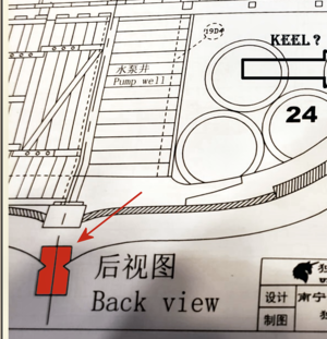
Speaking of the keel, I've come to my first question (I'm hoping I will get more from you during this thread than I will show you): Shouldn't there be a FALSE KEEL on the model? I'm not that familiar with the construction of French ships, but thought this was pretty much standard: a replaceable timber to protect the keel and its joints. I can easily add a piece to the bottom, of course, but didn't want to if it shouldn't be there.
My second question refers to the jig that is included for frame alignment:
View attachment 279386
I've followed its use in the instructions, but wonder: Why is the large, mostly-rectangular section of the bottom plate left loose to move? I thought at first it was to be removed, but it isn't. The little "bridges", shown in 4 locations with the red arrows, are what attach this section to the rest of the bottom plate. Allowing it to move slightly vertically. The frames don't fit that tight, and I have NO idea why this was done this way. Does anyone know? Also, the 8 rectangular cutouts on the section, one pointed to by the blue arrow, seem to have a specific outline and maybe a purpose? Again, I have no idea.
, that's my first installment. In the future, I will try to include more/better content, less pictures and more "unique" stuff. We will see. PLEASE don't hesitate to point out things I've done wrong, suggest alternate ways of doing things, etc. In short, help make me a better modeler, and this a better model.
Good evening Signet, I'm sorry but, what's the keel? Thank youIn the end, I decided to assemble the frames pretty much as per the instructions, and as others have done. I did a couple other things first, though:
While the idea is to put frames in order, 1 through 9, I found 1 through 5 pretty much identical, so assembled them in order based on wider to narrower, thicker to thinner, with a progression from Fore (1) to Aft (9). Yes, I said their identical, but my work is not. There are slight variations in thickness, shape, etc. So by sorting them by their shape, rather than their number, I hope to minimize sanding to have a smooth progression from one end to the other.
Also, I mentioned previously that my frames are somewhat different in their height, as measured from the keelson to the top of the frames. I assume this is due to variations in sanding and assembly, not the kit itself. So using the deck height template and the cross section drawing, I determined that the top of the frame assembly jig would come about 3/8" above (below when upside down) the top of the rail. After marking this line on the plans, I took each frame, placed in in position based on the keelson, and marked the intersection that would be the top of the jig with each frame. I then sanded all the frames to that mark, so they will be consistent.
I realized just now when writing this, and looking at the drawing, that I cut off all the frames too short by the thickness of the jig bottom, or 4 mm. Luckily, that won't cause me a problem, if I also shorten deck height template by the same amount. Regardless, I will confirm the deck heights, and therefore the gun port template locations, with the drawing before I mark and mount everything.
This is how the frame assembly looks after assembly:
View attachment 281837
I had wanted to cut the gun port openings in the frames before assembly, to keep them more precise, but abandoned that in the end. I'll use a hand coping saw, which I should be able to get between the frames, to make the horizontal cuts. If that doesn't fit, a jeweler's saw will work.
After drying a while, I placed clamps from end to end where the top row of reinforcing strips go, and super-glued to the inside against the frames, connecting them together. There were slight gaps which the glue might not have spanned, so that's why I clamped. I'll do the same to the other two rows of reinforcing strips, before breaking it loose from the jig. While I cut short the lower 2 rows (to the keel), my intention is to keep the top row in place as long as I can, at least some of them, to help maintain the shape of the upper portion.
I'll also be adding some extra bracing from the cut out strips to place near the thick hull members, which should be not be too near a cutaway area. The same nearer the top rail at some point, but that may wait a while.
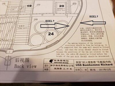
Question: I notice that the Deck 3 cross beam locating template has most of the Orlop deck completely open, and the plan view of Deck 3 (Orlop deck) shows the same thing. I realize that the water pump enclosure and ammunition locker occupy this space, but I'm very surprised that there are only 5 cross beams versus the 8 on the decks above, and that there is this large open space. While this isn't a gun deck, I'd still think there would be cross members, and some decking, in that area. The kit without the inside details shows it as just open:
View attachment 281839
The area outlined in red is what I'm talking about. On the version with the inside details, which I am building, there are additional cross beams, but only stripwood, not laser-cut beams. and in areas of the carpenter's walk, no support at all for the approximate 10' 6" long planked area.
I guess it's nothing. Just seems like 1 major cross beam is left out on either build, and the area is not well reinforced, and if you don't get the interior option, they just give you a hole with no decking or cabins at all.
- Joined
- Oct 17, 2020
- Messages
- 1,336
- Points
- 393

sorry I wanted to mention the fifths
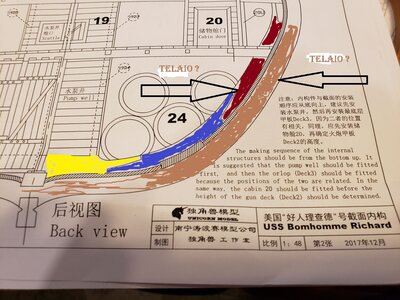
Sorry, I don't know what you're referring to. Can you elaborate?sorry I wanted to mention the fifths
The frame is colored brown.
yellow, blue and red are the elements of a rider
between the frame and the rider is the inner planking
- Joined
- Oct 17, 2020
- Messages
- 1,336
- Points
- 393

Hello Uwek, Thank you for answering me, the translation is not clear to me, I'll try with a nautical vocabularyThe frame is colored brown.
yellow, blue and red are the elements of a rider
between the frame and the rider is the inner planking
Continuing on, kind of haphazardly,
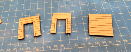
Working on the carpenter's walk walls first, I try to use the sheets of planking without separating. It gives an very tightly spaced and charred line that I like the appearance of:
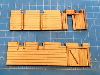
Note the bracing around the beam cutout openings to help attach the planking. Super glue is really glossy here and shows up less in real life, blends in once finish is applied, and can be sprayed matte to eliminate any gloss.
Laying out the door openings on sheet planking, then putting trim around doors:
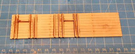
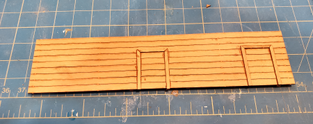
My kit did not include enough trim for inside of doors, so I used the 2x2mm strips to reinforce the areas, and they can't be seen from the outside.
After cutting the openings: And after separating them, VERY roughly. They get sanded flush later.
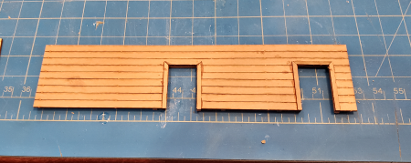
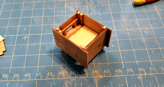
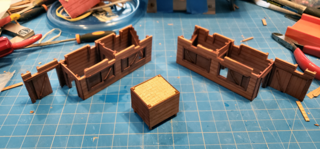
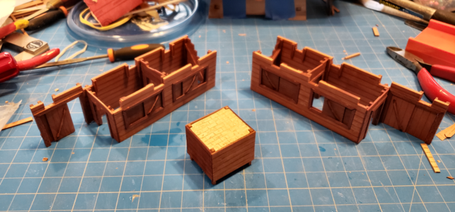
The almost-complete walls of the storage rooms and carpenter's walk partition, ready for fitting, trimming and assembly:
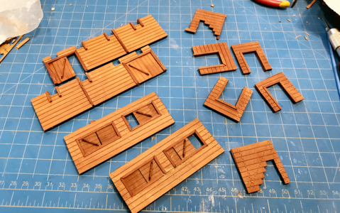
This and some other photos show additional bracing I added around openings for cross beams. IMHO, the structures would HAVE to have some added bracing, to attach the planks to, just as I had to have. They'd probably go the full height of the wall, though, on one side or the other of the carpenter's walk.
I worked on the Bread Oven next, making the walls in similar manner, again using multiple planks in a sheet. I had to add additional bracing this way, as only 2 walls have the required corner supports, so the other two have supports inboard of this, and added supports around the opening to the oven. Yes, I know it's all sloppy work, but will be hidden. And I was tired. And it was late. And my cat told me to go to bed an hour ago:
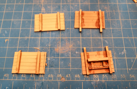
After basic assembly of the oven. The template piece is about to become the floor of the oven, as I mistakenly thought it might be possible to see inside:
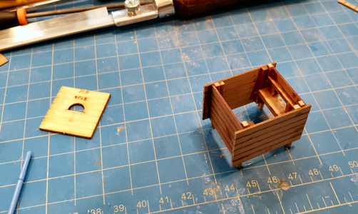
Ended up using another piece of template, due to the hole, but the same idea:
I didn't feel I could get a very realistic fire brick effect by using the wood pieces. Fire brick has pretty much always been a light beige color, although in recent times they colorants to make them different colors. Just look at the inside of a ceramic kiln or inside of an old fireplace.
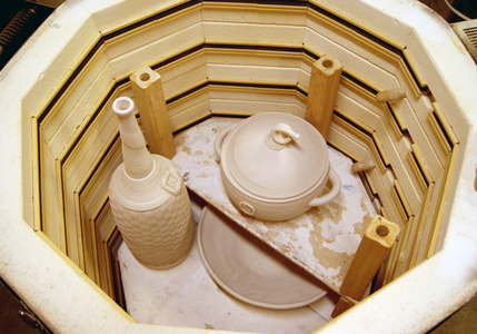
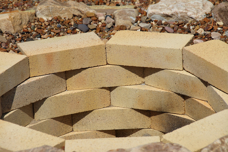
I chose to simulate the brick area using oven-hardened modeling clay, Fimo brand, in a nice beige color called Sahara (probably should have been South Carolina, based on the summers here) that matches the fire brick in my wife's kiln:

I wanted to mould the clay in place in the top of the oven, and then heat the whole thing, to make sure it would fit. As a test, I glued a couple pieces of pear scrap together and made a flat blob of clay, cut to a specific with a couple lines, and baked them both at 230 degrees for 30 minutes. Afterwards, there was no distortion of the clay, the width dimension didn't change and the wood and glue strength was not affected:
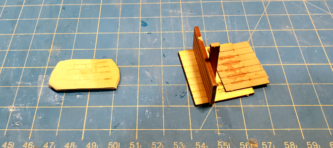
Sorry, the colors of the clay look yellow here (as does the template material). They're both a dead ringer for the clay product picture above, and match well to fire brick to my mind.
I moulded a blob of clay about 1/10" thick somewhat larger than my oven, then turned the over upside down and made an impression with it:
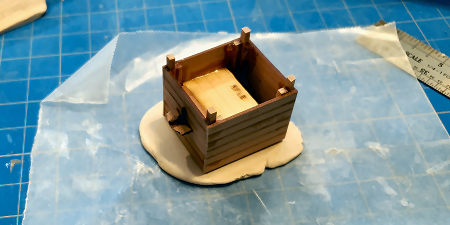
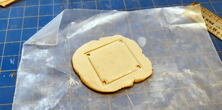
Note I trimmed the extra braces short before doing this so they would not be affected by the clay.
I trimmed the clay easily with an Exacto knife, then placed it into the oven top. I scored some brick outline into the top to give the impression of bricks, although at this scale they would probably not be visible, as they fit very tight. Also found my oven wasn't quite the right dimensions, and doing the bricks by eye, it looks a bit sloppy, but it will have a deck right over it, and I didn't feel like doing another one.
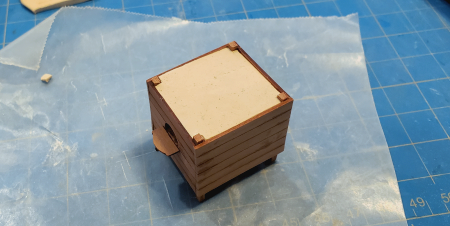
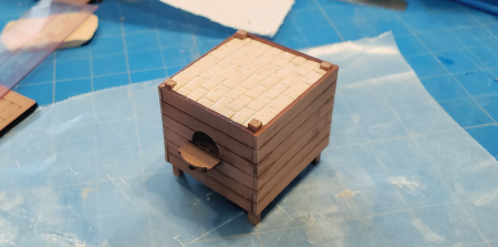
The completed storage rooms and oven, minus some final trim and possibly some matte spray to eliminate any super glue gloss:
This picture shows the fire clay too yellow. The other pictures prior to this are more representative. I used a bit of brown ink wash to "smudge" up the brick a bit (it doesn't really change color with heat, but certainly will get dirty).
A view of the structures in place on the orlop deck, with the lower gun deck structure above, all just placed there for testing:
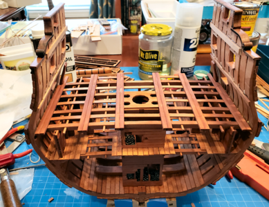
Still not sure if I will glue the structures in place, then squeeze the gun deck over and down into place, or slide them all in together, and tack the structures in place afterwards. But that's a decision for another day.
Played around with adding some stain over the designated "black" areas, but didn't turn out well, as it is blotchy, not very dark and not even:
I've experimented a bit with some Minwax Polyshade in Bombay Mahogany, which is a semi-transparent varnish with stain built-in. I think I will brush over those areas I want darker, and think/hope it will give a decent effect. I'll probably wait until most of the interior is done, though, to eliminate added handling of the finish. Also note the two rectangular openings for 3mm square brass tubing "drains" to be located on the lower gun deck, as documented by Uwek here.
.
I've been avoiding working on the wedges around the main mast partners on the lower gun deck. Guess I better do some work on that before long.
Working on the carpenter's walk walls first, I try to use the sheets of planking without separating. It gives an very tightly spaced and charred line that I like the appearance of:

Note the bracing around the beam cutout openings to help attach the planking. Super glue is really glossy here and shows up less in real life, blends in once finish is applied, and can be sprayed matte to eliminate any gloss.
Laying out the door openings on sheet planking, then putting trim around doors:


My kit did not include enough trim for inside of doors, so I used the 2x2mm strips to reinforce the areas, and they can't be seen from the outside.
After cutting the openings: And after separating them, VERY roughly. They get sanded flush later.


The almost-complete walls of the storage rooms and carpenter's walk partition, ready for fitting, trimming and assembly:

This and some other photos show additional bracing I added around openings for cross beams. IMHO, the structures would HAVE to have some added bracing, to attach the planks to, just as I had to have. They'd probably go the full height of the wall, though, on one side or the other of the carpenter's walk.
I worked on the Bread Oven next, making the walls in similar manner, again using multiple planks in a sheet. I had to add additional bracing this way, as only 2 walls have the required corner supports, so the other two have supports inboard of this, and added supports around the opening to the oven. Yes, I know it's all sloppy work, but will be hidden. And I was tired. And it was late. And my cat told me to go to bed an hour ago:

After basic assembly of the oven. The template piece is about to become the floor of the oven, as I mistakenly thought it might be possible to see inside:

Ended up using another piece of template, due to the hole, but the same idea:

I didn't feel I could get a very realistic fire brick effect by using the wood pieces. Fire brick has pretty much always been a light beige color, although in recent times they colorants to make them different colors. Just look at the inside of a ceramic kiln or inside of an old fireplace.


I chose to simulate the brick area using oven-hardened modeling clay, Fimo brand, in a nice beige color called Sahara (probably should have been South Carolina, based on the summers here) that matches the fire brick in my wife's kiln:

I wanted to mould the clay in place in the top of the oven, and then heat the whole thing, to make sure it would fit. As a test, I glued a couple pieces of pear scrap together and made a flat blob of clay, cut to a specific with a couple lines, and baked them both at 230 degrees for 30 minutes. Afterwards, there was no distortion of the clay, the width dimension didn't change and the wood and glue strength was not affected:

Sorry, the colors of the clay look yellow here (as does the template material). They're both a dead ringer for the clay product picture above, and match well to fire brick to my mind.
I moulded a blob of clay about 1/10" thick somewhat larger than my oven, then turned the over upside down and made an impression with it:


Note I trimmed the extra braces short before doing this so they would not be affected by the clay.
I trimmed the clay easily with an Exacto knife, then placed it into the oven top. I scored some brick outline into the top to give the impression of bricks, although at this scale they would probably not be visible, as they fit very tight. Also found my oven wasn't quite the right dimensions, and doing the bricks by eye, it looks a bit sloppy, but it will have a deck right over it, and I didn't feel like doing another one.


The completed storage rooms and oven, minus some final trim and possibly some matte spray to eliminate any super glue gloss:

This picture shows the fire clay too yellow. The other pictures prior to this are more representative. I used a bit of brown ink wash to "smudge" up the brick a bit (it doesn't really change color with heat, but certainly will get dirty).
A view of the structures in place on the orlop deck, with the lower gun deck structure above, all just placed there for testing:

Still not sure if I will glue the structures in place, then squeeze the gun deck over and down into place, or slide them all in together, and tack the structures in place afterwards. But that's a decision for another day.
Played around with adding some stain over the designated "black" areas, but didn't turn out well, as it is blotchy, not very dark and not even:

I've experimented a bit with some Minwax Polyshade in Bombay Mahogany, which is a semi-transparent varnish with stain built-in. I think I will brush over those areas I want darker, and think/hope it will give a decent effect. I'll probably wait until most of the interior is done, though, to eliminate added handling of the finish. Also note the two rectangular openings for 3mm square brass tubing "drains" to be located on the lower gun deck, as documented by Uwek here.
.
I've been avoiding working on the wedges around the main mast partners on the lower gun deck. Guess I better do some work on that before long.

Last edited:
I have a question concerning the Bread Oven on ships like this. The following drawing shows that it is held in place on the deck with four iron rings attached to four eyebolts toward the bottom of the four legs:
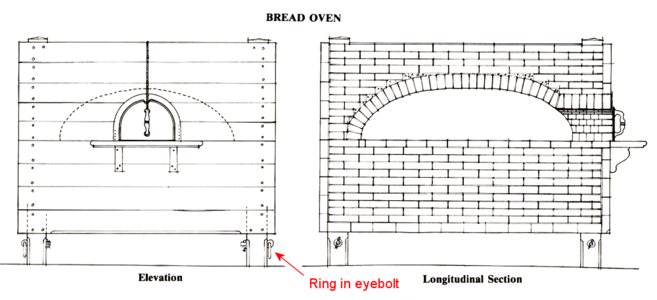
My question is: how would the ring be attached to the deck. At first I though an iron hook or similar, and that's possible, but it would have to be hooked to the ring, then probably drilled through the deck possibly clenched under the deck to tighten it down. It could be roped to something, but for an item as permanent as the oven, the bolt with hook makes more sense to me. Does it to you? Do you know what methods may have been used?

My question is: how would the ring be attached to the deck. At first I though an iron hook or similar, and that's possible, but it would have to be hooked to the ring, then probably drilled through the deck possibly clenched under the deck to tighten it down. It could be roped to something, but for an item as permanent as the oven, the bolt with hook makes more sense to me. Does it to you? Do you know what methods may have been used?
I decided to attack the mast connection and support on the lower gun deck with its wedges next. The installation is shown in the instructions like this:
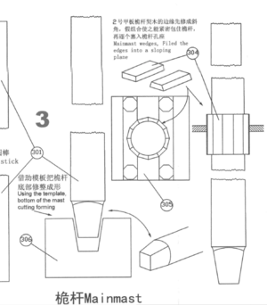
The wedges here are shown as not tapered, but in fact they were tapered so as to both be able to be hammered tight, and to adjust the perpendicularity of the mast. I decided to make mine tapered vertically, like the actual ones, although tapered more than originally, to make them easier to fit.
I took measurements of the mast (15.6mm in diameter) and the inside of the 12-sided opening for the wedges across flats (20.75mm). and made a layout:
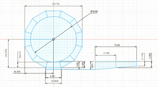
The thickness of the wedges end up just over 2mm, so I decided to use 3mm stock, full thickness at the top and tapered toward the bottom. I used 3x6mm pear from the kit, although I couldn't spare it because I didn't have enough for the decks, but I'll make do. The full 6mm width is close enough to the above drawing's 5.904mm, so can be used as-is.
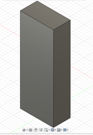
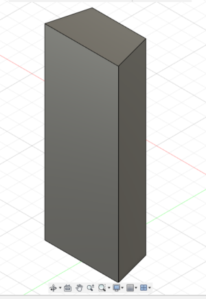
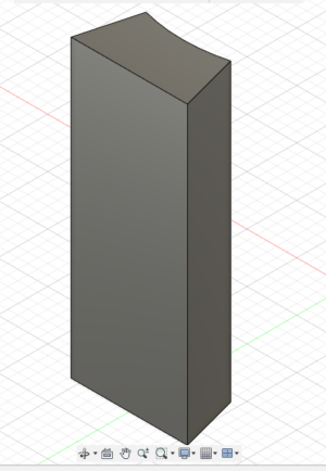
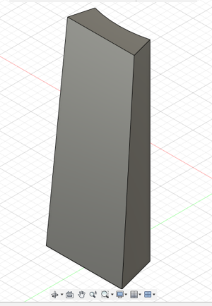
This photo shows the end of the strip after having the two 15 degree bevels applied and the radius. The radius isn't very visible in this photo, but it's there:
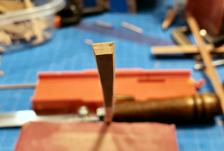
Checking the end thickness prior to cutting off the wedge:
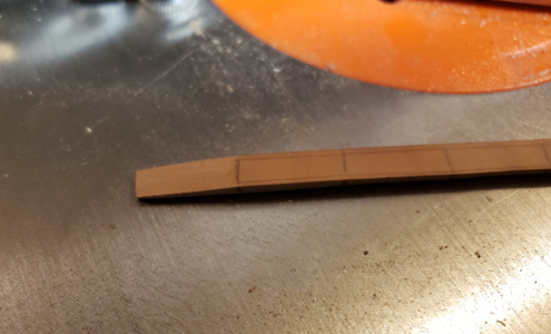
The completed wedge, prior to being cut off the strip:
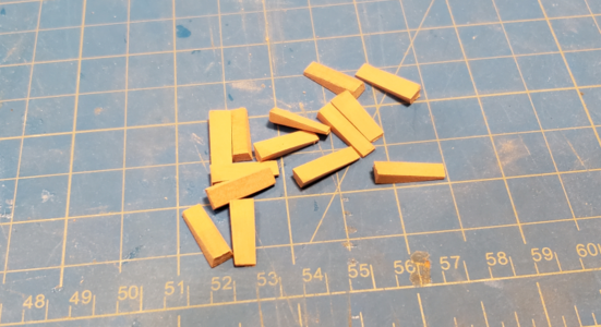
Completed wedges:
NOTE: Before proceeding with the mast and wedges in the model, MARK THE MAST near its bottom to indicate the side facing the #1 rib on the model. The installed mast will probably NOT fit well if rotated to any other position.
With the lower gun deck, to which the mast attaches, temporarily held in place, I add two wedges opposite each other:
Do NOT glue wedges in place during this adjustment operation.
I checked the dimension from the mast to the inner side of the hull on each side to be sure it's vertical side-to-side. Wedges are adjusted (pull one out slightly, push the other in) to get it centered:
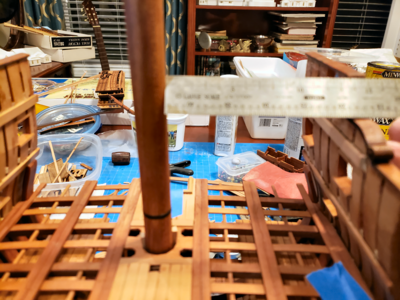
Sorry. Didn't notice I'd focused on the wrong area.
Continue by installing wedges toward the front and back:
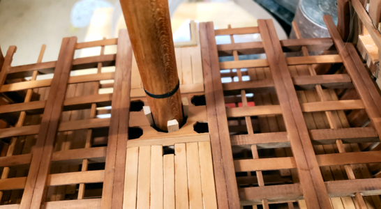
As it was hard to determine vertical on the model this way, I eyed it as being parallel to the hull ribs.
Continue around placing wedges, without gluing, until it's how you want it:
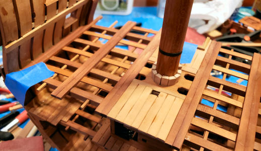
After you're happy with the placement, take one wedge out at a time, super glue the curved side toward the mast, and replace it. do this for all the wedges. After the glue has dried, you can remove the mast, with wedges attached. If one or more fall off, you probably missed gluing them; replace the mast and reglue any loose wedge:
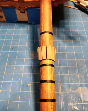
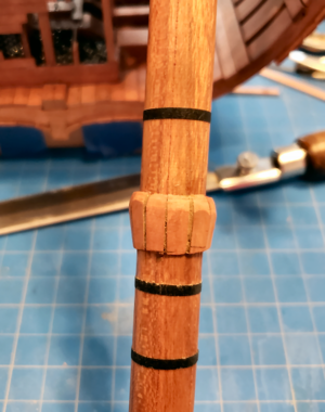
The right photo above shows some trimming and rounding done to the top of the wedges (above the deck). Don't touch the flat areas that contact the deck.
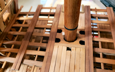
In place, the mast fits quite snuggly, yet is easily removed, and can be permanently glued in place later when desired. BTW, I placed a brass pin centered in the bottom of the mast to more precisely locate the bottom of the mast.
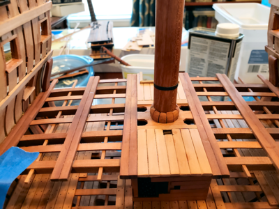
I think it looks pretty good and definitely holds the mast securely.
Note that there are gaps, etc. in my mast support; I used the wrong dimensions when making the strip width, and then when doing a preliminary fit, the wedges seemed too wide, so reduced the width of them. I shouldn't have. The gaps resulted. But by then they were attached to the mast, and I didn't feel like doing it over. Chalk it up to another mistake.
Speaking of mistakes, my constructed ribs have always been a bit wide at the top. I didn't think it was a problem, because they easily flexed 1/2" or so. But as I continued to work on the hull, of course it got stiffer and stiffer. And installing the orlop deck means it's very difficult to push the sides in on higher decks.
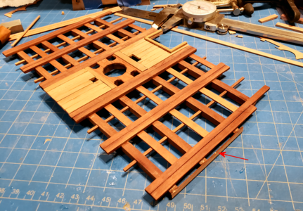
So, I've cheated, and added a 1mm strip to each side of the cross beams of the gun deck, effectively increasing the width of the deck 2mm, which fills the gap at that point. It shouldn't be visible, and also gives me more area to glue when installing the deck. I'll post a pic of the pieces added to the deck, not as an example of what to do, but as an example of what can be done to accommodate errors or problems during the build process:

The wedges here are shown as not tapered, but in fact they were tapered so as to both be able to be hammered tight, and to adjust the perpendicularity of the mast. I decided to make mine tapered vertically, like the actual ones, although tapered more than originally, to make them easier to fit.
I took measurements of the mast (15.6mm in diameter) and the inside of the 12-sided opening for the wedges across flats (20.75mm). and made a layout:

The thickness of the wedges end up just over 2mm, so I decided to use 3mm stock, full thickness at the top and tapered toward the bottom. I used 3x6mm pear from the kit, although I couldn't spare it because I didn't have enough for the decks, but I'll make do. The full 6mm width is close enough to the above drawing's 5.904mm, so can be used as-is.
- I then took a strip of 3x6mm pear about 10" long, marked off in 5/8" increments (the finished overall height I wanted for the wedges) marked from each end toward the middle.
- Put a 15 degree taper on each side. I used a 1x18 vertical belt sander, because I'm lazy, but by hand would be fine. With the table at 90 degrees, I placed my smartphone on it with a bubble level app, and calibrated (reset) it, then moved the table until I had my 15 degrees. (BTW, this is a 12-sided opening, meaning each wedge takes up 360/12 = 30 degrees, so 15 degree slope on each side.) The thinner side should be AWAY from the 5/8" marks so as not to sand them off later.
- Using a 1/2" diameter sanding drum on a vertical drum sander, make the concave portion of the wedge. I was able to hold the 10" wedge reasonably centered on the sanding drum to do this, and the concave area isn't perfect, but good enough.
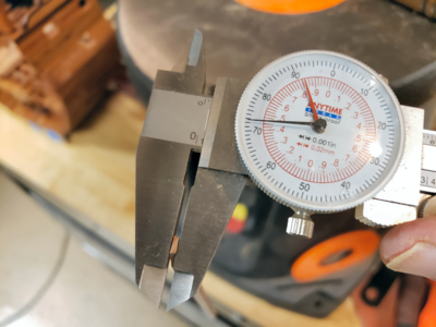
- I then held the strip at about 5 degrees (roughly 1/4" in 3") to the vertical sanding belt, and sanded the end off of the FLAT side to the marked 5/8" line. I checked with a dial caliper that I had roughly the 1.71mm width at the end point, which should result in a thickness at the center vertically of about 2.36mm where it meets the deck.
- I did this to both ends of the strip (the 5/8" marks were for each end), then cut off at the 5/8" line, giving a completed wedge, and started with step 5, doing this until I had made 14 wedges (2 spares).


This photo shows the end of the strip after having the two 15 degree bevels applied and the radius. The radius isn't very visible in this photo, but it's there:

Checking the end thickness prior to cutting off the wedge:

The completed wedge, prior to being cut off the strip:

Completed wedges:

NOTE: Before proceeding with the mast and wedges in the model, MARK THE MAST near its bottom to indicate the side facing the #1 rib on the model. The installed mast will probably NOT fit well if rotated to any other position.
With the lower gun deck, to which the mast attaches, temporarily held in place, I add two wedges opposite each other:

Do NOT glue wedges in place during this adjustment operation.
I checked the dimension from the mast to the inner side of the hull on each side to be sure it's vertical side-to-side. Wedges are adjusted (pull one out slightly, push the other in) to get it centered:

Sorry. Didn't notice I'd focused on the wrong area.
Continue by installing wedges toward the front and back:

As it was hard to determine vertical on the model this way, I eyed it as being parallel to the hull ribs.
Continue around placing wedges, without gluing, until it's how you want it:

After you're happy with the placement, take one wedge out at a time, super glue the curved side toward the mast, and replace it. do this for all the wedges. After the glue has dried, you can remove the mast, with wedges attached. If one or more fall off, you probably missed gluing them; replace the mast and reglue any loose wedge:


The right photo above shows some trimming and rounding done to the top of the wedges (above the deck). Don't touch the flat areas that contact the deck.
In place, the mast fits quite snuggly, yet is easily removed, and can be permanently glued in place later when desired. BTW, I placed a brass pin centered in the bottom of the mast to more precisely locate the bottom of the mast.

I think it looks pretty good and definitely holds the mast securely.
Note that there are gaps, etc. in my mast support; I used the wrong dimensions when making the strip width, and then when doing a preliminary fit, the wedges seemed too wide, so reduced the width of them. I shouldn't have. The gaps resulted. But by then they were attached to the mast, and I didn't feel like doing it over. Chalk it up to another mistake.
Speaking of mistakes, my constructed ribs have always been a bit wide at the top. I didn't think it was a problem, because they easily flexed 1/2" or so. But as I continued to work on the hull, of course it got stiffer and stiffer. And installing the orlop deck means it's very difficult to push the sides in on higher decks.
So, I've cheated, and added a 1mm strip to each side of the cross beams of the gun deck, effectively increasing the width of the deck 2mm, which fills the gap at that point. It shouldn't be visible, and also gives me more area to glue when installing the deck. I'll post a pic of the pieces added to the deck, not as an example of what to do, but as an example of what can be done to accommodate errors or problems during the build process:

Last edited:
Your mast wedges are very well prepared, but I think, that you made yourself more work than necessary.I decided to attack the mast connection and support on the lower gun deck with its wedges next. The installation is shown in the instructions like this:
View attachment 292729
The wedges here are shown as not tapered, but in fact they were tapered so as to both be able to be hammered tight, and to adjust the perpendicularity of the mast. I decided to make mine tapered vertically, like the actual ones, although tapered more than originally, to make them easier to fit.
I took measurements of the mast (15.6mm in diameter) and the inside of the 12-sided opening for the wedges across flats (20.75mm). and made a layout:
View attachment 292736
The thickness of the wedges end up just over 2mm, so I decided to use 3mm stock, full thickness at the top and tapered toward the bottom. I used 3x6mm pear from the kit, although I couldn't spare it because I didn't have enough for the decks, but I'll make do. The full 6mm width is close enough to the above drawing's 5.904mm, so can be used as-is.
Visually, the steps of shaping the last 5/8" of the strip are shown here:
- I then took a strip of 3x6mm pear about 10" long, marked off in 5/8" increments (the finished overall height I wanted for the wedges) marked from each end toward the middle.
- Put a 15 degree taper on each side. I used a 1x18 vertical belt sander, because I'm lazy, but by hand would be fine. With the table at 90 degrees, I placed my smartphone on it with a bubble level app, and calibrated (reset) it, then moved the table until I had my 15 degrees. (BTW, this is a 12-sided opening, meaning each wedge takes up 360/12 = 30 degrees, so 15 degree slope on each side.) The thinner side should be AWAY from the 5/8" marks so as not to sand them off later.
- Using a 1/2" diameter sanding drum on a vertical drum sander, make the concave portion of the wedge. I was able to hold the 10" wedge reasonably centered on the sanding drum to do this, and the concave area isn't perfect, but good enough.
- I then held the strip at about 5 degrees (roughly 1/4" in 3") to the vertical sanding belt, and sanded the end off of the FLAT side to the marked 5/8" line. I checked with a dial caliper that I had roughly the 1.71mm width at the end point, which should result in a thickness at the center vertically of about 2.36mm where it meets the deck.
- I did this to both ends of the strip (the 5/8" marks were for each end), then cut off at the 5/8" line, giving a completed wedge, and started with step 5, doing this until I had made 14 wedges (2 spares).
View attachment 292748 View attachment 292750 View attachment 292751 View attachment 292752
This photo shows the end of the strip after having the two 15 degree bevels applied and the radius. The radius isn't very visible in this photo, but it's there:
View attachment 292774
Checking the end thickness prior to cutting off the wedge:
View attachment 292776
The completed wedge, prior to being cut off the strip:
View attachment 292775
Completed wedges:
View attachment 292778
NOTE: Before proceeding with the mast and wedges in the model, MARK THE MAST near its bottom to indicate the side facing the #1 rib on the model. The installed mast will probably NOT fit well if rotated to any other position.
With the lower gun deck, to which the mast attaches, temporarily held in place, I add two wedges opposite each other:
View attachment 292779
Do NOT glue wedges in place during this adjustment operation.
I checked the dimension from the mast to the inner side of the hull on each side to be sure it's vertical side-to-side. Wedges are adjusted (pull one out slightly, push the other in) to get it centered:
View attachment 292780
Sorry. Didn't notice I'd focused on the wrong area.
Continue by installing wedges toward the front and back:
View attachment 292781
As it was hard to determine vertical on the model this way, I eyed it as being parallel to the hull ribs.
Continue around placing wedges, without gluing, until it's how you want it:
View attachment 292782
After you're happy with the placement, take one wedge out at a time, super glue the curved side toward the mast, and replace it. do this for all the wedges. After the glue has dried, you can remove the mast, with wedges attached. If one or more fall off, you probably missed gluing them; replace the mast and reglue any loose wedge:
View attachment 292783 View attachment 292784
The right photo above shows some trimming and rounding done to the top of the wedges (above the deck). Don't touch the flat areas that contact the deck.
In place, the mast fits quite snuggly, yet is easily removed, and can be permanently glued in place later when desired. BTW, I placed a brass pin centered in the bottom of the mast to more precisely locate the bottom of the mast.
View attachment 292785
I think it looks pretty good and definitely holds the mast securely.
Note that there are gaps, etc. in my mast support; I used the wrong dimensions when making the strip width, and then when doing a preliminary fit, the wedges seemed too wide, so reduced the width of them. I shouldn't have. The gaps resulted. But by then they were attached to the mast, and I didn't feel like doing it over. Chalk it up to another mistake.
Speaking of mistakes, my constructed ribs have always been a bit wide at the top. I didn't think it was a problem, because they easily flexed 1/2" or so. But as I continued to work on the hull, of course it got stiffer and stiffer. And installing the orlop deck means it's very difficult to push the sides in on higher decks.
So, I've cheated, and added a 1mm strip to each side of the cross beams of the gun deck, effectively increasing the width of the deck 2mm, which fills the gap at that point. It shouldn't be visible, and also gives me more area to glue when installing the deck. I'll post a pic of the pieces added to the deck, not as an example of what to do, but as an example of what can be done to accommodate errors or problems during the build process:
View attachment 292787
I mean the tapering before the installation
When you make first the ring with untapered segments and sand / taper afterwards the outside of the ring
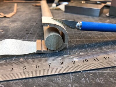
Thanks, Uwe, I appreciate your feedback. That method is certainly better looking and no doubt easier, but I liked the idea of adjusting the level of the mast as I was installing it, as was done on the real ship, since I had already constructed the gun deck with the 12-sided opening. I think you made your own opening (3mm thick which is what the included one /should/ have been), and mounted it during construction of the deck, which is certainly a great way.
There are quite a number of things I'd have done differently, given the chance to do it again. ;-)
There are quite a number of things I'd have done differently, given the chance to do it again. ;-)
I decided to put together the two 18-pound guns for the lower gun deck, to help determine where I needed to have planking. The piece of 3mm diameter brass rod the manufacturer included for the two trunnions was 22mm long, while I needed at least 13mm for each trunnion; I had a longer length on hand that suited well. A 50mm length of 2mm diameter brass rod was included for the other 4 guns, which leaves only 12.5mm length for each gun, ignoring saw kerf, but I have some more of that too, so no problem there.
I started assembly in the suggested manner, cementing the front axtree and transom to the stool bed (is the long piece connecting the two axtrees called a stool bed on a French gun? I'm more familiar with English guns, which don't have a piece connecting them, but usually just a bolster and stool bed over the rear axtree.):
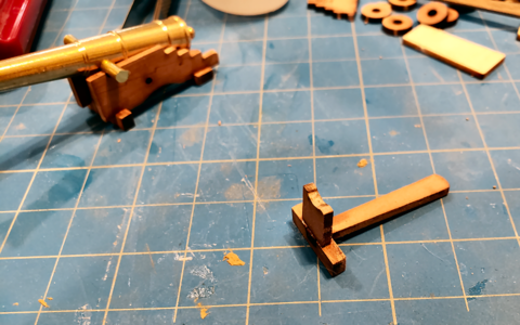
And then adding the side brackets, rear axtree, etc. using a template to provide proper spacing and angle of the brackets:
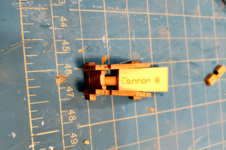
As can be seen above, the template would force the brackets further apart at the front of the carriage than the transom is wide, leaving a gap, which can't be there. The brackets seemed far enough apart given the transom for spacing, and seemed to fit the barrel width okay, so I went with it. The template for the smaller guns seems too wide too, compared to the transom.
I then wondered about the barrel lengths and carriage sizes. It is typical in kit ship models to use readily available barrels (commonly brass as in this case), and the barrels looked long to me, and to be honest, the carriages short. So I took Boudriot's information and scale drawings on the guns on the Bonhomme Richard and compared them to what is included in the model.
For those who would like to do their own comparison, the image below is taken directly from Boudriot's drawing, enhanced to be more clear and to have color, and I've added one dimension to it:
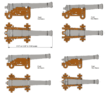
If you print the above image, manually scaled so that the 9' line shown above is exactly 2.25" long, then the drawings will be in the same scale as this kit, 1/48, and gun parts can be compared.
I've scaled dimensions from the above drawing, and compared it with equivalent actual kit measurements (retired Engineer here, remember?), coming up with the following spreadsheet (never pass up the opportunity to make a spreadsheet, graph or 3D drawing):
Comparison of Boudriot's Gun Drawings versus Included with Kit
I've also photographed the above image with the kit components, so you can get an idea of the sizes:
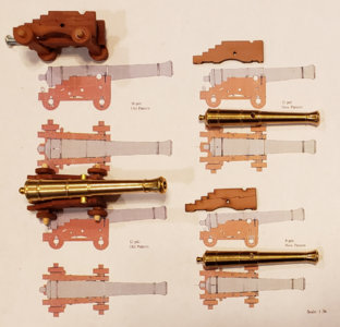
Basically, the 18-pounders are pretty close to the correct size. The included 12-pounder barrels are between the Old and New design length, which isn't bad. The 8-pounder barrels are a good bit longer than they should be, and unfortunately, are most visible, being on the top deck.
As to the carriages, the 18-pounder's carriage is actually very close to correct. The 12-pounder's isn't too bad, but the 8-pounder's carriage is 22% too long (of course the 8-pounder's barrel is 15% too long, so the ratio isn't that different).
If the barrels weren't of nice quality brass, I'd have my son make new ones with his 3D printer, but I'll probably just keep them (after all that - yeah!). I do think I will shorten the 8-pounder carriages/brackets a bit, and eliminate one of the steps in the brackets, to be a bit closer to true. Too bad I can't knock 1/4" off the length of the barrels too.
I started assembly in the suggested manner, cementing the front axtree and transom to the stool bed (is the long piece connecting the two axtrees called a stool bed on a French gun? I'm more familiar with English guns, which don't have a piece connecting them, but usually just a bolster and stool bed over the rear axtree.):

And then adding the side brackets, rear axtree, etc. using a template to provide proper spacing and angle of the brackets:

As can be seen above, the template would force the brackets further apart at the front of the carriage than the transom is wide, leaving a gap, which can't be there. The brackets seemed far enough apart given the transom for spacing, and seemed to fit the barrel width okay, so I went with it. The template for the smaller guns seems too wide too, compared to the transom.
I then wondered about the barrel lengths and carriage sizes. It is typical in kit ship models to use readily available barrels (commonly brass as in this case), and the barrels looked long to me, and to be honest, the carriages short. So I took Boudriot's information and scale drawings on the guns on the Bonhomme Richard and compared them to what is included in the model.
For those who would like to do their own comparison, the image below is taken directly from Boudriot's drawing, enhanced to be more clear and to have color, and I've added one dimension to it:

If you print the above image, manually scaled so that the 9' line shown above is exactly 2.25" long, then the drawings will be in the same scale as this kit, 1/48, and gun parts can be compared.
I've scaled dimensions from the above drawing, and compared it with equivalent actual kit measurements (retired Engineer here, remember?), coming up with the following spreadsheet (never pass up the opportunity to make a spreadsheet, graph or 3D drawing):
Comparison of Boudriot's Gun Drawings versus Included with Kit
| Gun Barrel Length, Muzzle Face to after side of Base-Ring | |||||
| Gun Size | Actual ft | Scale in | Actual in | Equiv ft ' | % if Correct |
| 18-Pounder | 9.00 | 2.25 | 2.36 | 9.45 | 105% |
| 12-Pounder New | 7.50 | 1.88 | 1.97 | 7.86 | 105% |
| 12-Pounder Old | 8.50 | 2.13 | 1.97 | 7.86 | 93% |
| 8-Pounder | 6.83 | 1.71 | 1.97 | 7.86 | 115% |
| Gun Barrel Diameter over Muzzle Mouldings | |||||
| Gun Size | Actual ft | Scale in | Actual in | Equiv ft ' | % if Correct |
| 18-Pounder | 1.21 | 0.303 | 0.308 | 1.23 | 102% |
| 12-Pounder New | 1.10 | 0.275 | 0.261 | 1.04 | 95% |
| 12-Pounder Old | 1.01 | 0.253 | 0.261 | 1.04 | 103% |
| 8-Pounder | 1.00 | 0.250 | 0.261 | 1.04 | 104% |
| Gun Barrel Diameter over Base-Ring | |||||
| Gun Size | Actual ft | Scale in | Actual in | Equiv ft ' | % if Correct |
| 18-Pounder | 1.54 | 0.385 | 0.391 | 1.56 | 102% |
| 12-Pounder New | 1.35 | 0.338 | 0.331 | 1.32 | 98% |
| 12-Pounder Old | 1.32 | 0.330 | 0.331 | 1.32 | 100% |
| 8-Pounder | 1.20 | 0.300 | 0.331 | 1.32 | 110% |
| Gun Barrel Diameter at Trunnion | |||||
| Gun Size | Actual ft | Scale in | Actual in | Equiv ft ' | % if Correct |
| 18-Pounder | 1.25 | 0.313 | 0.312 | 1.25 | 100% |
| 12-Pounder New | 1.15 | 0.288 | 0.263 | 1.05 | 91% |
| 12-Pounder Old | 1.23 | 0.308 | 0.263 | 1.05 | 86% |
| 8-Pounder | 0.99 | 0.248 | 0.263 | 1.05 | 106% |
| Carriage Length at Brackets | |||||
| Gun Size | Actual ft | Scale in | Actual in | Equiv ft ' | % if Correct |
| 18-Pounder | 5.29 | 1.323 | 1.364 | 5.46 | 103% |
| 12-Pounder New | 4.76 | 1.190 | 1.265 | 5.06 | 106% |
| 12-Pounder Old | 4.77 | 1.193 | 1.265 | 5.06 | 106% |
| 8-Pounder | 4.16 | 1.040 | 1.265 | 5.06 | 122% |
| Barrel Length to Carriage Length Ratio | |||||
| Gun Size | Actual Ratio | Model Ratio | % of Correct | ||
| 18-Pounder | 1.70 | 1.73 | 102% | ||
| 12-Pounder New | 1.58 | 1.55 | 99% | ||
| 12-Pounder Old | 1.78 | 1.55 | 87% | ||
| 8-Pounder | 1.64 | 1.55 | 95% |
I've also photographed the above image with the kit components, so you can get an idea of the sizes:

Basically, the 18-pounders are pretty close to the correct size. The included 12-pounder barrels are between the Old and New design length, which isn't bad. The 8-pounder barrels are a good bit longer than they should be, and unfortunately, are most visible, being on the top deck.
As to the carriages, the 18-pounder's carriage is actually very close to correct. The 12-pounder's isn't too bad, but the 8-pounder's carriage is 22% too long (of course the 8-pounder's barrel is 15% too long, so the ratio isn't that different).
If the barrels weren't of nice quality brass, I'd have my son make new ones with his 3D printer, but I'll probably just keep them (after all that - yeah!). I do think I will shorten the 8-pounder carriages/brackets a bit, and eliminate one of the steps in the brackets, to be a bit closer to true. Too bad I can't knock 1/4" off the length of the barrels too.
Very good comparison of the kit content and the Boudriot information.
Which version do you plan to build?
When you build the Le Duc de Duras you need guns for every deck, so all three sizes.
when you plan to build the (USS) Bonhomme Richard, than you have to decide, if you want to show her historical correct with the guns on the correct place, or with as much as possible guns, but off course than historical not correct - a question of taste
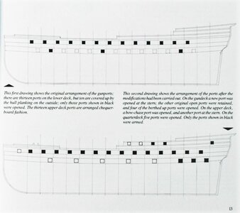
If you build the Bonhomme Richard, than only on one deck of the section model guns are installed - and this were the 12-pdr guns
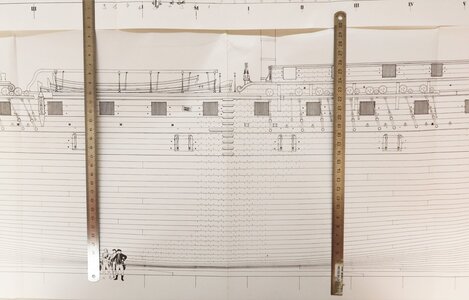
BTW: the drawing of the guns in the Boudriot book are in 1:36, so I guess you adjusted the size of your print to 1:48
Which version do you plan to build?
When you build the Le Duc de Duras you need guns for every deck, so all three sizes.
when you plan to build the (USS) Bonhomme Richard, than you have to decide, if you want to show her historical correct with the guns on the correct place, or with as much as possible guns, but off course than historical not correct - a question of taste

If you build the Bonhomme Richard, than only on one deck of the section model guns are installed - and this were the 12-pdr guns

BTW: the drawing of the guns in the Boudriot book are in 1:36, so I guess you adjusted the size of your print to 1:48
You make a good point, of course, Uwe. I like 100% accuracy when it comes to features, but am willing to move things around when building the cross section. Of course, I plan on using all three sizes, with six guns total, because - well, they look good.Very good comparison of the kit content and the Boudriot information.
Which version do you plan to build?
When you build the Le Duc de Duras you need guns for every deck, so all three sizes.
when you plan to build the (USS) Bonhomme Richard, than you have to decide, if you want to show her historical correct with the guns on the correct place, or with as much as possible guns, but off course than historical not correct - a question of taste
View attachment 293058
If you build the Bonhomme Richard, than only on one deck of the section model guns are installed - and this were the 12-pdr guns
View attachment 293061
BTW: the drawing of the guns in the Boudriot book are in 1:36, so I guess you adjusted the size of your print to 1:48
As to guns on Le Duc de Duras, being designed as a cargo carrier, I actually assumed it had no guns, but its construction allowed them to be added. I've seen no mention of removing or keeping any guns onboard when first given to Jones, only guns be brought onboard.
As to historic accuracy, almost any cross section will have adjustments made so as to show as much information as possible within the cross section length. Only very long sections like Jeronimo has done can hope to accurately portray that area of the ship, yet provide much detail and interest.
Yes, I adjusted the size of my printout to 1:48, but as stated, the main thing is to print it so that the 9' length is 9 scale feet in the selected scale. This could be adjusted either up or down.
Thanks again for your comments and information.
understood and I can fully follow.As to guns on Le Duc de Duras, being designed as a cargo carrier, I actually assumed it had no guns, but its construction allowed them to be added. I've seen no mention of removing or keeping any guns onboard when first given to Jones, only guns be brought onboard.
Only one correction:
Merchant ships had at this time often a lot of guns permanently on board - They had to defend themselfs as much as possible against pirates and the french against english warships.
So the gunports of the french merchant were armed with guns, not all, but a bigger number of the ports.
Here are the data given in the web-page three-decks which are usually very accurate and collected by first and second sources - and the contemporary sources are giving here a very good information
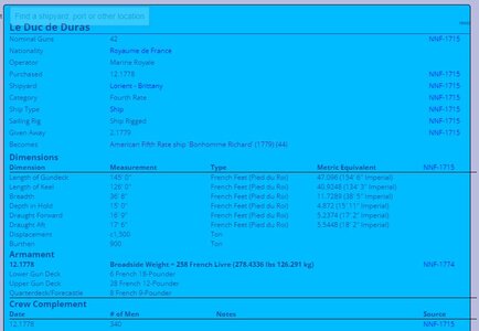
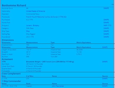
Luc de Duras had a Boradside weight (as merchant) of 258 french LIvre with together 42 guns
the later Bonhomme Richard even slightly less with 240 french livres with 44 guns
French Fourth Rate ship 'Le Duc de Duras' (1778)
French Fourth Rate ship 'Le Duc de Duras' (1778). Dates of service, name changes, previous and next incarnations, dimensions, armament, commanders, officers and crewmen, actions, battles, sources
threedecks.org
Since we're discussing naval guns, Boudriot mentions the number of cannon balls provided to the Bonhomme Richard upon her voyage:
420 18# shot of 138mm diameter (0.4528' in diameter)
1966 12# shot of 121mm diameter (0.3970' in diameter)
566 8# shot of 106mm diameter (0.3478' in diameter)
This worked out to very close to 70 shot per gun (the French standard was 60 shot per gun).
I mention this, because I was curious how much storage space the cannon balls would take up, located in the shot locker. The entire shot locker is roughly 7' wide by 3.5' long in the model, or 24.5 square feet. If it is divided into thirds for each size of shot, that would end up just over 8 square feet each.
Now to calculate the volume required for the shot loaded:
Volume of each ball = 4/3*pi*radius^3 or pi/6*Diameter^3. Total volume per size is volume per ball x number of balls. So:
18#: 420 * pi / 6 *.4528^3 / .64= 31.9 cubic feet (divide by 8 to give a 4' high stack of balls)
12#: 1966 * pi / 6 * .397^3 / .64 = 100.64 cubic feet (divide by 8 to give a 12.5' high stack of balls)
8#: 566 * pi / 6 * .3478^3 / .64 = 19.5 cubic feet (divide by 8 to give a 2.4' high stack of balls)
The .64 factor is the "stacking factor" for balls (ranges between .64 and .66) and represents the ratio of ball volume to air volume in a solid stack of balls.
What's all the above about? Well, I was just wondering how the shot locker would have been divided. If in thirds, as has been suggested here, then the 12# balls would fill it all the way to above the orlop deck, as I have shown in my model, but the 18# and 8# stacks would be well down into the hold in height. All in all, they'd be difficult to retrieve from the opening on the orlop deck. So just wondered if it were divided differently, and how they could easily and quickly retrieve the shot when needed.


