Soleil Royal by Heller - an Extensive Modification and Partial Scratch-Build by Hubac’s Historian

I was thinking that maybe certain locations specialized in specific revelations. Maybe the Hudson River would provide help with regard to the galleries. Liberty Park with the galleon. Broadway could be the source of deep insight into making deadeyes. Just thinking out loud here...
Maybe I am not as sophisticated as you two, most of my modelling revelations come to me in the bathROTF:rolleyes:
 
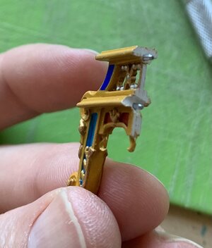
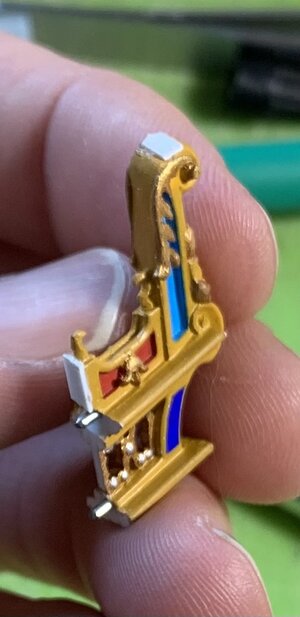
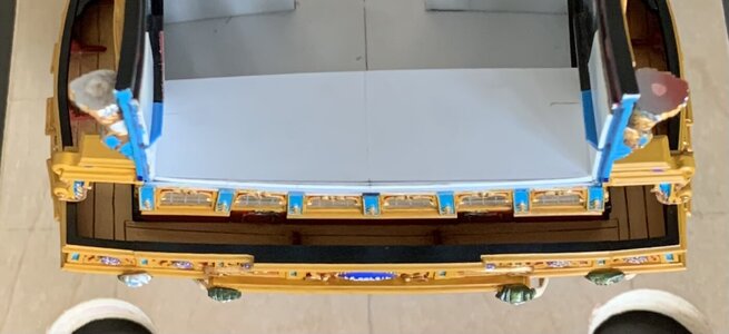
I’ve completed and am in the process of painting the stern archway brackets. The channel standards are coming along, slowly, after a little excise and replacement.

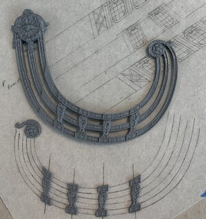
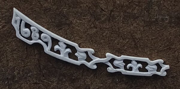
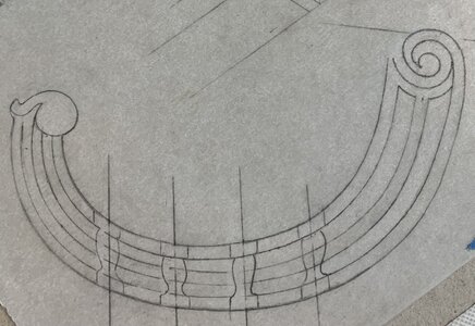
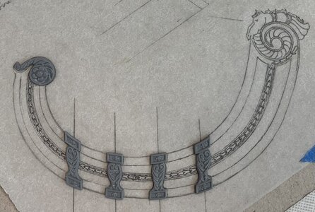
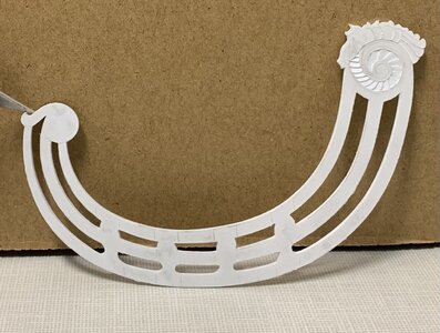
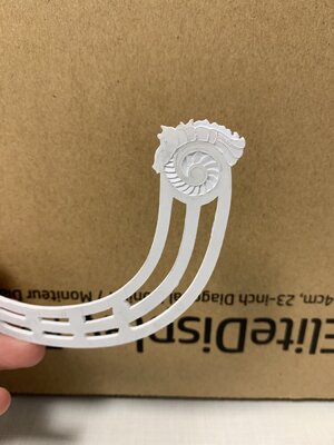
I have continued to tweak and play around with my new headrail design. The bottom rail width still requires a little tweaking, but the symmetry and taper are already an improvement over the stock rails. Here are the carved elements that I can definitely recycle:
0AAA4BFC-9B5A-46AE-9A7E-842A5A3A0E9A.jpeg
When I re-incorporate stock carvings, I like to undercut the carvings with the tip of a #11 blade, in order to give a better sense of relief; the idea is similar to the process of metal chasing brass castings, for example. The carvings end up looking crisper, overall, and it is an easy thing to achieve with backward scrapes of the blade point, heal first.

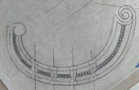
The pilasters have been re-spaced. I wanted them to neatly correspond with either the fleurs of the Xs of the trailboard, but the abbreviated design of the trailboard made that an impossibility.

7B61302F-D43E-4344-AB42-A39066DC111A.jpeg
3FF0E824-7288-44E9-9FF0-F1A5F818BDE5.jpeg
It just occurred to me, as a matter of fact, that I will have to re-check my tentative pilaster layout to ensure that it does not intersect with the run of the gammoning. On the stock kit, this consideration is moot because there are no ‘thwartship supporting timbers that the gammoning must pass between. Here, though, those supports will align with the pilasters.

I have decided that I will design the aft medallion to closely follow the Berain drawing. The stock medallion is nice, but it interferes with the horse and pixie sculptures in ways that are un-tennable.

As always, thank you for your interest and for looking in.
 
The design process continues. After checking against the model, I realized after all, that I would have to shift the front three pilasters aft by about 1/16”. Now the gammoning will pass cleanly between the ‘thwartship supporting timbers.

I took this opportunity to mark the cardboard template for the height of the aft rosette. In doing so, it dawned on me that I could do exactly as Druxey suggested, and make additional room space beneath the headrails. His annoying :p voice kept rattling around my brain, as I kept thinking to myself “you know he’s right!”. In the end, it was a simple matter of lifting the aft rosette until I was satisfied with the spacing.

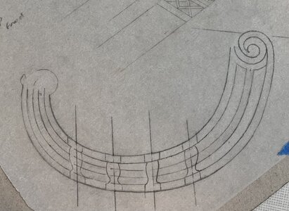
Now that I had determined to copy the Berain design more closely, I did a little more refining of the rail widths, and then set about drawing the aft, scrolled rosette; it is simple-seeming enough, but I spent hours trying to draw this volute. My pointillist-mapping technique for drawing irregular curves looks like this, just before I trace over the dotted line:

FBF071BA-E813-4398-BA63-DDD3F001E44B.jpeg

I thought this looked pretty good until the next day, when I realized that the volute should be as closely centered on the middle rail as possible. More hours were spent drawing and erasing:

050AD963-C6E2-418E-8841-A13A494B57A5.jpeg

This was much better, however, the scroll within the scroll needed a little re-balancing, especially in consideration of the way in which the horse’s snout nestles into this open area:

34692711-FDBC-424A-BEAD-D1F1EDD97C58.jpeg

Okay, now I could start penciling in only the necessary mouldings to help me determine the size of the bellflower garland:

0820E234-78CE-45F9-9774-7BD4383B9BEC.jpeg

I am making small alterations to Berain’s design, as I see sensible and/or necessary; in the original drawing the garland runs all in one direction, aftwards. I have decided to make a transition between the second and third pilasters, so that half the garland runs forward toward the reins of the figurehead.

Here is where the drawing stands, as of now:

5D5B8BF1-F6E5-4C0C-9CA3-362A0C578896.jpeg

At this stage, I can photocopy this drawing and paste a copy to my cardboard template, so that I can take precise measurements of where my pixie figure will fit-in without the whole thing looking un-balanced.

Drawing all of this, is one matter. Figuring out how exactly to apply my layered approach to part-making so that there is the appropriate sense of relief and overlay will take some thought. If that weren’t enough, the headrails bow out, around the beakhead grating, and then reverse inward to tuck-in behind the figurehead. I don’t think heat-bending is the way to go, here. I will, instead, induce these curves over a form, over a period of a few days.

I hope everyone has a happy and safe holiday weekend!

More to follow…
 
Last edited:
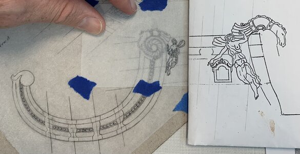
I took measurements off of the model, and transferred them to my drawing, which I had sprayed with hairspray to fix the graphite before proceeding with the pixie figure. I expected to be erasing a lot, and I was correct!

Unfortunately, the hairspray altered the “tooth” of the paper, and I just could not draw clean lines, so I taped an overlay for the pixie. This was helpful, in revising my earlier attempt because I could re-plot elements I wanted to maintain, while making spatial assessments of what needed to be changed.

It took a while to get the proportions of her limbs where I wanted them. You can see, in comparison with the drawing I made at the start of this project, how scaled-down the horse and pixie now are:

B1028F7C-AE32-4D29-B5B0-C594E66F7AF7.jpeg

I am satisfied with all of this, so tonight I will paste a photocopy to a blank of 1/16” styrene sheet, and I will begin making the port headrails.

The horse figure will be integral to the headrails, while the pixie will be a separate part. I expect each headrail side to take a couple of weeks to make, but this is an enjoyable and portable side-project.

As always, thank you for the likes and for looking-in. More to follow!
 
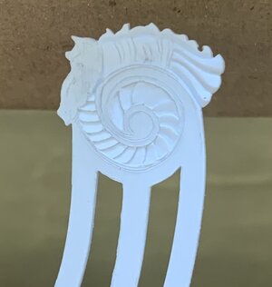
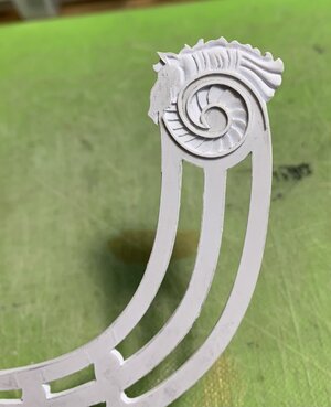
In consideration of Thomas’s request, I’ve been photographing the headrails as I carve the horse ornament. The starting place was to carve the fanned relief in the inner scroll:
EEE67975-8F5A-4009-8D56-1497963DCFF5.jpeg
From there, carving the horse is mostly about establishing levels within the carving. Here, I’ve determined that where the mane meets the horse’s back will be the lowest-depth cut of the carving, my baseline:
CDE94779-8F87-4506-A78C-D3915FFE5C06.jpeg
After undercutting the mane a bit, which helps give dimension, later during the modeling of the mane, I decided to proceed from the tail to snout, as this Roman skirt was an easy thing to understand and model:
32FB36A1-8341-42C3-8F0F-45397AC3BE52.jpeg
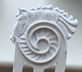
It all proceeds smoothly enough, until the head, which presents some challenges. For the record, I have not done any involved study of horse anatomy. I am merely attempting to hint at the major muscle groups that animate the animal’s jaw and face.

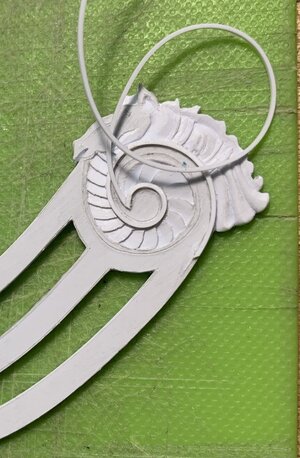
I wanted to experiment with my idea to add the bordering of the headrails. It was easy enough to induce a curl into this square styrene strip (.020) with my finger nail. I anchor the starting point with thin CA, and then I work my way around the scroll, 1/4” by 1/4”, with liquid styrene cement. It turned out about as well as I could have hoped.
F37BD92E-D0A5-4875-8B8E-7FF6C434D54D.jpeg
435EEF3C-273D-4F9D-8B51-101C44B61315.jpeg
Today, I finished up with the modeling of the head and mane.
0BA159AB-0E8D-41E2-8E99-FA06A2F9CA59.jpeg
I still need to add a few applied “buttons” to the two bands that wrap around the horse’s body, but this is a simple thing. It is not an anatomically perfect study, but there is shape and movement that will catch the light and create shadows when painted.

In other news, I have installed the pass-through archways. Because boxwood carvings will sit upon these, I wanted to ensure that they were very securely affixed. After much fitting and strategic scraping of paint, I fit two pins (from a paper clip) into each bracket:
7C982A45-1FF8-47C0-B1B2-ECD32FD21935.jpeg
CC00947C-BDDF-43AE-AC90-49052CFBB824.jpeg
The plan was to glue these in using CA in the sections where the pins are, and liquid styrene cement in-between and at the foot.

I got the correct rake and alignment for the port side, on the first try. There were, however, a pair of gaps that needed filling for a secure welded bond:
796EBA15-FFA3-4868-81E7-8F864CB2A5AA.jpeg
I added styrene pads to the foot and below the lower pin and then faired these to fit seamlessly.

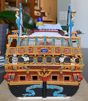
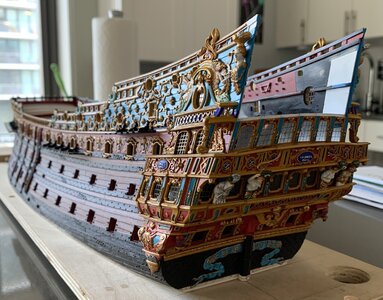
With these brackets in place, my conception of the way Berain’s stern relates to these quarter galleries can be clearly understood:
0CFA3157-4EE2-4F0D-B069-68316284FD6E.jpeg
F7D49669-D120-49FA-A5F8-52613D74896D.jpeg
As a side note: it was really challenging to get the foot of each bracket to align with the pilaster of the gallery bulwark beneath it. The starboard side is acceptable, but the port side (showing the merely acceptable side) came out perfectly:
445A4686-06A5-42D9-BF9F-5D38603E49B9.jpeg
I also wanted the brackets to follow the round-up of the stern, so their in-board surfaces had to be beveled, accordingly:
428C057C-BADA-4C51-A192-943015D86FB6.jpeg
E3E1558B-8FB2-4666-A970-F65689DB84F1.jpeg
37A2860E-E4C9-4D06-A1D8-5828BF11A8FA.jpeg
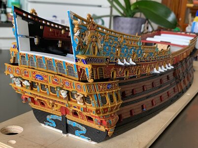
In natural light, this is a very accurate reflection of my colors. Presently, I continue to do all of the necessary touchups, distress washing (not applied to brackets yet, in these pictures), and blackening of the upper main wales and channels, on the starboard side.

My least favorite aspect of this build is attempting to cut super-clean lines directly onto the model. The plywood base is a tremendous asset for these circumstances, but it is always awkward and difficult. Here, my line began to waver, after I had been at it for a few hours:
FCF4C158-8DB2-4107-AFFA-CD8F5A849058.jpeg
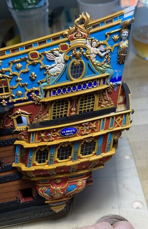
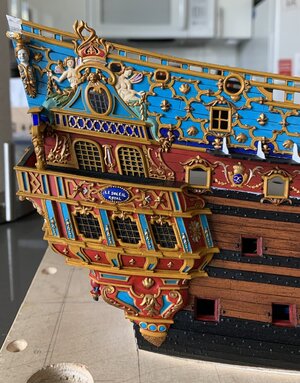
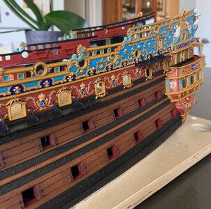
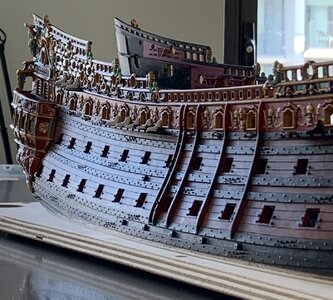
The back and forth process of revision is on-going. The Heller kit has many flaws, but I do think it is fair to say that they get the aft sheer, pretty close to the mark:
892C3BD4-16DC-4C7D-9A35-382D8FFD7D03.jpeg
More to follow!
 
Fabulous Marc.The last photo really shows off her lines.I will be interested how you make the uppermost little gunports work in view of the height difference between the two, relative to the deck support ledge.
 
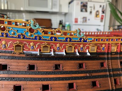
Interesting you should mention that, Nigel. I think my answer to this problem is to arm the forward circular port and the first octagonal port for my 4 poop guns. The aft octagonal port would be in the lower officer quarters, so it would be un-armed. This is one of those compromise items, where inclusion of the two octagonal ports was a nice call-back to the original drawing, but for practical purposes, I was always going to arm that circular port. You are right to point out the discrepancy in barrel heights.
 
In consideration of Thomas’s request, I’ve been photographing the headrails as I carve the horse ornament. The starting place was to carve the fanned relief in the inner scroll:
View attachment 313199
From there, carving the horse is mostly about establishing levels within the carving. Here, I’ve determined that where the mane meets the horse’s back will be the lowest-depth cut of the carving, my baseline:
View attachment 313198
After undercutting the mane a bit, which helps give dimension, later during the modeling of the mane, I decided to proceed from the tail to snout, as this Roman skirt was an easy thing to understand and model:
View attachment 313197
It all proceeds smoothly enough, until the head, which presents some challenges. For the record, I have not done any involved study of horse anatomy. I am merely attempting to hint at the major muscle groups that animate the animal’s jaw and face.

I wanted to experiment with my idea to add the bordering of the headrails. It was easy enough to induce a curl into this square styrene strip (.020) with my finger nail. I anchor the starting point with thin CA, and then I work my way around the scroll, 1/4” by 1/4”, with liquid styrene cement. It turned out about as well as I could have hoped.
View attachment 313196
View attachment 313195
Today, I finished up with the modeling of the head and mane.
View attachment 313194
I still need to add a few applied “buttons” to the two bands that wrap around the horse’s body, but this is a simple thing. It is not an anatomically perfect study, but there is shape and movement that will catch the light and create shadows when painted.

In other news, I have installed the pass-through archways. Because boxwood carvings will sit upon these, I wanted to ensure that they were very securely affixed. After much fitting and strategic scraping of paint, I fit two pins (from a paper clip) into each bracket:
View attachment 313201
View attachment 313202
The plan was to glue these in using CA in the sections where the pins are, and liquid styrene cement in-between and at the foot.

I got the correct rake and alignment for the port side, on the first try. There were, however, a pair of gaps that needed filling for a secure welded bond:
View attachment 313200
I added styrene pads to the foot and below the lower pin and then faired these to fit seamlessly.

With these brackets in place, my conception of the way Berain’s stern relates to these quarter galleries can be clearly understood:
View attachment 313188
View attachment 313189
As a side note: it was really challenging to get the foot of each bracket to align with the pilaster of the gallery bulwark beneath it. The starboard side is acceptable, but the port side (showing the merely acceptable side) came out perfectly:
View attachment 313190
I also wanted the brackets to follow the round-up of the stern, so their in-board surfaces had to be beveled, accordingly:
View attachment 313192
View attachment 313193
View attachment 313191
In natural light, this is a very accurate reflection of my colors. Presently, I continue to do all of the necessary touchups, distress washing (not applied to brackets yet, in these pictures), and blackening of the upper main wales and channels, on the starboard side.

My least favorite aspect of this build is attempting to cut super-clean lines directly onto the model. The plywood base is a tremendous asset for these circumstances, but it is always awkward and difficult. Here, my line began to waver, after I had been at it for a few hours:
View attachment 313187
The back and forth process of revision is on-going. The Heller kit has many flaws, but I do think it is fair to say that they get the aft sheer, pretty close to the mark:
View attachment 313186
More to follow!
Once again stunning workmanship Marc,

Your SR is certainly a feast for the eyes.

Cheers,
Stephen.
 
As always Stephen and Paul, thank you! Paul, yes, the model is good, but that has much less to do with greatness than it does my OCD. The model should be good because I have poured an insane number of hours into it. I do appreciate the thought, though. Maybe I should look into getting a life, huh :rolleyes:
 
As always Stephen and Paul, thank you! Paul, yes, the model is good, but that has much less to do with greatness than it does my OCD. The model should be good because I have poured an insane number of hours into it. I do appreciate the thought, though. Maybe I should look into getting a life, huh :rolleyes:
There are worse (and more dangerous) diversions... I think you're in a good place.
 
Interesting you should mention that, Nigel. I think my answer to this problem is to arm the forward circular port and the first octagonal port for my 4 poop guns. The aft octagonal port would be in the lower officer quarters, so it would be un-armed. This is one of those compromise items, where inclusion of the two octagonal ports was a nice call-back to the original drawing, but for practical purposes, I was always going to arm that circular port. You are right to point out the discrepancy in barrel heights.
That makes good sense, you can always glaze the aftermost ports to further your reasoning;)
 
In consideration of Thomas’s request, I’ve been photographing the headrails as I carve the horse ornament. The starting place was to carve the fanned relief in the inner scroll:
View attachment 313199
From there, carving the horse is mostly about establishing levels within the carving. Here, I’ve determined that where the mane meets the horse’s back will be the lowest-depth cut of the carving, my baseline:
View attachment 313198
After undercutting the mane a bit, which helps give dimension, later during the modeling of the mane, I decided to proceed from the tail to snout, as this Roman skirt was an easy thing to understand and model:
View attachment 313197
It all proceeds smoothly enough, until the head, which presents some challenges. For the record, I have not done any involved study of horse anatomy. I am merely attempting to hint at the major muscle groups that animate the animal’s jaw and face.

I wanted to experiment with my idea to add the bordering of the headrails. It was easy enough to induce a curl into this square styrene strip (.020) with my finger nail. I anchor the starting point with thin CA, and then I work my way around the scroll, 1/4” by 1/4”, with liquid styrene cement. It turned out about as well as I could have hoped.
View attachment 313196
View attachment 313195
Today, I finished up with the modeling of the head and mane.
View attachment 313194
I still need to add a few applied “buttons” to the two bands that wrap around the horse’s body, but this is a simple thing. It is not an anatomically perfect study, but there is shape and movement that will catch the light and create shadows when painted.

In other news, I have installed the pass-through archways. Because boxwood carvings will sit upon these, I wanted to ensure that they were very securely affixed. After much fitting and strategic scraping of paint, I fit two pins (from a paper clip) into each bracket:
View attachment 313201
View attachment 313202
The plan was to glue these in using CA in the sections where the pins are, and liquid styrene cement in-between and at the foot.

I got the correct rake and alignment for the port side, on the first try. There were, however, a pair of gaps that needed filling for a secure welded bond:
View attachment 313200
I added styrene pads to the foot and below the lower pin and then faired these to fit seamlessly.

With these brackets in place, my conception of the way Berain’s stern relates to these quarter galleries can be clearly understood:
View attachment 313188
View attachment 313189
As a side note: it was really challenging to get the foot of each bracket to align with the pilaster of the gallery bulwark beneath it. The starboard side is acceptable, but the port side (showing the merely acceptable side) came out perfectly:
View attachment 313190
I also wanted the brackets to follow the round-up of the stern, so their in-board surfaces had to be beveled, accordingly:
View attachment 313192
View attachment 313193
View attachment 313191
In natural light, this is a very accurate reflection of my colors. Presently, I continue to do all of the necessary touchups, distress washing (not applied to brackets yet, in these pictures), and blackening of the upper main wales and channels, on the starboard side.

My least favorite aspect of this build is attempting to cut super-clean lines directly onto the model. The plywood base is a tremendous asset for these circumstances, but it is always awkward and difficult. Here, my line began to waver, after I had been at it for a few hours:
View attachment 313187
The back and forth process of revision is on-going. The Heller kit has many flaws, but I do think it is fair to say that they get the aft sheer, pretty close to the mark:
View attachment 313186
More to follow!
Love looking at those side photos showing the details, it is magnificent.
 
In a couple of days, I will embark upon my first honest-to-goodness vacation in about 12 years. Sure, we’ve taken family trips, but we have never been to any place quite as breathtaking as Hawaii. To say that we are excited is an understatement for all-time!

I’ve taken things with the model to a nice break-point, to walk away and not obsess about it for a little while. I finished up the paint re-touches on the starboard side. While I will continue to modulate the walnut wash, right up to the clearcoat stage, I’m pretty happy with the ship’s sea-legs appearance.

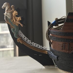
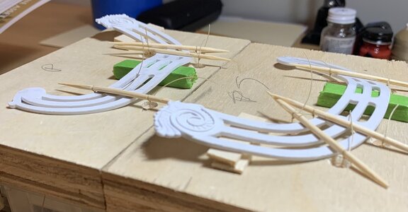
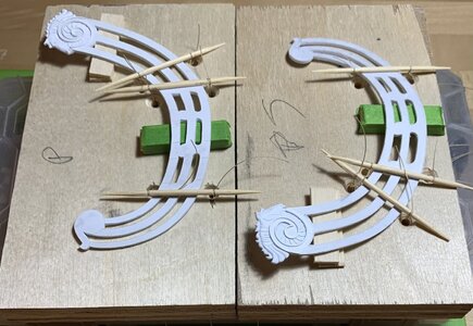
I have both headrails to the point where I need to induce a series of curves, before I fit them to the ship and then go whole-hog on the decorative detailing. I’ve decided that the best approach would be to set these up in mirrored forms, and allow them to sit in my Eastern exposure window, while I’m away. The sheet plastic these are made from is relatively supple, and I think they should relax into these shapes fairly well, with the ability to tweak their final shape by hand.

654CA004-BFF6-43B9-8A1B-D6FB76801811.jpeg
AF17F4D1-9B9F-4314-B267-B29FCAE252DA.jpeg

Per David’s suggestion, I performed a light rhinoplasty on my horseheads, and think that these now look much better. I appreciate the heads’up!

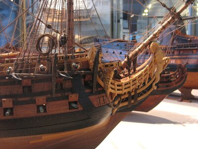
My plan for the head is pretty ambitious:p, as I will attempt to create a properly framed and cambered head-grating that also follows the upward sweep of the headrails. What I’m aiming for is pretty well illustrated in Marc Yeu’s photo of Frolich’s L’Ambiteaux:

F217E179-713E-4A31-AE1A-D3BDC06439CF.jpeg

I will add additional seats of ease, just forward of the turrets.

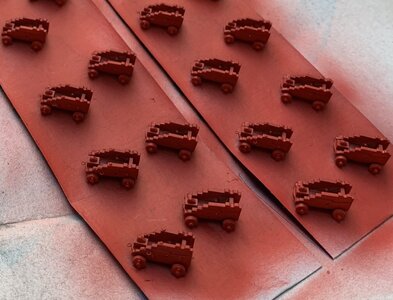
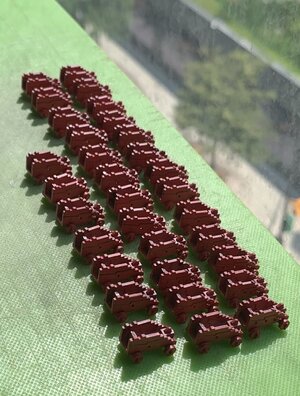
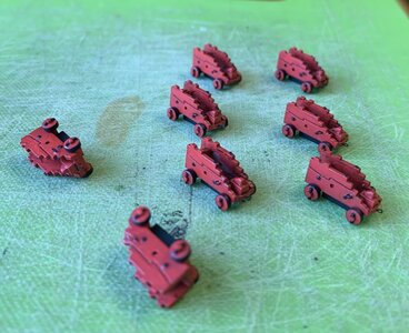
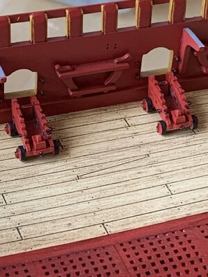
While I don’t need them anytime immediately soon, I thought it might be nice to complete the detailing and begin painting the gun carriages for the main deck guns.

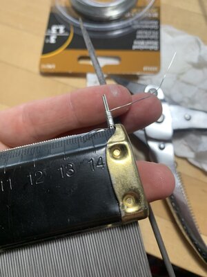
I attempted, in vain, to create these open hooks the French used for the haul-in tackles. I just couldn’t get the scale or shape right, and I could not manage to get them to set properly without making a mess of CA glue:

D7B396A3-B9FC-45C8-BB99-A30B2C4F88E1.jpeg

I thought that if I flattened the back face with a file, I’d have enough of a glue surface to set these onto the carriages.

7D674222-32B1-4DFB-985F-A562EDB6CE6F.jpeg
963EA5DD-D61C-4F22-977E-44085FACC883.jpeg

In the end, I just didn’t think they looked good, so I abandoned them for the English practice of eye-bolts, which I found much easier to keep neat and in-scale:

01C69FC2-F274-4F2E-B995-3E742BE0505A.jpeg

I have only bothered to super-detail the sixteen waist guns that you have any possibility of seeing. These will be the only guns that I rig on the main deck.

A667137E-942A-4BBB-963B-0C6159EFED6E.jpeg
C987FC16-D3B2-4DAC-8001-5F4D2E07A0FB.jpeg

I have made a few more carriages than I need here, but I may mount a pair of carriages (sans barrels) behind the first vestigial main deck “windows” of the amortisement, as this would likely have been an additional space for adding artillery, when needed. No one will ever see it, but I will know they are there.

After walnut wash and blacking the iron bits, they look like this:

1287F1F4-5651-474D-9637-A2679C69B000.jpeg

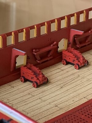
I’ve blacked-out the styrene under mounts that are really my attachment point to the deck. On the ship:

45C5B46A-33F5-4197-9A9C-4FE0E9A8A9E3.jpeg
619F8719-D7BA-4358-BCBB-99A02D466F9C.jpeg

You may recall (way too long of a build log!) that these carriages are really the stock middle deck carriages. After manually scaling-up the lower and middle deck batteries with 1/32” inserts, I realized I could just bump the remaining calibers up a deck and achieve a satisfying increase in scale without too much of a hassle.

As always many thanks to my benefactors on this build who have supplied me with a wealth of spare parts from which to draw upon. The way this has all come together would not be possible without your generous contributions!

As ever, thank you for your continued interest, and I will see you all soon. More to follow..
 
Last edited:
Back
Top