
Mullions are brilliant! How did you create the scribe?

-

SUBSCRIBE TO SHIPS IN SCALE TODAY!
The beloved Ships in Scale Magazine is back and charting a new course for 2026!
Discover new skills, new techniques, and new inspirations in every issue.
NOTE THAT OUR NEXT ISSUE WILL BE July/August 2026 -

Win a Free Custom Engraved Brass Coin!!!
As a way to introduce our brass coins to the community, we will raffle off a free coin during the month of August. Follow link ABOVE for instructions for entering.
You are using an out of date browser. It may not display this or other websites correctly.
You should upgrade or use an alternative browser.
You should upgrade or use an alternative browser.
Soleil Royal by Heller - an Extensive Modification and Partial Scratch-Build by Hubac’s Historian
- Thread starter Hubac’s Historian
- Start date
- Watchers 85
-
- Tags
- 1689 heller hubac refit soleil royal

Thank you, Paul! Super easy, actually -
while the paper design is still craft-glued to the acetate, I make a few light scoring cuts with a number 11 blade against a steel rule. I take care to also make somewhat oversize border scores for each pane, so that I have a little glue surface, later.
Then, I soak the acetate to remove the paper and craft glue residue. Now, I come back to each mullion line with the steel rule and the #11, but this time I take 3-4 moderate pressure engraving passes with the back side of the blade.
I should mention that the acetate I’m using is .030 thickness, so there is plenty of latitude for a deep scribe that will hold the paint well.
The artist tube acrylic then wipes on and into the engraving, and I immediately wipe off the surface excess with cotton t-shirt scraps wrapped over a q-tip swap.
The only tricky part of all of this is ensuring that your blade doesn’t track away from the ruler during the engraving process.
Last edited:
Once again stunning work Marc,These window banks are incredibly labor-intensive, but the process of making them has been very enjoyable for me. What I am doing, here, essentially mirrors what Tanneron did for the sterns of his models. The damaged stern of L’Agreable illustrates how his windows are all pierced into one plate, as seen with the lower bank of windows:
View attachment 300694
Considering the density of detail in such a small space, this method seems far easier than framing each individual window. Getting all of the elements (window frames and pilasters to flow harmoniously would, otherwise be quite difficult.
As I have done previously, I add window backstops to the bulkheads as added insurance that the windows can’t drop out of their frames, if the CA bonds should ever fail:
View attachment 300688
I remain indebted to Druxey for showing me how to make really good acetate windows by simply scribing the mullions into the acetate, and then filling those engravings with medium grey acrylic paint:
View attachment 300687
It really is simple and it just looks so much better than anything else, at scale.
Of course, I will next plank-in beneath the windows, but I am pleased with how the stern is rising:
View attachment 300686
One detail that isn’t so apparent now, but will become so after planking, is the chamfer I filed into the door sides; this chamfer will create a shadow relief that will more clearly delineate the door opening. For the door handles, I recycled a pair of my frieze scrolls, which had the right shape and were sized closely enough.
The round-up really helps to minimize the warped geometry of my stern:
View attachment 300689
At this stage, it is becoming more apparent how the increase in hull-width has established a more ship-like impression of a stable gun platform:
View attachment 300685
This is quite a difference from the stock kit.
So, I will plank and paint beneath the windows, install the balcony bulwark, and create the cap-rail for the balcony bulwarks. I will then take a break from the stern so that I can focus on finishing certain details.
I need to paint and install the starboard spirketting on the main deck. The f’ocsle beam needs re-touching, where I installed the moulding. The starboard bulwark joint needs to be puttied and painted. I need to fit, paint and install the quarter deck beam. Then, I need to retouch the exterior joint for the starboard aft bulwark. Finally, I need to install the starboard channels and fit all of the buttressing knees.
When all of that is ship-shape, I will return to the stern. One fun thing to make are the pass-through archways that support the figures of Africa and the Americas:
View attachment 300690
On the back-burner of my mind, I’ve been thinking about how best to make up this piece so that I can represent the delicate acanthus carvings. I think I know what to do now. The most important thing is getting the scale and shape of the opening right.
Following that, I’ll tackle the third level of stern lights.
Thank you for your interest, your likes and comments, and for looking in!
One good thing about a big project like this is that when you have had enough of working on one section you can take a break and work on something else.
Cheers,
Stephen.

Excellent work as always Marc.
One tool you may find useful and one I use all the time when scribing lines in styrene but would work equally well on Acetate is a Tamiya panel line scriber.It has a perfect vee and a bit like a reverse gouge.You don't have to apply any pressure and it is very consistent with limited amounts of practice.
Kind Regards
Nigel

- Joined
- Jul 9, 2018
- Messages
- 136
- Points
- 133

unreal is a good adjective ......oh...probably a silly question, but i was wondering if the acetate is a dust collector, and if so, is there anything that can be applied to resist that happening............i know that some plastics have awful static electricity......
Indeed, Victor, the acetate is a major dust magnet. I once tried to feed the straw attachment of a canned air (keyboard cleaner) into the lower window tier area (from the inside of the hull), but the aerosol clouded the windows with condensation, and I was a little worried they wouldn’t clear. Fortunately, they did. Unfortunately, white plastic dust continues to find its way into the model. There won’t be any internal lights, so I am not too concerned about it, although I sometimes wish I had done all of the windows in the stylized fashion of the lower QGs.
Yesterday was a milestone day as I completed the main deck gallery of stern windows and finally completed the wrapping balcony.
Per usual, there was quite a lot of touch-up, but here is where we are after applying the walnut ink wash:

Somewhat remarkably, I managed to avoid breaking the aft bulwark supporting knees, the angle of which had to be faired a little to match the corresponding rake of the corner joint.
Because the nature of this reverse-engineering project precludes a comprehensive drawing, from the outset, the build is always evolving, in-process. I realized, for example, that increasing the camber on this main-deck tier of windows ultimately necessitated adjusting the camber of the bulwark railing, if those two things were ever to agree with each other. Even though I thought I had set the camber of the windows to match that of the bulwark, it didn’t quite pan out that way, in actuality. Unfortunately, this only became manifestly evident to me AFTER I glued the bulwark in place. For the sake of comparison, here is the relatively flatter camber of the bulwark, prior to alteration:

Fortunately, there was enough solid-bond glue surface to enable me to re-shape the bulwark, in place.
The bulwark cap-rail, itself, was determined by making graphite rubbings along the top edge with masking tape. This gave me the precise shape, as well as the location and depth of all of the pilasters, so that I could arrive at a reasonable overhang, without making the railing appear too heavy.
The forward end of the side cap-rails required some allusion to timbering, considering the need to cover the relatively large-scale expanse of the wooden end-piece beneath it.

My big idea was to wrap the side railings over the corner join to the aft bulwark, thus re-enforcing the construction.


A few different perspective shots with all of the paint re-touched:


So, now the stage is set to make the pass-through archways that also serve as supports for the figures of Africa and the Americas. My adaptation of the Berain design is as close as I can keep it, while still respecting the particular slope of tumblehome on this model. Here, I’ve drawn my proposal directly to a cardboard pattern:

These will be fun to make, as I’ve made all other things like this, before; there will be a primary sandwich of three layers of styrene, with two thinner appliqués that make up the acanthus brackets, and applied mouldings that continue the lines of the upper stern balcony. There will be pierced fretwork and applied ornaments and all kinds of fun that add up to about a week of effort to make each bracket.
I’ve extracted two of the Four Winds carvings from the stock QGs, that will be fitted to the outboard surfaces of these brackets. I didn’t bother to draw them on the template, but here they are beside said template:

They will be reduced, accordingly, to fit between the upper and lower scrolled volutes.
As always, thank you for looking in, and for your kind comments and support of the project.
More to follow…
Yesterday was a milestone day as I completed the main deck gallery of stern windows and finally completed the wrapping balcony.
Per usual, there was quite a lot of touch-up, but here is where we are after applying the walnut ink wash:
Somewhat remarkably, I managed to avoid breaking the aft bulwark supporting knees, the angle of which had to be faired a little to match the corresponding rake of the corner joint.
Because the nature of this reverse-engineering project precludes a comprehensive drawing, from the outset, the build is always evolving, in-process. I realized, for example, that increasing the camber on this main-deck tier of windows ultimately necessitated adjusting the camber of the bulwark railing, if those two things were ever to agree with each other. Even though I thought I had set the camber of the windows to match that of the bulwark, it didn’t quite pan out that way, in actuality. Unfortunately, this only became manifestly evident to me AFTER I glued the bulwark in place. For the sake of comparison, here is the relatively flatter camber of the bulwark, prior to alteration:
Fortunately, there was enough solid-bond glue surface to enable me to re-shape the bulwark, in place.
The bulwark cap-rail, itself, was determined by making graphite rubbings along the top edge with masking tape. This gave me the precise shape, as well as the location and depth of all of the pilasters, so that I could arrive at a reasonable overhang, without making the railing appear too heavy.
The forward end of the side cap-rails required some allusion to timbering, considering the need to cover the relatively large-scale expanse of the wooden end-piece beneath it.
My big idea was to wrap the side railings over the corner join to the aft bulwark, thus re-enforcing the construction.
A few different perspective shots with all of the paint re-touched:
So, now the stage is set to make the pass-through archways that also serve as supports for the figures of Africa and the Americas. My adaptation of the Berain design is as close as I can keep it, while still respecting the particular slope of tumblehome on this model. Here, I’ve drawn my proposal directly to a cardboard pattern:
These will be fun to make, as I’ve made all other things like this, before; there will be a primary sandwich of three layers of styrene, with two thinner appliqués that make up the acanthus brackets, and applied mouldings that continue the lines of the upper stern balcony. There will be pierced fretwork and applied ornaments and all kinds of fun that add up to about a week of effort to make each bracket.
I’ve extracted two of the Four Winds carvings from the stock QGs, that will be fitted to the outboard surfaces of these brackets. I didn’t bother to draw them on the template, but here they are beside said template:
They will be reduced, accordingly, to fit between the upper and lower scrolled volutes.
As always, thank you for looking in, and for your kind comments and support of the project.
More to follow…
Excellent work as always Marc.If I may make an observation.Could the roof of the next quarter gallery level do with being a touch narrower than that on your template? This will bring the angle of the vertical support carving inwards as at the minute the overall line is going to appear a little truncated and not in harmony with the tumblehome.
As a side note, have you tried washing Acetate sheet in warm water with dish soap?This removes the static from normal Styrene and is another reason for washing injection moulded kit parts.
Kind Regards
Nigel
As a side note, have you tried washing Acetate sheet in warm water with dish soap?This removes the static from normal Styrene and is another reason for washing injection moulded kit parts.
Kind Regards
Nigel
I see what you are saying, Nigel, and you maybe right about that. One thing that I’m compensating for is the fact that the side lantern quarter pieces have been lowered a full 1/4” than on the stock kit. This means that the rounded portion of these carvings interferes a little with the space needed for Africa and the Americas. I already know that I will have to remake these figures, as the stock pieces are too tall. I was hoping, though to give them enough of a stool space to sit upon, so that they don’t look plastered up against the quarter pieces, if that makes sense.
Last edited:
Would it be possible to narrow the section level with the top not the windows but leave the very top the same width? I know it will soften the angle of the concave slope slightly.
That is definitely a suggestion worth playing around with. I’ll have to see because when I apply the Four Winds faces to the vertical support, the outboard profile of this element will go from narrow at the scrolled foot to even wider, at the break of the cornice “roof”. I will mess around with the idea, though. I certainly appreciate the insight.
I may not be fully understanding you, though; I wonder if what is triggering your observation is the way that the balcony pilaster, in-line with the pass-through archway, has a definite inclination toward the hull. Is that what you mean by truncated?
- Joined
- Aug 30, 2020
- Messages
- 684
- Points
- 353

Wow, never knew about this it looks amazing, where is it located?Marc what an amazing project you have here.
What is the material you use for all your alterations and carvings.
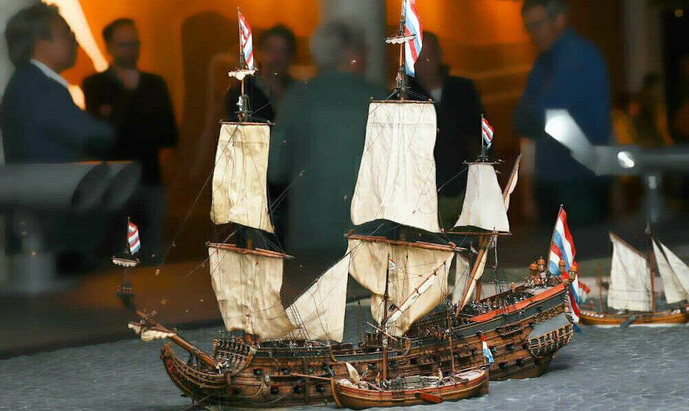
See you are familiar with the work of the Thomesen brothers. They build a complete fleet of resin vessels to display the Dutch fleet in the 17th century at anchor before the island of Texel.
It is a pitty they don't sell these ships as a kit whereas they sell a lot of other models as kit.
See below de reede van Texel.
View attachment 132210
View attachment 132211
View attachment 132212View attachment 132213
View attachment 132214
View attachment 132215
Just found your build log, incredible work and probably a reason I have no plans to tackle this ship as I could never do it justice.
 , I’ve been puzzling over my initial drawing, in relation to the Berain drawings, for about an hour and I think I see a path toward what Nigel is suggesting. I’m going to do a bit more drawing - on vellum, this time, and we’ll see where we end up. Thank you, Nigel, for speaking up. These arches are an important element of the stern, so it is pretty high on the priority list to nail it!
I meant to mention, Nigel, that I have not thought to wash the acetate; this makes perfect sense, as it is always covered in static-electric-inducing film. Always learning as I go.
Hello, Richie - Welcome to my log! I am glad you have found this project. This interpretation of Soleil Royal resides in Brooklyn, New York. Thank you for the kind words - ‘much appreciated!
Last edited:
- Joined
- Aug 30, 2020
- Messages
- 684
- Points
- 353
I shall observe with interest.
I meant to mention, Nigel, that I have not thought to wash the acetate; this makes perfect sense, as it is always covered in static-electric-inducing film. Always learning as I go.
Hello, Richie - Welcome to my log! I am glad you have found this project. This interpretation of Soleil Royal resides in Brooklyn, New York. Thank you for the kind words - ‘much appreciated!
Is New York where the Thomesen brothers fleet of Dutch fleet in the 17th century resin vessels are located, is it something anyone can visit.

Hi Richie,I shall observe with interest.
Is New York where the Thomesen brothers fleet of Dutch fleet in the 17th century resin vessels are located, is it something anyone can visit.
This is actually in a small museum at the island of Texel Netherlands.
Expositions
The diversity of Museum Kaap Skil is clearly visible in the exhibitions. In 'World Voyage', you follow the ships in the 16th, 17th and 18th century to their destination all around the world. Be amazed by the great value of the cargo in the Palmwood Wreck exhibition and dream away whilst viewing...
 www.kaapskil.nl
You can find something about the build here.
VOC – Artitec
- Joined
- Aug 30, 2020
- Messages
- 684
- Points
- 353
Excellent thank you Maarteen, that was quite fascinating looking through those links as I had no idea of it's existence.Hi Richie,
This is actually in a small museum at the island of Texel Netherlands.
Expositions
The diversity of Museum Kaap Skil is clearly visible in the exhibitions. In 'World Voyage', you follow the ships in the 16th, 17th and 18th century to their destination all around the world. Be amazed by the great value of the cargo in the Palmwood Wreck exhibition and dream away whilst viewing...
You can find something about the build here.
Will put it on my must see list if I ever get back that part of the world.
Last edited:
I see, now, that I was mis-reading your question Richie - hand to face; my apologies! Thank you Maarten for clarifying. If you do get a chance to see the Texel diorama, Richie, it is absolutely worth the trip.I shall observe with interest.
Is New York where the Thomesen brothers fleet of Dutch fleet in the 17th century resin vessels are located, is it something anyone can visit.
I may not be fully understanding you, though; I wonder if what is triggering your observation is the way that the balcony pilaster, in-line with the pass-through archway, has a definite inclination toward the hull. Is that what you mean by truncated?
Marc when I say truncated, I mean the out profile of the quarter galleries start to taper inward to follow the tumblehome but then your template has them jutting outward again.
Regarding matching the arch to those over the windows, visually I think you can get way with these arches being slightly narrower over the open gallery as visually the panel below in the balustrade appears narrower although dimensionally it may not be.It is less above measurement and more about what the eye sees and one's perception of it, if you know what I mean.
Kind Regards
Nigel
So, I’ve re-drawn the bracket. The roof is the same, but the angle of the pillar has changed, as well as it’s heft, and the acanthus carving and scrolls are improved. Is this more what you were thinking Nigel?


And Before:

And Before: