
Hello,
It is a master's job.
It is a master's job.

 |
The beloved Ships in Scale Magazine is back and charting a new course for 2026! Discover new skills, new techniques, and new inspirations in every issue. NOTE THAT OUR NEXT ISSUE WILL BE July/August 2026 |
|
 |
As a way to introduce our brass coins to the community, we will raffle off a free coin during the month of August. Follow link ABOVE for instructions for entering. |
|
Hi Marc,We’re literally coming down the home-stretch with Dad. We moved his furniture and belongings, this past weekend, and we will move him this coming weekend - HUZZAH!
Naturally, work on the ship is fairly meager, but I did get the deck sheathing and stove painted, and I did manage to make-up and fit the forecastle beam that will be visible at the break of the forecastle deck. A montage that shows my paint processes, particularly for my natural “oak” finish:
View attachment 275683
For some reason, I can’t load the other two pics of the sheathing because of an “unknown server error”. Anyway, the process is pretty straightforward; flat black spray primer, followed by Citadel silver (allowing some black to peak through), finished with grey enamel wash. The enamel wash picks up all the nail heads and sheet seams nicely, while giving an oxidized metal finish. The white stripes are masks for where the stove glues down.
The stove begins with Modelmaster Random Tan as my base coat over white enamel primer:
View attachment 275684
Although it will never be seen, I chose to represent the brick work that is sandwiched between iron and wood.
Next, I slather the whole thing in Windsor and Newton medium grey oil, and allow it to sit for five minutes, or so, before wiping most of it away. This paint gives the wood a pleasing silver-ish cast, like newly oxidizing oak, and it gets into all the plank seams and grain structure:
View attachment 275686
View attachment 275685
Next, after allowing it to cure for a few days, I do the same thing again with W&N Van Dyke Brown. This is what restores a sense of woody warmth to the surface, while enhancing texture and depth:
View attachment 275687
The plate mounted to the deck:
View attachment 275688
The iron blacked-in:
View attachment 275689
I decided to rub some powdered graphite over the black, so that the lattice would pop a little. Again, this will never be seen, but I wanted to play around with powder effects. It is subtle, but effective:
View attachment 275690
View attachment 275691
Lastly, the stove on-board:
View attachment 275692
View attachment 275693
The stove gives me a central glue connection for that beam, which will lend some rigidity to the whole deck structure.
In other news, I have 2 of 3, aft bulwark gussets fitted and installed. All the prep work on the last bulwark is done, so I will resume painting soon.
I hope all are well, as the holiday approaches. Thank you all for stopping by. More to follow!


")


 .
.Hi Marc,I’ve done a fair amount of hemming and hawing over a number of things, but I eventually arrived at the place(s) I think I need to be.
For clarification of the earlier discussion; this is the essential problem of my stern winding out of square. Note, how the starboard aft edge of the upper bulwark increasingly extends beyond port:
View attachment 294739
I thought I might try drawing arcs of round-up that ranged from extreme to conservative:
View attachment 294737
View attachment 294738
View attachment 294736
I started with the extreme line (far right), but ultimately - a more slight increase of round-up (middle line), appeared to me to be the most organic possibility.
Here is what my ultimate choice of round-up looks like from the starboard side:
View attachment 294734
It is just enough, I think, to help balance this incongruity - if not completely.
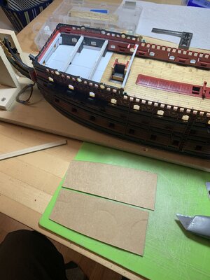
It seems to me that I can also help balance this out when I make the upper stern balcony. Here, I have pulled a uniform cardboard template just away from the port side, so that the outboard edges of the stern balconies align:
View attachment 294735
I think this will help align visual perception at the exact point where it is most important.
At the end of the day, I am pleased with the slightly increased camber of this bridge-piece:
View attachment 294733
One thing that has become interesting to consider is this: in gluing up the aft bulwarks, I was very conscious of establishing a realistic sense of tumblehome, as the bulwarks rise. Even accounting for my initial increase in breadth, in the early drawing, I inadvertently maintained the slab-sided verticality of the kit stern. In the left margin, I have noted the discrepancy between where I have arrived, dimensionally, versus where I began schematically:
View attachment 294724
Pictorially, here is the discrepancy for real:
View attachment 294725
What is completely fascinating is that the upper width of the stern is almost identical to the stock dimension. Here is the stock poop deck, in place:
View attachment 294727
Even though this is not where I thought this project was going, when I started, the improved sense of tumblehome was well-worth the sacrifice in stern-width. This isn’t perfect, but it looks more right than wrong:
View attachment 294723
View attachment 294731
View attachment 294732
A montage of development for the next tier of stern lights:
View attachment 294728
View attachment 294729
The pilasters of the lower balcony rail don’t seem to align, but this is not reflective of reality. Again, it isn’t perfect, but it’s pretty close.
After drafting:
View attachment 294722
View attachment 294721
This isn’t perfect. The drawing can be improved upon with the carving tools, themselves. For the most part, I think this works. I wonder whether I should follow the Berain drawing a little more closely and include an extra line of horizontal window mullions. The false side lights, at this level, have five horizontal lines, but I am trying to balance this tier with the actual stern lights below.
Just for fun, a different iphone filter - Le Soleil Noir:
View attachment 294720
View attachment 294730
As always - thank you for looking in. Bon noir!


")

