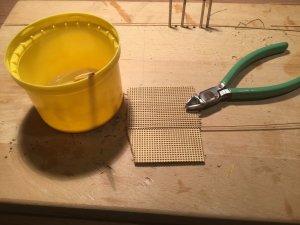
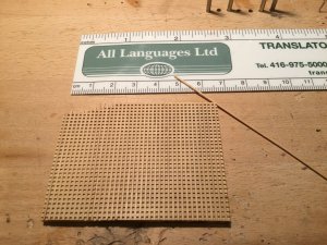
Very delicate woodwork.
-

Win a Free Custom Engraved Brass Coin!!!
As a way to introduce our brass coins to the community, we will raffle off a free coin during the month of August. Follow link ABOVE for instructions for entering.
-

PRE-ORDER SHIPS IN SCALE TODAY!
The beloved Ships in Scale Magazine is back and charting a new course for 2026!
Discover new skills, new techniques, and new inspirations in every issue.
NOTE THAT OUR FIRST ISSUE WILL BE JAN/FEB 2026
You are using an out of date browser. It may not display this or other websites correctly.
You should upgrade or use an alternative browser.
You should upgrade or use an alternative browser.
Sovereign of The Seas 1637 - Heavily modified Mantua kit
- Thread starter modelshipwright
- Start date
- Watchers 35
Excellent work Bill and great to see you back at the build.The great thing about this vessel is so much is down to the interpretation of the modelbuilder.To my knowledge,yourself,Janos,Hubert from Germany(sorry his surname escapes me) and myself are all working from Busmann's book and other contemporary sources and still have differences because despite all the research there are still many grey areas.I think that is what makes this vessel so interesting to build in model form.None of us could be proved wrong,you would need a time machine to do that.There would be some interesting arguments if any of us entered our build in a competition,something along the lines of Naviga .
.
I have sent you an email,hope it finds you ok
Regards
Nigel
 .
.I have sent you an email,hope it finds you ok
Regards
Nigel
Excellent work Bill and great to see you back at the build.The great thing about this vessel is so much is down to the interpretation of the modelbuilder.To my knowledge,yourself,Janos,Hubert from Germany(sorry his surname escapes me) and myself are all working from Busmann's book and other contemporary sources and still have differences because despite all the research there are still many grey areas.I think that is what makes this vessel so interesting to build in model form.None of us could be proved wrong,you would need a time machine to do that.There would be some interesting arguments if any of us entered our build in a competition,something along the lines of Naviga.
I have sent you an email,hope it finds you ok
Regards
Nigel
Thanks Nigel. Yes, it is somewhat of a mystery in a lot of areas so we have to be creative in our interpretaion of the Sovereign. Keeping in mind that the Payne engraving, the Ven de Velde sketch and other representations from the period were done by individuals viewing the ship, it is easy to see why they vary. These artists were the reporters of the day and we have only their work to look at in order to see what the ship looked like. Yes, a time machine would be very helpful at times as some areas of the ship remain unseen in the works described. Research into other ships of that period are helpful like the Vasa in order to get an idea of what some aspects might have been like. If we all brought our models into the same room, I am sure they would differ in many respects.
Regards,
Bill
Hi Bill, Is there a way you can show close-up photos for sliding table jig? If it not difficult to build I would at least try...as I have typical trouble with alignment.
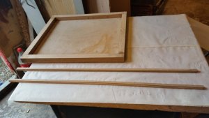
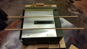
Here is a series of pictures of the fixtures used. The first photo is of the sliding table fixture sitting on the Byrnes saw.
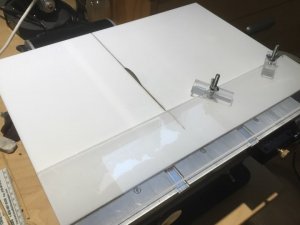
The next photo is of the underside of the same fixture. It shows the strip of acrylic glued to the underside of the table. This strip is the same width as the table saw slot and guides the sliding fixture back and forth. You can also see the countersunk screws that are used for the two clamps shown in the first photo. Additionally there is a piece of acrylic glued to the underside that acts as a stop when sliding the table forward. If you slide too far you will cut the fxture completely in half. It stops on a screw that is mounted in the edge of the table saw table at the back right corner.
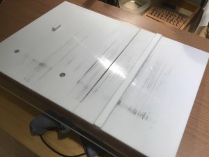
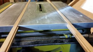
The next photo is of a secondary jig that is used to cut the slots in the wood. It has a piece of boxwood glued to it at the same distance from the blade as the blade thickness, in my case 0.032”. It guides the block when taking cuts.
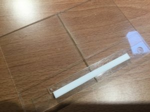
The strips of acrylic glued on top of each other at the bottom of the photo are strengthening strips to prevent the fixture from being sawn in half.
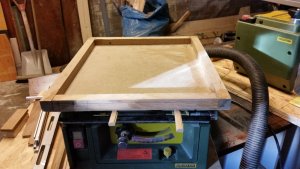
The last photo shows the small fixture clamped to the sliding table fixture ready to cut slots. You adjist the blade height to be the same as the slot width so that later, strips of 0.032” boxwood can be laid into the slots to create the grate.
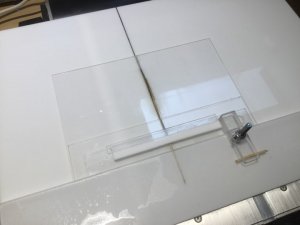
I hope that shows it clearly as acrylic does not photograph well because of shine from the lights. If you have any questions, please ask.
Regards,
Bill
Last edited:
Great job, Bill, as always. I lack (and envy) the consistency of your build. I also made the gratings on my SoS on the circular saw, but with the conventional method - creating the comb-like pieces and then assembling them into each other. I just have to find the blade of tge proper thickness for it.
Janos
Thanks Janos.
Regards,
Bill
Bill I'm about to make a sliding table,
but after seeing your table I will make it again in acrylic such as your sliding table.
Thanks for showing, a couple of pictures of my project.
View attachment 80969View attachment 80970View attachment 80971View attachment 80972
I see that you are using two rails to guide your fixture. The reason mine has only one rail is to account for expansion and contraction of the acrylic so it slides easily in all seasons and humidity levels. With two rails it will bind at some time of the year. Therefore you always push the left hand side of my sliding fixture when using it. Good luck with your fixture.
Regarda,
Bill
Last edited:
Just a footnote to the acrylic jig. The adhesive we used to glue the parts together is Methylene Chloride (Resin Bond) adhesive. It was applied with a syringe and bonds almost instantly with no residue at the joins. It evaporates very fast. It should be used in a well ventilated area.
Regards,
Bill
Regards,
Bill
Thanks for the pictures and detailed explanation Bill. Now I understand.I hope that shows it clearly as acrylic does not photograph well because of shine from the lights. If you have any questions, please ask.
Bill, fine work with deck grating,do you use the sliding table to make it ?, it would have been exciting to see how it is done, thank you.
Thanks Knut, I appreciate your comments. If you scroll up the page from this post, you will see a series of photos of the sliding table. The third photo shows a secondary jig which is mounted to the sliding table for cutting the slots in the deck grate. It includes a strip of 0.032” boxwood glued to the surface at a distance of 0.032” from the saw blade. It is the guide for positioning the block when making successive cuts in order to space them the correct distance apart. You simply index the block of wood to the right aligning the previous slot in the boxwood strip to obtain the 0.032” distance between slots. After cutting all the slots in one direction, you turn the wood 90 degrees and cut the slots perpindicular to the first set. I hope that explains it.
Regards,
Bill
Great work Bill.I have one question.I notice you have what looks like an assembly jig.I assume it is dilute PVA in the yellow container.Does this not stick the grating to the jig as well as stick the grating together?Or do you remove the grating from the jig prior to gluing?
Kind Regards
Nigel
Kind Regards
Nigel
Great work Bill.I have one question.I notice you have what looks like an assembly jig.I assume it is dilute PVA in the yellow container.Does this not stick the grating to the jig as well as stick the grating together?Or do you remove the grating from the jig prior to gluing?
Kind Regards
Nigel
Hi Nigel.
The yellow cap is off an aerosol spray can and contains water diluted yellow wood glue used to glue the 0.032” strips into the grating. The grating is sitting loosely on top of a wooden kitchen carving board. there is no fixture used at this point. Hope that answers your question.
Regards,
Bill
Bill,yes it does,the penny has dropped,The ledges are all in one piece with battens glued in.I originally thought both were individual pieces and you had cut grooves in boxwood sheet to aid assembly.I have done it your way with pearwood but using my Proxxon Mill.I then reduced the thickness removing the 'backing' on the disc sander when the glue had thoroughly set.This also opens the holes up so you can see through it.
Kind Regards
Nigel
Kind Regards
Nigel
Bill,yes it does,the penny has dropped,The ledges are all in one piece with battens glued in.I originally thought both were individual pieces and you had cut grooves in boxwood sheet to aid assembly.I have done it your way with pearwood but using my Proxxon Mill.I then reduced the thickness removing the 'backing' on the disc sander when the glue had thoroughly set.This also opens the holes up so you can see through it.
Kind Regards
Nigel
Yes, that is correct. I sand down the top surface after gluing in the battens. As they are only 0.032” deep, it would be risky to sand the back side down to allow the holes to go right through. At a normal viewing distance the holes appear natural.
Regards,
Bill


