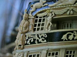
Stern Decorations - Hahn Drawings - Prototypes

WHAT AND HOW IS A STL FILE
Hello Don!! An STL file is nothing more than a type of 3D file used by 3D printers and people who create 3D artwork. STL is short for STEREOLITHOGRAPHY. The letters themselves would be the filename extension such as filename.stl just like you would see a text file named filename.pdf or filename.txt. STL files are made from thousands of tiny geometric triangles and such to create the final form of the object. While they would seem foreign by a human, they can easily be read by a computer. STL files are not the only type of 3D files but they have become more common as a result of the invention of 3D printers.

DO YOU NEED THIS IF SOMEONE PLACED AN ORDER FOR LET US SAY SIMPLY CANNONS IN A CERTAIN SCALE
We would not need an STL file for cannons if I already have the cannons you are looking for in my inventory of 3D objects. As you know there are many different types, shapes, and styles of cannon. There are also various crests and emblems that go on cannon. So, if I already had the cannon you needed then all I need is wood and we can directly fabricated it. If it is an all new cannon design, I either have to draw it from scratch or someone would have to provide a drawing or an STL file of that specific cannon. Make sense? The scale really does not matter because I can take any object in the computer and render it to whatever size we need.

WHAT WOULD HAPPEN IF SOMEONE WANTED SOMETHING FROM A SET OF PLANS
If those plans are in a computer format such as a PDF file, they can be emailed to me and I can work from there to create proper CAD drawings for fabrication. This is the part that takes hours and hours of work. Drawings such as from Jeff Staudt are nearly perfect and take very little additional work. Drawings that are from original hand drafting or sketches such as historical work can be a nightmare for someone like me... that is where a person like Dave Stevens or someone who has more expertise in drafting and CAD comes into play.

If those plans are not in a computer format and only exist on paper, then the work is even more daunting. In this case we either need to scan the paper copies into a computer and redraw (lots of errors here), trace over the paper plans using a digital drawing tablet, or completely redraw the plans in the CAD software from scratch. All of these methods is a tremendous amount of work. MORE than building the actual model itself!! For a complete ship it would be hundreds if not thousands of manhours. This is why it takes more than one person.

You asked very good questions and I hope this helps everyone understand better what it takes to design a model.
 
The question is not a simple extrusion, this is basic stuff. The question is how do you create an extrusion between two free surfaces - one being the irregular, 'free' shape of the hull to which the gallery should fit and the other again irregular shape (which though can be probably described by a number of 'regular' shapes like cylinders and cones) which describes the outside of the gallery.
János


this falls into organic modeling where odd shapes are formed here are a couple video demos that show this process. This is using Sketchup but the process is the same in all software.


organic modeling
Very, very cool Dave. I have never used Sketch-Up and definitely see it has some nice tools. Especially, like the sandbox artist tools shown in the second video. Regarding the first video where he is showing how to make a motorcycle gas tank from 2D drawings I find the most interesting. I can accomplish those same things inside Vectric Aspire using the sweep between vectors, extrude along vectors, and shape by spinning or turning a vector - with far fewer mouse clicks. Different software, different technique.... same results. I love it!!!
 
whats your thought on this?

This CNC machine must be assembled. It is primarily made as an "educational tool for learning". It is not designed for model ship building. It cannot accomodate the type of bits needed to carve hardwoods and the cutting area is very small. The vertical z-axis travel is only 45mm (1.77"). The electric motor looks like something out of an R/C car. The high-speed spindle on my machine produces 1.15HP. Huge difference.

What is my thought? Good for learning. Not good for model building.
 
Good for learning. Not good for model building.

Yes that was what I was thinking. I have no experience at all with cad or cnc, the most complicated I know is using a wood lathe.
I didn't think for a moment it would come anywhere near close to what you can make, but as something cheap to learn with and
just goof off I thought it might prove fun and educational. My other thought was my middle son is taking cad classes at the collage
near by, he may get a charge out of it. But, this is why I ask the experts. Thank you :)
 
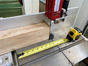
I apologize for my delay in continuing our discussion on this thread. But, I need to pause while I slice up some Boxwood for more prototyping. While I am very adept at model sized tools, I will fully admit at being frightened of fulled sized saws. My Admiral has her own 1:1 scale wood shop. I need to borrow her 240V, 2HP, Grizzly bandsaw with a 17" throat. This thing is floor standing, has a pretty big fence, and freaks me out. Probably nothing at all for Dave Stevens. But I need to get this slab of Boxwood down to hobby size so we can do some more CNC work.

First I gotta set this thing up and check EVERYTHING over. Not saying I don't trust the Admiral with her tool calibration... but.. ummmm. Safety Tip: When using someone else's power tools, always, and I mean always check all tooling, settings, adjustments, and calibrations. Well heck... the 240V plug does not match her 240V receptacle... how does she use this thing? Must be an adapter around here somewhere. This might take a while folks....

IMG_0345.jpg

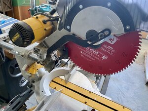
Multiple members of this forum were trying to talk me into using the Admiral's 12" compound sliding chop saw!! I will not call them out but they know who they are.. LOLOLOLOL.. Luckily, sanity prevailed and another member of this forum (thank you @DonRobinson ) talked me out of it for fear of bodily injury. If you look closely, you can see the gouge in the kerf slot of the saw caused by the Diablo blade. I call this Admiralty Calibration Method.

Hopefully, some of you may have picked up a few tips today. Even though we didn't actually get to fabricate anything.

Sail on.

IMG_0343.jpg
 
I learn more from you and other members posts in 1 day than I ever did before. Really, I mean it and Im not being my usual jokester self here, YOU GUYS ROCK here.
Thank you Mr. Shanks & Mrs. Shanks, your attentive class clown is actually paying close attention. Now, if you'll excuse me I got called to the principals office...
Something about spit balling members of that "other" forum :P
 
I learn more from you and other members posts in 1 day
I learned something too. The Admiral doesnt know where her NEMA 14-50P to 6-20R adapter is and doesn't have time for my nonsense. Luckily for me, my mistress Amazon has one and it will get here Thursday. Sorry @zoly99sask , I will just have to find something else to do until then. Maybe render up some 3D curtains for the back of the Alfred... hmmm.
 
Well heck, here is a first stab at the preview rendering. It still needs folds, wrinkles, weight and more details. But it is perfectly to scale. There will be a 1/16" flat base on the bottom the modeler will carefully sand down for a custom fit and allow the wood to slightly bend. Once I finish the shaping in the computer, we will still need to toolpath it, run simulations and then be ready to prototype it on the CNC machine. This is for the HMS Alfred stern. It goes in the area above the upper row of windows below the statues. All I did was trace the CAD drawings for the Hahn plans, and then use the create 3D object in Aspire. Enjoy.

Alfred Curtain.jpg
 
Last edited:
I am hoping to finish adding details to these HMS Alfred curtains today and CNC a prototype. It really isn't that much work. But today I am doing research of a much more important matter!!!

View attachment 164996


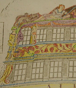
those drapes come down over the end windows like the image below. Those ends were missing on my original CAD drawing. I will go back and add them.

boop.JPG
 
now that the lumberyard site has the Ships of Scale banner on it more builders of Hahn models are coming here looking for stern windows and carvings.

i am also getting more and more requests for larger scale stern kits.

my drawings are CAD drawings like this drawing of the Confederacy, this has to be refined and Mike can work his magic on the files to create 3D carvings. some builders don't mind resin cast carvings and others would like to replace the resin castings with CNC milled wood carvings sets to replace those in kits.

confed.JPG
 
i found this image in the Hahn library see where Harold ended the drapes, now go back and look at post #117 the original drawing. They are not the same.

Harold did say his models were uniquely his and that is what got him in many heated debates with the purest crowd. Models should be as close to historically accurate as possible and not just made up willy nilly.

Both sides make a good point the historically accurate and the made up models. How accurate? well the drawing shows the drapes one way and Harold did it his way. so

SCN5088.jpg
 
Back
Top