Stern Decorations - Hahn Drawings - Prototypes

How accurate? well the drawing shows the drapes one way and Harold did it his way. so
Great question. My answer comes with a perspective....
  • If the builder is limited to a kit, they must build what came in the kit however accurate it may or may not be
  • If the builder can purchase after market parts, they are limited with those parts they can purchase however accurate they may or may not be
  • If the builder can scratch build the parts, they get to decide how accurate they want their model to be - only limited by their own research and skill
  • If the builder collaborates with a custom fabricator, they get to decide how accurate they want their model to be - only limited by their own research and the limits of the fabricator
In the end - it is the builder's choice. If the builder is commissioned by a museum, for pay, then they will probably make every effort to build the model as accurate as they possibly can. If the builder is building the model for themselves, they will no doubt build as they choose.

After all... it is a hobby. You should never allow any person to dictate what you can or cannot build. That choice will always be yours.
 
Harold stood his ground on his models and how he built them. in the end he was run out of town by the purest but who got the last laugh?

Hahn models sold for $30,000.00 even reproduction built from his plans sell for $12,000.00

who do you think got the last laugh?
 
Regarding fidelity to the plans, I think we need to keep several things in mind. In situations where the original draughts are the only record of what was to be build, we have no idea how accurately the finished product reflected those plans (assuming the ship no longer exists). Even in cases where there are contemporary paintings or illustrations of a particular ship, they often vary, one from the other, and from the draughts.
 
that is very true Dave each and every ship built was a one off one of a kind so we really don't know exactly how the final ship was built.

i suppose there is the nitty gritty of nit picking every last detail and the over all design of the ship. Over all Harold represented the ship, finer detail well iffy maybe.

there is accuracy in research, in designing and drafting and in fabrication. Maybe there are thing Mike can not do so the next best thing will have to do.
 
Dave,
close up scrutiny of Alfred plans reveal considerable artistic licence of Mr Hahn.
For example the lion figurine on the top left side of the stern galley is not a lion at all. I see it as a seahorse. What you you think ?
 
Let's continue today with the stern windows of our Alfred and explore a couple more aspects of CAD and laser technology. Yesterday, we cut out a row of stern window openings and 3D columns in 1/8" cherry. Then we glued them up to create a 3D assembly. Now it is time to add some window frames inside the window openings themselves.

The upper drawing shows Dave's original draft CAD drawings for the stern windows. If you recall, he had previously mentioned the problem of using high powered industrial lasers causing smaller parts to burn and crumble. Because of that, he increases the kerf size of the window frames in an attempt to compensate for this problem. Those of you who use saws already understand that kerf is basically the width of the cut left over by the blade passing through the material. A laser also has a kerf although much smaller than any saw. We know from looking at Hahn's drawings of Alfred, the window frames should be much thinner than in Dave's original draft drawing. He knew this but had to make up for the larger kerf of an industrial laser.

In the lower drawing, I have modified the frames to match the actual dimensions of Hahn's model to much more closely depict how the actual window frames looked. Since the frame shapes are trapezoidal, I used the transform - skew functions in CAD to adjust them. My goal was to get 0.05" spacing around all the window frame elements while keeping the overall symmetry as perfect as possible. Since the kerf on the Epilog laser is so very small we should not have a problem cutting this out.

View attachment 163974

We cut both sets of parts out on 1/16" yellow wood. This operation took 2 min 13 seconds. I used a different color wood in order to provide some contrast against the cherry although it will not show up that well in the upcoming photos.

View attachment 163978


As you can see there is a significant difference in the size of the window frames with the modified version looking much closer to scale.

View attachment 163979


Next, this is where the prototype builder would get involved. The window frame parts are punched out (no tabs) and glued into the window openings from the back-side. The CAD design include a tiny step allowing for a single drop of CA in each corner to hold the window frame in. You will notice the window frame is recessed into the 1/8" cherry billet (by design) and leaves room for a clear acrylic window behind the frame. Yes, the Epilog can cut out clear acrylic windows.

View attachment 163980

Once all the frames have been glued in we are left with a pretty nice looking result. Remember, this is only a prototype. We would want to refine this much further before it would be worthy of going on an actual model.

View attachment 163983

The overall effect of 3D Assembly begins to take shape.

View attachment 163988

As you can see, the window frames are approaching 1/32" wide. This is using my standard focus lens. I have a high definition lens that allows a focus of 1/3 the kerf size of this one. Also note, the laser char on the inside of the window frames actually creates additional depth and I believe is pleasing to the eye from an artistic viewpoint.

View attachment 163989

Questions, comments are always appreciated.

Sail on!!
it's Vary nice
 
I just noticed you did the stern decorations for the Confederacy. I have an on again, off again scratch build of the Confederacy going and need a set of decorations in 1/48 scale. Is this something you can do?
 
Hello everyone. So let us jump over to the world of CNC carving. Computer Numerical Control (CNC) is a computer controlled machine tool that basically runs on and x/y (left/right) gantry and also has a certain amount of z-axis (up/down) travel. Educational/hobby style CNC tools might be purchased or assembled for several hundred dollars or you could see CNC machines in automotive, aerospace, or Formula 1 industries in the millions of dollars. Many people refer to them as CNC Routers because common woodworking or furniture making CNC machines use a router mounted in the gantry to spin the bits. For precise miniature model work we need higher end equipment. My CNC machine is made by ShopBot Tools right here in North Carolina USA and features a Bosch High Speed Spindle. For you woodworking fanatics my dust collection is provided by Festool. Gotta love German engineering. Ok, enough of the hardware... What are we gonna "make" today?

As we can see in the Hahn picture below, our 1:64 Alfred prototype needs some lettering on the stern. I haven't found those on Dave's massive CAD drawings yet so let's see if we can make our own and then carve them in 3D on the CNC machine. First, we had to search through our huge font library and find one that matches the Alfred lettering that was hand carved by Hahn. The match I found was Bodini Book Normal. I typed out the word ALFRED in my CAD software and then scaled it to fit the area below the stern windows we had already created. I found this font size to be 46.856pt for 1:64 scale. Ok, easy enough.

Next, I used Vectric Aspire's Create 3D Shape function - Flat and added about 9degrees of curve to the top. I set the overall thickness of the letters to be 0.125" and added .0625" to the base for a total of about 3/16" tall. I inserted the letters into a 1/2" virtual slab of wood and moved over to the tool path simulator to select bits and run simulations over and over and over until I got the results we needed. All of this work took several hours. But once done... it is done forever!! I sent the CAD over to my post-processor to create CNC code and warmed up the high-speed spindle for 10 minutes.

Some of us cannot carve like Harold Hahn so we need help!!

View attachment 164149

This project will consist of 2 jobs. First we will use a 1/8" Carbide Ballnose (upper bit) to rough out all the excess wood from the billet. Then we will change over to a 1/16" Tapered Ballnose for finishing and cutout. We will use an Onsrud 1/4" hardened steel shank holder to secure the bits in the spindle. Each of these bits go for nearly $100 a piece.

View attachment 164150

When CNC carving small, highly detailed parts we want to use the hardest, tightest grained wood we can. Boxwood and Pear are two of the best. For this prototype I have selected a 1/2" slab of hard maple. Clamp it down to the spoil board with some good Rockler clamps. We could also use screws.

View attachment 164161

Although the billet is labeled as 1/2", for precise CNC machining we must ALWAYS measure it. This billet is actual 0.518" thick. We install the first bit and then zero the z-axis against the touch plate on the spoil board. Since we will be carving all the way through the wood, we set our z-axis zero to the surface of the spoil board and not the surface of the billet. When the steel bit makes contact with the plate a small electrical circuit is made and the computer zero's out. The thickness of the plate is already factored in.

View attachment 164166

We fire up the job and we are off. The 1/8" ballnose bit will spin at 14,000 rpm while the CNC machine executes 7825 lines of code. We can monitor the job progress on the laptop sitting next to the machine.

View attachment 164167

The roughing job took 20 minutes to complete. This could have been greatly reduced had I used a 1/4" billet instead of 1/2". You see the result of the roughing job below. It looks horrible!!! What went wrong?????

View attachment 164168

Nothing went wrong. Time to install the 1/16" Tapered Ballnose, spin that sucker at 18,000 rpm, executing over 25,000 lines of code for 26 minutes. This is where the magic happens.

View attachment 164169

What emerges is this mess!! Ah, but looks can be deceiving.

View attachment 164171

The letters are removed from the billet attached to a paper thin wafer of hard maple.

View attachment 164173

This is where our prototype builders would get involved. The maple backing is so thin we simply cut the letter out with scissors.

View attachment 164175


Spend a few minutes cleaning them up. I really did not put much effort in here. After all, these are only prototypes.

View attachment 164176

Finally, we mock them up against the stern windows we already made. Looks pretty good for a first prototype. The letters are actually thicker than they would be on the final model. This is on purpose. The modeler would thin them down from the backside using their Byrnes Disk Sander to a final thickness of about 1/16" and then carefully glue them to the black planking wales on the stern.

View attachment 164177

Another view to see the carved 3D shape. The end result is just a hair over 1/8" thick at 0.14". These are in hard maple. We could easily get a lot more definition out of boxwood or pear. A few more prototypes and simulation runs and we could bang them out by the hundreds. As you can see, CNC is both much more complicated and a lot slower than using a laser. But the results that can be obtained are nearly limitless. I skipped over a lot of details, otherwise this would have been a book. But there you go.... questions, comments, feedback always welcome!!

View attachment 164178
Hi Mike,
What wonderful talent and execution. I get excited when I see two desperate worlds come together, like art and engineering. Really a wonderful form of architecture. Superb work!
I have a challenge I've been putting off Mike. My Santisima Trinidad (OcCre) 1/90 project has stalled a bit with my work on its stern plate decorations I've attempted to hand carve the scroll decorations but I'm not happy with the results. I'm wondering if you can help me produce a better quality product, for which I'd be more than happy to pay for.

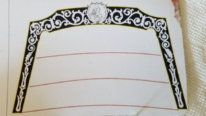
This is the scroll pattern I settled on and wanted to carve it myself. I think I had a slightly inflated opinion of my own talents, this being my first model project and first carving attempt, hahahah. I've learned a few things about myself during this project.

20200718_115820.jpg

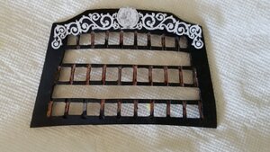
This is the pattern loosely fitted on the stern plate and to me this is the look I'm going for. It is missing the vertical scroll pattern legs.

20200718_115845.jpg
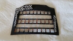
Last and least, my attempt to carve from boxwood, with a white wash. The scroll work in boxwood was very fragile, due to the scale. I did have it glued to a substrate to add structural strength, but alas it did not stand up to my heavy hand.
20200718_115802.jpg

Is the fabrication of this scroll pattern something you could/would do via CNC method? If you would be willing to do this crazy work, what would you need from me. As I stated I would be happy to pay the going rate for such high quality work you do.

Thanks in advance Mike!

Stay safe!
Ken
 
I would be happy to pay the going rate for such high quality work you do.
Hi Ken.... the decorations you need would be much better suited for 3D printing!!! I am sure Kris can help you with this....

3D PRINT I'm sure in 100% there is no problem.
So very true.... when we get down to very fine levels of detail this is where the advantage of 3D printing takes over from CNC...
 
Hi Ken.... the decorations you need would be much better suited for 3D printing!!! I am sure Kris can help you with this....


So very true.... when we get down to very fine levels of detail this is where the advantage of 3D printing takes over from CNC...

Thanks for the fast response guys! Can someone direct me to Kris? Or....is there a section in the forums where members post their talents and services? I apologize for my ignorance in this area.

Somewhere I once heard that saying, "You don't know what you don't know." I never really understood what that meant but I'm pretty confident "I do know what I don't know." and in this case need someone who does know....hahah. How's that for a convoluted bunch of thoughts! ROTF
Anyway, thanks for the help fellas!

Stay safe!
Ken
 
HI KEN, EVERYONE IS RIGHT THIS IS SUITED FOR KRIS, I ORDERED SOME DECORATIONS FROM KRIS FOR MY ARMED LONG BOAT AND HAVE RECEIVED THEM GREAT WORK EXCELLENT DONE WITH 3-D, YOU CAN CHECK THEM OUT WHERE I SHOW THEM, ON THE THREAD PURCHASED SHORTLY AGO, HOPE THIS HELPS, AND THERE IS QUITE A BIT POSTED BY KRIS, JUST DO NOT REMEMBER WHERE, HOPE THIS HELPS. GOD BLESS STAY SAFE DON
 
Back
Top