Swan Class – ¼” Scale - Stuglo [COMPLETED BUILD]

Hi Stuglo, your deck planking looks great. I think Uwe can definitely enlighten us about the background of this type of planking.
I will try, but can also only summarize what I can find in moment

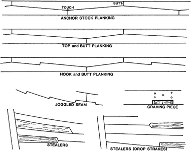
  • Anchor stock planking (Fig. G-11a). A form of planking in which the longitudinal shapes of the planks resembled anchor stocks. It was similar to the top and butt method of planking and was intended to prevent shifting and increase the longitudinal strength of wales and other stress-bearing planks.
  • Top and butt (Fig. G-11a). A method of planking whereby one edge of the planks were straight while their opposite sides had two sloping edges of unequal length, reducing the plank widths to half. It was used to increase longitudinal strength and to prevent shifting of wales and other stress-bearing planks.
  • Hook and butt (Fig. G-11a). A method of planking whereby one edge of the plank was straight while its opposite side had sloping edges locked by a hook. Infrequently, the term was also used to denote a hook scarf. (p. 1125) (p. 1126)

oxfordhb-9780199336005-graphic213a-full.gif


Usually the margin plank has a hook and butt joint as a connection

also an interesting read

 
I will try, but can also only summarize what I can find in moment

  • Anchor stock planking (Fig. G-11a). A form of planking in which the longitudinal shapes of the planks resembled anchor stocks. It was similar to the top and butt method of planking and was intended to prevent shifting and increase the longitudinal strength of wales and other stress-bearing planks.
  • Top and butt (Fig. G-11a). A method of planking whereby one edge of the planks were straight while their opposite sides had two sloping edges of unequal length, reducing the plank widths to half. It was used to increase longitudinal strength and to prevent shifting of wales and other stress-bearing planks.
  • Hook and butt (Fig. G-11a). A method of planking whereby one edge of the plank was straight while its opposite side had sloping edges locked by a hook. Infrequently, the term was also used to denote a hook scarf. (p. 1125) (p. 1126)

View attachment 296244


Usually the margin plank has a hook and butt joint as a connection

also an interesting read

Hello Uwek, he is not recalled for the deck of the decks, my observation is for the bridge, Thanks for your availability
 
I will try, but can also only summarize what I can find in moment

  • Anchor stock planking (Fig. G-11a). A form of planking in which the longitudinal shapes of the planks resembled anchor stocks. It was similar to the top and butt method of planking and was intended to prevent shifting and increase the longitudinal strength of wales and other stress-bearing planks.
  • Top and butt (Fig. G-11a). A method of planking whereby one edge of the planks were straight while their opposite sides had two sloping edges of unequal length, reducing the plank widths to half. It was used to increase longitudinal strength and to prevent shifting of wales and other stress-bearing planks.
  • Hook and butt (Fig. G-11a). A method of planking whereby one edge of the plank was straight while its opposite side had sloping edges locked by a hook. Infrequently, the term was also used to denote a hook scarf. (p. 1125) (p. 1126)

View attachment 296244


Usually the margin plank has a hook and butt joint as a connection

also an interesting read

Thanks Uwe for the info I knew I could rely on the walking encyclopedia @Uwek. No, seriously, it's very impressive Uwe what you know and where you can look it up to be able to answer our questions, thank you very much.
 
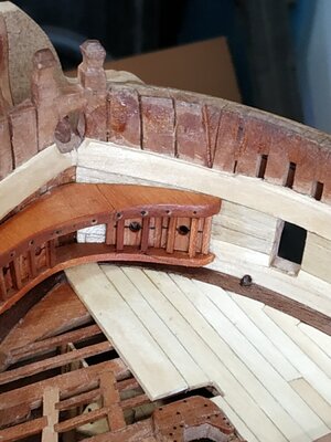
Hawse Hole Linings.
These holes are lined with wooden staves similar to a barrel, then lined with lead.
The final diameter of the hole (including lining) is given as 5.57mm.
I think I will skip the wooden part and just simulate the lead.

Breast Hook.
Thickness of 4.24mm, as others, boomerang-shaped. Lies horizontally with lower surface 17.49mm above the deck according to TFFM. This I found confusing as the deck slopes in both directions. Does it mean at the foremost point? Took measurements from plans but will fit after the neighbouring parts are made.

The Bucklers
(TFFM refers to this as an archaic term meaning shield-but some of us were brought up on “swashbucklers” in films, and I do not consider myself archaic !!)
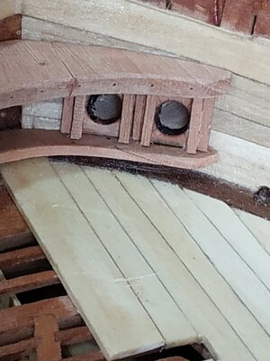
Anyway, these are coverings for the Hawse Holes on the inner Hull.
Thickness 1.33mm and horizontally divided into halves.
Outside dimensions do not appear to be given but I guessed at 10mm square, which allows holes to be centered and a Cant of 1.6mm sq. to separate the inner and outer Hole.
There are also 1.6mm sq.on either side and attached to the inner hull planks.
In front of the Bucklers, on either side of the hole, are Buckler Bars, of similar size as the cants.
I made a mistake in not converting these holes into metric and made them initially 4.5mm (the rope is given as 4.5 ins). Noticed only when fitted, and remade them to the correct 2.4mm.

Bolster
This is a boomerang shaped shelf supporting the above structures, 2.12 mm thick- rather like a slimmed down breast hook.
The Bucklers Bars are slotted into mortises on its upper surface, which match those of the undersurface of the Breast Hook. I have omitted this feature.

I fixed the position and glued the Breast Hook first, then the Bucklers, ensuring their holes align with the Hawse Holes, then the Cants and Bars. The Bolster then fitted beneath them.

Can someone tell me why, if the Rope is (real size) 4.5in and the Buckler Hole slightly larger, the Hawse Hole is 10.5in????


13222.jpg15a322.jpg
 
Sorry, I don't understand the question "the planking of the bridge planned?" The form or style of the deck planking is taken from TFFM, but I assume is based on plans or records of the time.
Good evening, you could tell me what this wording "TFFM" refers to. Thank you
 
Good evening, you could tell me what this wording "TFFM" refers to. Thank you
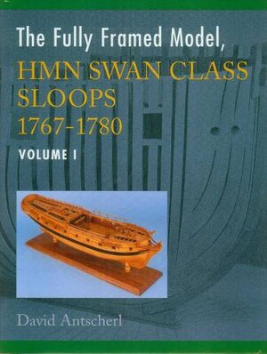
It is the short version of "The Fully Framed Model" book series by Antscherl

David Antscherl - The Fully Framed Model, HMN Swan Class Sloops 1767-1780

antscherlswan1title.jpg
 
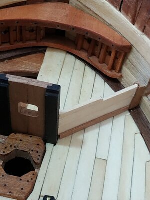
The Manger.
An area at the Bow. A low partition angles foreward from the Bowsprit Step Stantion to the Inner Hull planking, where they are fitted into a rabbet on a Cant, a post the height of the middle of the Hawse Hole.(12mm in my build)
This cant is 3.71mm sq. and situated just baft of its Scupper.
The planks or Manger Boards are 1.6mm thick.
They rest on a Rabbeted Manger Waterway which runs from the B.S. Stantion to the Cant.
The height of the partition drops about halfway towards the Cant.
I therefore made the partition with 2 board, with another of half the height for this taller length.

A simple build before tackling the Stove and its complications

16322.jpg
 
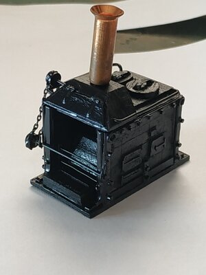
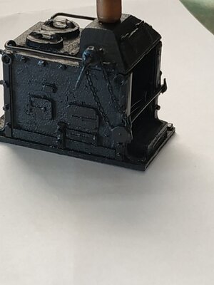
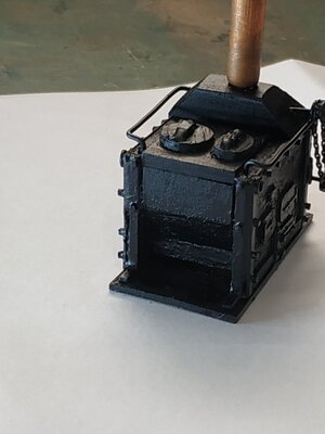
Galley Stove
As usual with TFFM read the instructions - 7+ pages.
The first suggestion is to study the drawings before reading the text !!!!
At first I was totally confused - Google images only made it worse and 3D rendering was too detailed for me to grasp initially.
I decided to get started by ignoring the fact that these were metal plates and considering how to get the finished product LOOKING like a stove.
The Stove rests on a Base Plate (not bricks) which fits between the Riding Bitt Standards,rests on the aft part of Foremast Partner and aftward according to my plans,43mm
It will sit on athwartship strips of wood to compensate for the curve of planking.
The 2 sides - I made overly thick (2.4mm), adding doors of 0.55mm veneer. Additional bits, hinges, wheels chain, from my leftovers box from old kits.
TFFM says check plan to see if the chimney is fore or aft when fitted. My Atalanta Sheer and Deck plan shows AFT, the Profile Plan , Foreward !!!
The forward and aft walls are not solid. Rather with inner partial, sometimes angled plates with a large opening beneath the chimney end.The other end,has the upper half closed, and lower open to recessed plates. These plates I made with1.4mm.
The side walls are framed in brass strip with “feet” extending forward and aft.
I stuck these walls to the BasePlate and made and placed those internal plates that will be seen from outside. The Drip Tray is milled out wood.
Couldn't make hinges small enough for the side doors- so just latches.
The top of the stove is divided into ⅔ for the boiler (with a round and an oval lid) and the lower chimney. The boiler is proud, so I used a 2.4 mm strip, milled ⅓ to half thickness, to sit flush to the side walls.
The lower Chimney is angled on each side. After several attempts to make this with the 1.4mm wood, simply took a solid piece and sanded it to shape as drawn.
The hexagonal nuts were cut from a strip of some plastic stuff, again left over from a kit.
Also the Grating Bars and supports from the bit box
The copper chimney just rests there temporarily to give the Stove a hat.
The whole thing is spray painted - this covers the copper without primer or colouring solution..
My wife thinks it looks OK -so I’m satisfiedIMG_20220321_145023.jpgIMG_20220321_145102.jpgIMG_20220321_145154.jpg
 
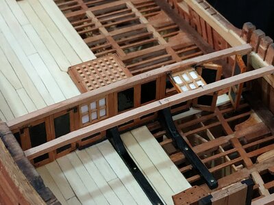
Forecastle Beams.

As the Forecastle Bulkhead sits beneath the 7th Beam, worth making the full set (7) now.
These are less substantial (presumably need to support less weight).
They are 3.45mm wide, and 2.65 deep., rounded up 3.18 over the full span of 14cms.
They are NOT Let Down.
Beam #3 scored for Bowsprit Chock

The Forecastle Bulkhead.

** I found delaying fitting of the Stove made access easier)
Sitting athwartships24322.jpg24b322.jpg24c322.jpg25322.jpg27322.jpg28322.jpg28a322 (2).jpg and just forward of Riding Bitts, whose Spurs pass through openings in them.
It also sits beneath the 7th forecastle beam to which it is attached, allowing removal as required.
The thickness of the Bulkhead is given as 1.6 mm.
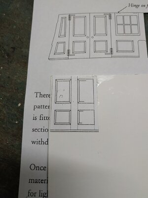
TFFM suggests using extra thin plywood, which I don't have, so used card as the center of the “sandwich”.
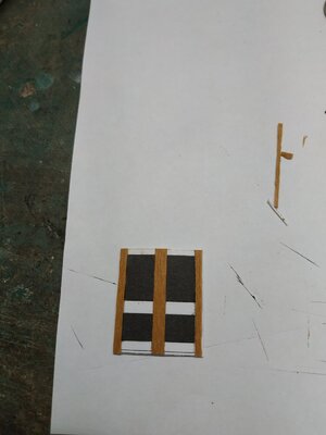
The pattern provided fits pretty well except for some adjustment at the wall. So divided into sections, the pattern glued directly to the card. Instead of colouring the panels, used cartridge paper (known locally as “Bristol”). The result is recessed, but looks OK.
Framing with beach Veneer (0.55mm).Process repeated on the other side.
The panel, other than the doors, sit on a grooved rail or Cant. The suggestion that this is made in halves, the panels resting directly on the deck. Also suggested that the pieces are chamfered, but using 1mm sq. strips, easier said than done. The foremost set was placed before the panel, the aft later. In future I will place both after the Panels are fitted
( A strip of planking used to level up the uncovered deck.)
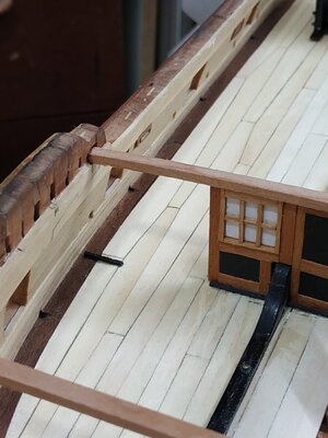
The central panel fitted- the straight sides give good reference to the next “window” panel.This includes the Bitt openings.
Windows framed by 1mm sq strip.
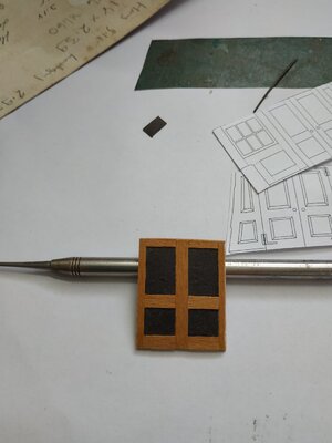
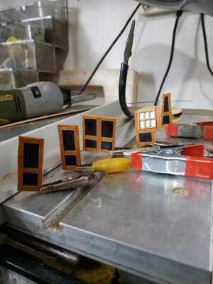
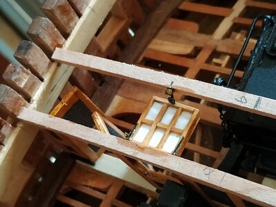
Choice to cut out the windows and leave open, replace the card with clear plastic before framing or leave with the white of paper pattern.Previous experience sticking wood to clear plastic was messy. I have a problem also with sticking small metal objects, such as hinges, to wood. Minimal cyano often fails. More is messy. The 5 min Epoxy is too thick to use a minimal dot. ADVICE and suggestions required and welcomed.
The port window is hinged and held open by a “hook and eye” on the side of the #6 Beam.
The doors are made in one piece and then divided down the center. The hinges were part of the photo etched set I bought. The door handle is the head of a pin.
 
Pillars and Stanchions for the Chain Pump Axletree.

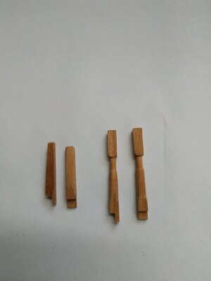
2 pillars aft edge of Aft Hatch
Made from 3.71 mm sq stock. Turned as per pattern. Left over long until fitted beneath the deck beam. Hole for passage of Axletree, also left until Axletree made.
Note slope of notched foot to match tapering of coaming.
2 corresponding Stanchions at fore of Main Hatch -squared, tapering upward.
Options for bracing, will go with wood Cross Brace as mentioned

Rhodings.

Previously made along with the Bitts.
Now they look pretty pathetic. Also will be remade after Axletree determines their position.IMG_20220329_103034.jpg
 
TFFM- The Fully Framed Model
It's time again to give thanks to these volumes and their author David Antscherl.
To me, and others, it is an essential base for scratch building model ships in general, and the Swan Class in particular.
It isn't just a “how to”, but an education in the vocabulary and often history of the details of ship building as was, and modern model making.
Not only is it enjoyable to read and learn, but it makes it possible for someone like myself, with little artistic talent and craftsmanship, to produce something that I could only dream of, when reading the books and blogs of modelmakers.
Thank you.
Just bought all 4 volumes plus an additional sails booklet. Seawatch use to sell plans for those books on a scale of 1:48. Does anyone know where to obtain plans accompanying books? Mike (new owner) offered a 25% discount, it is the perfect time to hunt for the books you always want.
 
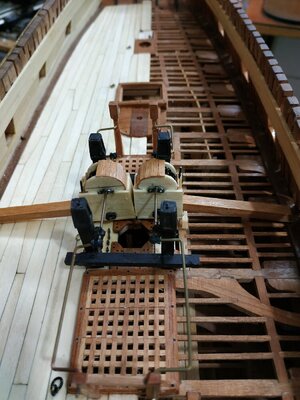
Chain Pump Head Gear
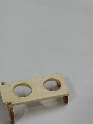
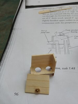
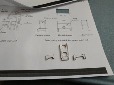
The Cisterns.

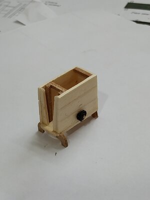
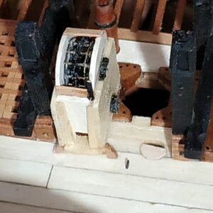
These are wooden boxes covering the Chain Pumps where they protrude through the deck.
They sit on curved legs-the inboard which are shorter as they rest on the Main Mast Partner.
The base is 1.06mm with holes for the tubes.It should sit 5.83mm above the planks.There is little room for the inwards as the port and starboard Cisterns are “back to back”.
The pair of sidewalls are formed by planks of similar thickness.The ends taper slightly inwards.
The height is 15.9, the length and width to fit the Base
The inboard end is similarly made,and closes the rear of the box.
The outboard end is partially open with a shaped pair of “doorposts” tapering upwards. This allows a square drainage tube, the Pump Dale, to fit between.
To the side and above the Dale where it enters the Cistern, is a Slide, which is the same hight as the other walls.
Behind the Slide, is another pair of “door posts” to hold it in place. These, as well as cross-bracing pieces at both ends, are 1.6mm
Overall widths and heights are given for the assembly, 10.6mm and the top edge is maximum 43mm above the deck. This meant some shortening of the legs in my build.
On the fore side us a circular DrainHole 4.77. After several failed attempts to drill and file this out, I made the plug and pinned it into position.
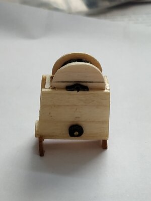
The Cistern Hood.
Semicircular sides, again 1.06 width, fit within the cistern walls. The ends are notched and rest on the Cistern cross pieces. At the lower center on both sides are cut outs to allow the Spindle of the Sprocket wheel to pass through.
The Top to be fitted after the Sprocket Wheel.

Sprocket Wheel.
Suddenly remembered that there were bits on my photo-etched sheet that were for this purpose.
The 2 disks are separated by 12 bolts, for which I used particularly thin pins I happened to have. They extend outside the disk by 0.5mm. The whole assembly fitting snugly within the Cistern Hood.
CHECK BEFORE GLUING.
The spindle itself was 1.6mmsq wood, long enough to support the Wheel on the Cistern side walls.
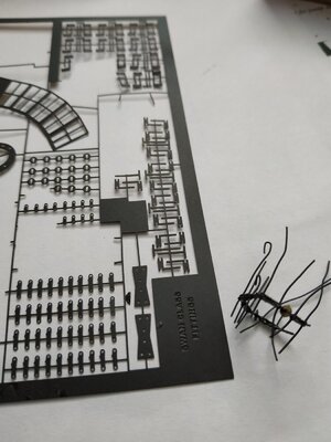
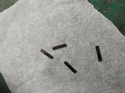
The chain also was made from the pieces on the photo-etched sheet.
They consist of thin plates (Links) bolted in pairs, and connected by a 3rd plate between them . Sort of 2-1-2-1-2 formation. For bolts,.25mm, I used copper wire, trimmed after gluing.
I cannot solder at any scale, especially this, so I used Cyano super glue.
There is fitted a disc, representing a leather washer or Saucer, on a single link every 19mm or so.
I did not attempt threading the links down the pump tubes. Rather draped it across the Sprocket Wheel.
The Cistern Hood was partially covered to display this mechanism. It was apparently a real feature. The covering slats are 0.4 boards.
A vertical metal tongue works a latch to allow this partial opening.
29322.jpg30322.jpg30a322.jpg30b322.jpg30c322.jpg31322.jpg31a3220.jpg
 
Upper Deck Bolts
There are various deck Bolts - Fit these now because access after completion of Axel Trees and Winches is very limited. They are shown on the decking patterns and in ch.9 for those on the Main Mast Partners.

AxelTrees and Winches.
Can’t find the diameter of these, but if the Rhodings have an inner diameter of 0.8mm, presumably slightly less than this.
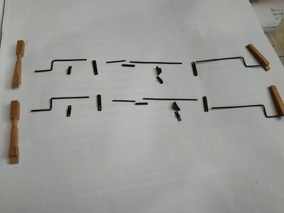
Tried to use coated copper wire, but after several attempts, the result was unsatisfactory. It is difficult to keep them straight, with all the handling the build requires.
I also found my attempts at fabricating the couplings were unsatisfactory.
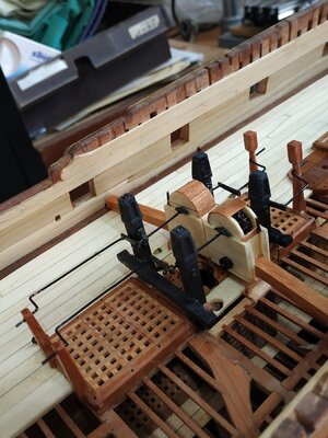
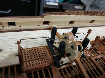
For my last attempt, I used a 0.95mm ?brass rod - more rigid- bending them to 90deg. For the couplings, and making only one joint between the winch and AxelTrees, where it is shown to be enlarged and square. Couldn’t replicate it, so used some tiny barrel shaped bits of soft metal, and drilled holes at right angles.
Holding the parts in place while glue dried was very frustrating. Making the whole “off”model and then fixing was tried and failed. Perhaps shortening the Sprocket wheel spindle would allow the winch handles to move into the Cistern Hood while maneuvering the whole into position.
I WOULD BE MOST APPRECIATIVE IF SOMEONE CAN ADVISE ME.
For the Rhodings, I used some Capsquares from my spares box.
The Rhodings on the Main Topsail Bit require a spacer as these Bitts are more widely spaced.
(A most frustrating and unsatisfying few days. Next on the build list, is the Capstan. That should really be a test- but at least it's wood!)3422.jpg3a422.jpg3d422.jpg3c422.jpg4422.jpg7422.jpg7a422.jpg
 
Upper Deck Bolts
There are various deck Bolts - Fit these now because access after completion of Axel Trees and Winches is very limited. They are shown on the decking patterns and in ch.9 for those on the Main Mast Partners.

AxelTrees and Winches.
Can’t find the diameter of these, but if the Rhodings have an inner diameter of 0.8mm, presumably slightly less than this.
Tried to use coated copper wire, but after several attempts, the result was unsatisfactory. It is difficult to keep them straight, with all the handling the build requires.
I also found my attempts at fabricating the couplings were unsatisfactory.
For my last attempt, I used a 0.95mm ?brass rod - more rigid- bending them to 90deg. For the couplings, and making only one joint between the winch and AxelTrees, where it is shown to be enlarged and square. Couldn’t replicate it, so used some tiny barrel shaped bits of soft metal, and drilled holes at right angles.
Holding the parts in place while glue dried was very frustrating. Making the whole “off”model and then fixing was tried and failed. Perhaps shortening the Sprocket wheel spindle would allow the winch handles to move into the Cistern Hood while maneuvering the whole into position.
I WOULD BE MOST APPRECIATIVE IF SOMEONE CAN ADVISE ME.
For the Rhodings, I used some Capsquares from my spares box.
The Rhodings on the Main Topsail Bit require a spacer as these Bitts are more widely spaced.
(A most frustrating and unsatisfying few days. Next on the build list, is the Capstan. That should really be a test- but at least it's wood!)View attachment 301221View attachment 301222View attachment 301223View attachment 301224View attachment 301225View attachment 301226View attachment 301227
My dear friend
as usual, you are doing amazing things it's looks beautiful, well done
 
Can someone tell me why, if the Rope is (real size) 4.5in and the Buckler Hole slightly larger, the Hawse Hole is 10.5in????
My understanding is that the excess space in the hawse hole was stuffed with 'junk' (old rope) or rag to help drain some of the water and debris off the cable as it was winched in. Otherwise all that mess ends up inboard.
 
Back
Top