• Ships of Scale has incorportated an extra level of security when you log In. Please follow on-screen prompts to acknowledge that you are not a robot via a "Check Box" or a "Pictorial Check Box Puzzle". This is needed due to higher level of AI Activity Security.
  • SUBSCRIBE TO SHIPS IN SCALE TODAY!

    The beloved Ships in Scale Magazine is back and charting a new course for 2026!
    Discover new skills, new techniques, and new inspirations in every issue.

    NOTE THAT OUR NEXT ISSUE WILL BE July/August 2026
  • Win a Free Custom Engraved Brass Coin!!!
    As a way to introduce our brass coins to the community, we will raffle off a free coin during the month of August. Follow link ABOVE for instructions for entering.

The Black Swan by OcCre 1:75: Build Log

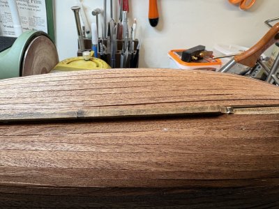
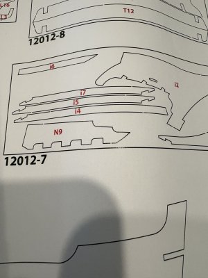
The next step is to attach the pieces that represent the keel. In order to do that you have to make sure the "keyway" which it attaches to is wide enough. I test fitted the pieces and had to widen the slot with a file in a few places for the pieces to fit.
IMG_0023.jpeg

Just a note in the diagram of the pieces the keel pieces i-4 and i-7 were incorrectly labeled. They should be reversed. But it is pretty obvious that this is an error
IMG_0033.jpeg

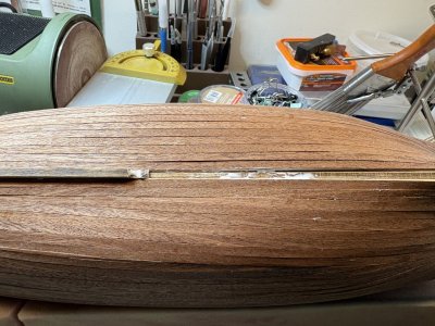
The keel pieces nicely key into each other.
IMG_0025.jpeg

IMG_0026.jpeg
 
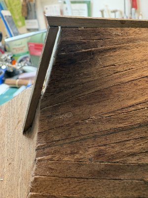
The sternpost presented a bit of a problem. While the photo in the instructions show it fitting tightly, it stands out with a large gap if sitting without any modification.

IMG_0027.jpeg

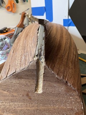
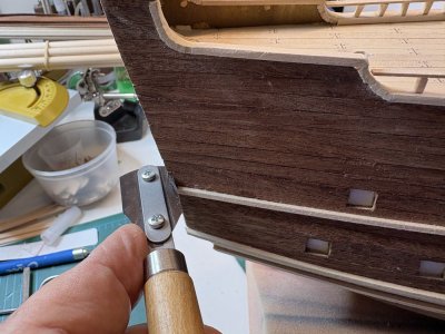
I traced along the outline of the post and using the "Chisel" blade of the x-acto knife I slowly chiseled out an indentation to fit the sternpost into.

IMG_0030.jpeg

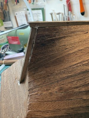
This allowed for a much better approximation of the sternpost to the hull.

IMG_0031.jpeg

I will fill the remaining small gap with wood filler.
 
Last edited:
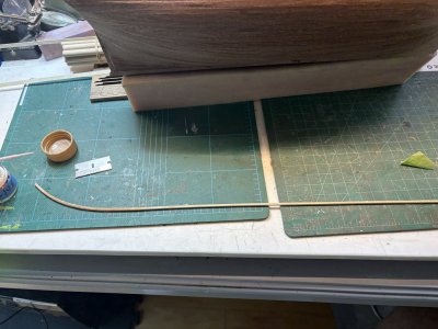
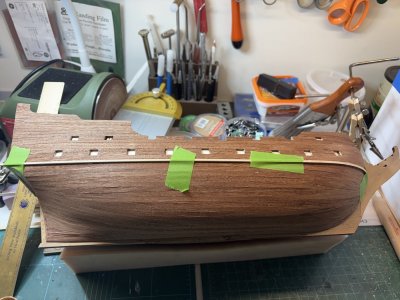
The next step is to install the wales. Two, 2mm x 2 mm strips are used with a 1x5mm strip between them. Before installing the 2x2mm strip I soaked a portion of it for a few minutes and curved it with my sealing iron.

IMG_0037.jpeg

This was then glued into place. I used tape instead of trying to figure out how to clamp it in position to let it set.

IMG_0038.jpeg

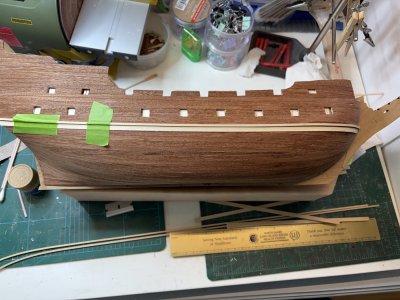
The wider strip was then added.

IMG_0039.jpeg
 
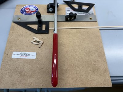
Next is to set up a railing that goes above the bulwarks. Some 1mm x 3mm "stanchions are cut out. To cut them I use my chopper with makes quick work of making duplicate same length pieces. I also used it on other portions of the build when I need a lot of the same length strip.

IMG_0041.jpeg

The 1mm x 3 mm stanchions were glued into place.

IMG_0043.jpeg

To make the railing 2mm x 6mm strip is cut to length. I found the lengths suggested in the parts list were in most part in error, so I measured each individually.


IMG_0045.jpeg


Note the curved part of the railing is a series of 2mm x 2mm strip that is cut to 6mm length and then sequentially glued along the curve of the bulwark. I again used the chopper to make the required amount. I think it would have been much better if there were laser cut pieces. However that would have required a 6 mm depth of the wood to be laser cut. (of course they could have used 2, 3mm or even 3, 2mm laser cut pieces glued together to make a more esthetic curve).

IMG_0046.jpeg
 
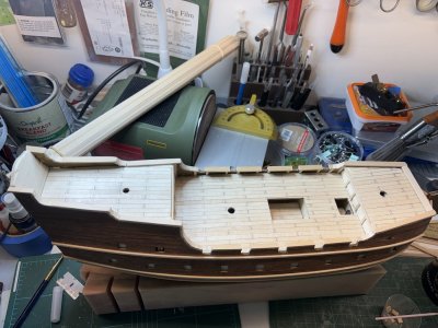
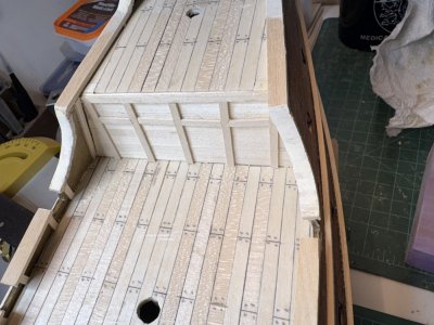
Finishing up the railing, I had just enough of the 2 x 6mm strip to do the decks except for the rear.

IMG_0051.jpeg

However I was in luck, as you may note the transom piece kind of blocks the rail piece from going the full 6mm. I used some 2 x 5mm left over pieces and they fit just right.

IMG_0052.jpeg

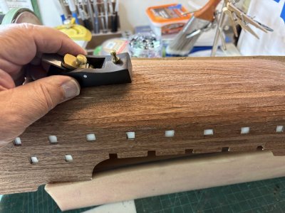
After everything had set. I cut out the railings over th gunport openings as show. I also sanded smooth the curved area that was made using the 2 x 2mm pieces. This improved the looks but I could be happier with some pieces designed to belong there.

IMG_0054.jpeg
 
In order to make the curved parts of the rail smoother, I used Elmers wood filler letting it set and sanding it. It really improved the look.

IMG_0059.jpeg


I started to glue on 2 x 2 x 5mm Stanchions into place. I used a piece of scrap cut to 10mm as a spacer.

IMG_0060.jpeg
 
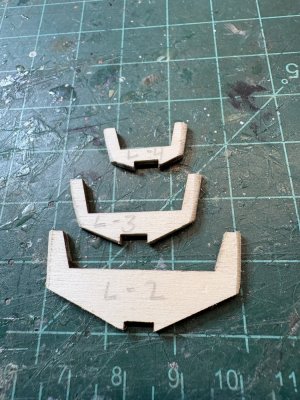
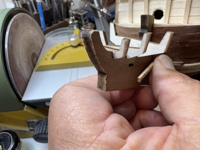
On to constructing the forecastle. There are 3 small "bulkheads that go forward. they are supposed to be faired after they are put into place but look fairly delicate. I belveled the fronts of them before I set them into place to help prevent them from breaking.

IMG_0064.jpeg

The notches they are going into are fairly long and there is not a positive fit. Looking at the assembly pictures they look like the "lean" forward in the slots so I glued them and put them forward against the front of the slot. You also have to make sure they are square side to side as the set in place.

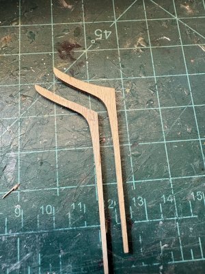
Each side gets two curved pieces that go from the hull out to the figurehead area. These are laser cut pieces. The problem with these is the curve that goes along the hull is not enough to let the other piece attach where it is suppose to be on the head.

IMG_0065.jpeg

The curve on the piece had to be leveled out. I did this using my dial sander and slowly taking off more and more.

IMG_0067.jpeg

The lower piece was sanded down to enable a tighter fit.
 
After test fitting, the curved pieces were glued into place. Below thew curved pieces 2 strips of 2 x 2mm strip is placed.
IMG_0068.jpeg
The 2 pieces are suppose to be 5mm apart. The upper strip is place adjacent to the lower curved piece. In order to space the pieces I placed a 5mm scrap strip between the 2 pieces to act as a spacer.

IMG_0069.jpeg


IMG_0070.jpeg

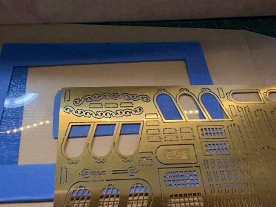
A Photo etched (PE) scroll work piece is suppose to lie between the 2x2mm strips. A sheet of photo etched brass is supplied. It looks well made and it thicker than the PE I am used to. To cut out the PE I usually use a piece of old glass that I attached a piece of masking tape. If you cut the PE on a cutting mat it usually results in the PE being pushed into the mat and distorting. Using masking tape on the glass helps prevent the piece from spring away into the dreaded void of the carpet monster, never to be seen again.

IMG_0075.jpeg

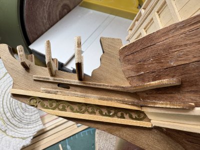
The scroll work fit perfectly between the strips.

IMG_0076.jpeg
 
Last edited:
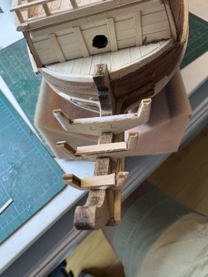
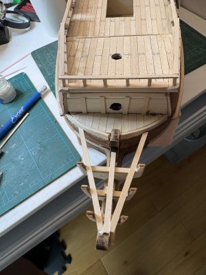
They would next have you do the railing along the head followed by the platform (or walkway?) I always think it is usually easier to build from the inside out so I made the platform first from some 1x3mm strip.

IMG_0080.jpeg

IMG_0085.jpeg

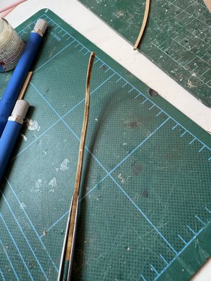
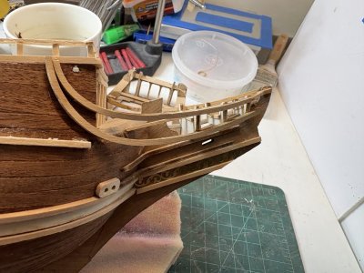
The curved pieces of the "railing" are laser cut. While the instructions show them just fitting into place, the certainly didn't do that for me. They had to be bent to fit both the hull and the "bulkheads" along the head. These pieces, being made of thin plywood do not want to be curved and break easily (don't ask me how I know this :rolleyes:). After several frustrating tries I soaked the pieces and bent them while wet.
IMG_0086.jpeg

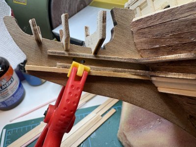
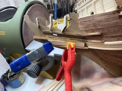
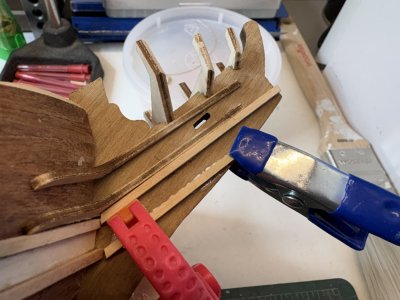
I tnen clamped and taped them in place while they dried. They were then glued into place. So far this had been my most frustrating part of the build.

IMG_0093.jpeg
 
Last edited:
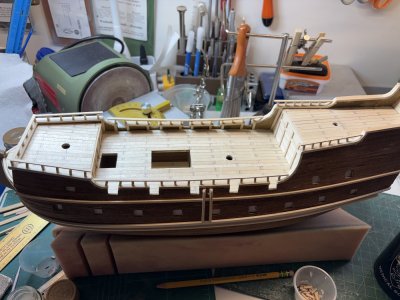
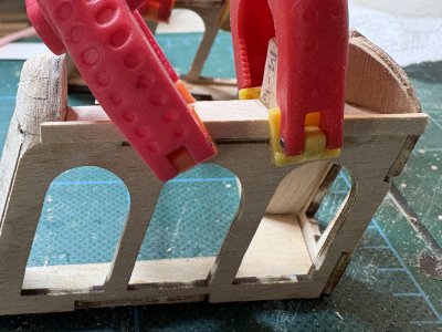
While waiting for the pieces to dry I started the next part which is the captains cabin which hangs off the back of the ship. This is assembled using laser cut pieces.

IMG_0088.jpeg

IMG_0089.jpeg

IMG_0092.jpeg

A few pieces needed their tabs trimmed a bit to fit well. Other than that everything seemed to fit into place.
 
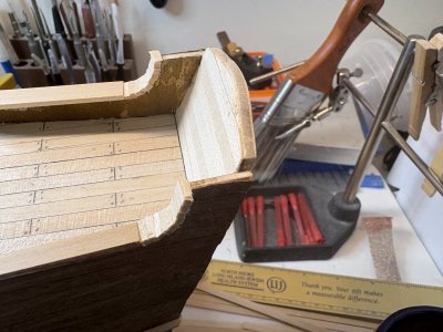
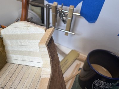
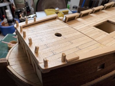
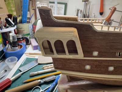
The upper part of the captain's cabin is covered with strips of 1 x 3mm strip. The front part is a curved corner that the instructions would have you carve out of some 4 x 4mm pieces glued together on the top. I thought that this could be done better. I decided to use some of the large amounts of 2 x 6mm and 2 x 5mm strip I had left over from other work on the ship. I cut and stacked the pieces to minimize the amount of carving I would need to do.

IMG_0232.jpeg

I will let these pieces dry overnight.

They also wanted you to cut a slot on the rear of the hull to allow the cabin to slot into it. I did this using a razor saw.

IMG_0233.jpeg
 
Last edited:
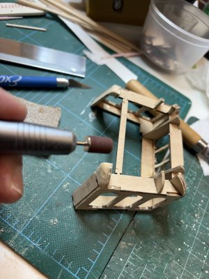
After the 2x 6mm and 2x5mm strips dried I shaped the corner using sandpaper and my nail drill.

IMG_0237.jpeg

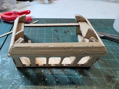
I started to apply the upper strips to form the ceiling of the cabin. I did some mitering of the corners.


IMG_0238.jpeg

IMG_0239.jpeg

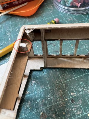
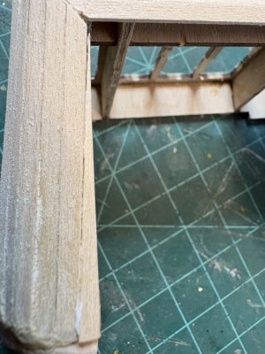
One of the forms that the strips wrap around was too tall. and caused that part of the strip to bulge out. (circled area) I sanded it down until the strips fit evenly. I also beveled the upper strips as they would adjoin the lower strips, much as you would when planking a hull.

IMG_0240.jpeg

I also started to use wood filler to smooth the walls and the area between the strips. I test fitted the cabin to make sure it would fit.

IMG_0241.jpeg

There is a gap on one side that you can not see. I will put in a piece of 2 x 3mm strip similar to using a stealer on the hull.
 
Thank you Grant. To be honest this is not my favorite build. I think the online video and the pictorial guide they include is not the best way to do this. There are a lot of inconsistencies. For instance it appears they want you to tape off the area where the captains cabin will go and paint the area black so you can not see details inside. Later on they have you paint the whole upper hull black. Why bother taking the time to tape off a specific area if the whole thing is going to be black?

I also did not like the planking without a rabbet, although I know it is not that unusual. I have a lot more joy in the my building of the Bluenose.
 
Last edited:
Thank you Grant. To be honest this is not my favorite build. I think the online video and the pictorial guide they include is not the best way to do this. There are a lot of inconsistencies. For instance it appears they want you to tape off the area where the captains cabin will go and paint the area black so you can not see details inside. Later on they have you paint the whole upper hull black. Why bother taking the time to tape off a specific area if the whole thing issuing to be black?

I also did not like the planking without a rabbet, although I know it is not that unusual. I have a lot more joy in the my building of the Bluenose.
Good morning Rob. Such is ship building, we definitely have our favourites and not so favourite builds (My Bounty (although a redo) has been one of those)..........so much is kit depending. More often than not I tend to deviate from the kit instructions very early. Cheers Grant
 
Back
Top