Great information, thanks for posting.
Bill
Bill
 |
As a way to introduce our brass coins to the community, we will raffle off a free coin during the month of August. Follow link ABOVE for instructions for entering. |
 |
 |
The beloved Ships in Scale Magazine is back and charting a new course for 2026! Discover new skills, new techniques, and new inspirations in every issue. NOTE THAT OUR FIRST ISSUE WILL BE JAN/FEB 2026 |
 |

As stated before Rich, I have a republished copy of this book and utilized it extensively. I made my choice not lightly. within this very book it states that GR was rigged with Forbes double topsails. In a separate article, I have Forbes is quoted as saying she did NOT have his design....and Forbes was a close friend of McKay.These pages are courtesy of the SOBCO website. Cover is from Eldred's which lists this publication for $1,500.00
I realize the topic of skysails on individual masts has been a somewhat, almost silly "bone of contention." This document will only add fuel to that smoldering fire. While the sail plan shows them installed on fore and main, spar specifications call for skysail yards on fore, main and mizzen! Building her as ultimately planned gives a would-be modeler exact details to accomplish it. Then again, modeling her as she appeared in New York Harbor is another option. Ironically, either choice is accurate.

Bill,Great information, thanks for posting.
Bill

Rob,As stated before Rich, I have a republished copy of this book and utilized it extensively. I made my choice not lightly. within this very book it states that GR was rigged with Forbes double topsails. In a separate article, I have Forbes is quoted as saying she did NOT have his design....and Forbes was a close friend of McKay.
The fly in the pudding is...the very drawing we are looking at here of her sail plan does not show her with the Forbes design....but a *modified* version. Forbes design places the topsail mast abaft the main mast doubling. It is clear this is not represented in this drawing. I get the sky sail thing. N.B. Palmer..who eventually purchased and rebuilt GR, was also a friend of McKay, and his own recollection states that when the GR was on display in NY for visitors to view, while she was awaiting her cargo to be deployed...she did NOT fly any sails higher than the royals. Now that is all good and such........but as you say...how she was designed and how she was displayed can be two different things all together.
Well...this has been an education, however, Norgale, doesn't appear to be interested in our little nitt picking sidetrack.....so I'm bailing out and simply watching from here on out.
Rob

Norgale,I hadn't expected to get to read the whole publication but there it is. Thanks for that Clipper Fan. I will print and study that with much interest. Norgale
By the way controversy is a good thing. Without it nothing gets improved.

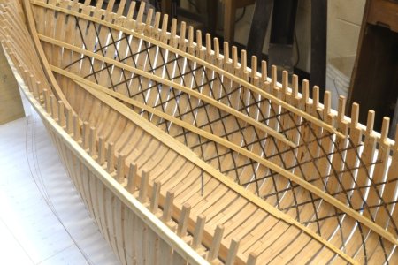
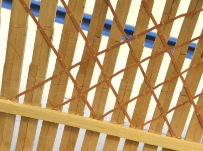
Norgale... Pete, I also go by Rich. We're supposed to select on-line IDs, hence "ClipperFan." Back in the early 2000s I met a wheelchair bound retiree. I complimented him on his 3 bay open structure garage which had no internal lolly columns for support. The structure looked just as sound as the day he built it 40 years earlier in the 60s. The roof inside was an amazing lattice work of 2 x 4 trusses. He was a retired structiral engineer for the town of Morris. He then directed me to another huge multi bay garage that was 40' × 20.' He invited me to inspect the interior. Again, no lolly columns to be seen anywhere. The entire space was wide open and above was an another incredible spider like network of reinforcing trusses. Nothing was larger than 2× 4s. The massive bay was built in 1967 and was arrow straight. He said the use of trusses, all calculated by hand on slide-rules had become a lost art. He also said 2 × 4s were sufficient. Anything larger was overkill. It's the reinforcing trusses that make all the difference. That's what these nicely detailed images of the elegant trusswork in the clipper ship Great Republic rreminds me of.Hi ClipperFan and thanks for the reply. You have hit on the exact problem with a very large scale. The real ship would have structure sufficient to hold it together and then some because the water it sets in will hold it up all the way under the hull and partway up the sides. A static model will be totally unsupported for it's entire length ,so I reasoned, the strength inside the hull needs to be enhanced to keep the hull shape and provide strength to move it from place to place. That's why my keel and wing keels are a bit over sized and the deck beams are too. The keels give horizontal strength and the deck beams give lateral strength. Also the keels were laminated and screwed together for additional protection against warping. Lets hope that works. Another thing that was done is fashioning a clamp for the whole thing at the exposed part of the keel at the very bottom. I made a simple structure of boards that offered a clamping action against the whole keel to keep it straight during the build. The clamp is perfectly straight and level as are the building benches under it. That's about as good as I can make it so I hope it works as intended.
Since all the frames are less than perfect side to side there developed a problem with lining then all up fore and aft and side to side. That's where I threw away the second attempt at the frames and redesigned the frames and did the work over again. A CNC machine would be extremely helpful in cutting frames equal on both sides rather that doing them by hand with a band saw. Getting the frames equal was the hardest thing about this build and the most important thing too. The frames had to be made bigger than true scale so that fairing the outside hull will offer enough material to sand and fair before planking. I only use about 30% of the number of frames that the real ship had so some spaces where the lines bend around a lot will not measure out right. These are just a few of the changes that I felt had to be made to accommodate the size and weight of the model. Because of these problems and my inexperience at models of this stature I've made a few Laisse' Faire changes to help me get past a particular problem and still come out with something that resembles a ship. Actually I don't expect this model to be anything but a mantle ornament but the next build will be much better I hope. I do try to keep dimensions as close as I can and the measurements in the book you posted will go a long way toward that end.
I appreciate your advice and Rob's too, very much. I hope you will both continue to advise me. Pete



Roger,Go to the Model Ship World Forum and look up Ed Tosti’s build log for the Clipper Ship Young America. If I remember correctly he added strapping to his hull.
I personally see no reason to add the strapping if you plan to completely plank Your hull. I believe that your hull will have adequate longitudinal strength without it. First of all your hull is not going to be subject to cyclical hogging and sagging loads like the real ship. Second, your hull will probably be stronger than that of the real ship. This is because you are able to glue together members of the hull girder whereas McKay had to rely on mechanical fasteners that could work loose under cyclical loads. You can also add external supports to display the model.
The planking is not the principal strength member in a wooden ship. The real strength members are the keel and keelson forming the bottom of the hull girder with continuous decks forming the top. The iron strapping installed diagonally to the outside of the frames was there to resist shearing loads that would work the caulking loose and cause treenails to fail. Construction of these Clippers occurred just as British Civil Engineers were able to rationally understand the longitudinal strength of these large structures. While
Roger
Hey Roger and thanks for your interest in my project. I love the pictures you have posted but I could never bring myself to put too much store in a painting. I don't know how much the artist knew about sailing ships in general and specifically the subject of his work. Looking at a ship at anchor you may see a lot of rigging but not see all of it. How do we know he got all the ropes correct and if the rake was zero how did the artist get the rake in the picture? When it comes to that, how do we know that the plans and "eye witness" accounts of the GR's measurements are correct? Even if we go by the descriptions of McKay himself, how do we know the ship was all built the way it says in his book. My answer to all that is , we don't. Otherwise there wouldn't be so many different interpretations of the work on the ship. I decided back in January when I started this build that I would go by the plans that I have and the instructions that I have in the book by Crothers and go from there. I also found that Clipper Ships were all mostly rigged alike. At least the basics were pretty much the same including the ships made in Europe. Having made a 1:78 model of the Cutty Sark ( and not yet finished it) and compared the plans for each with each other I find they are very much alike. Lord knows that the Cutty Sark has been examined from stem to stern and it's plan has to be as close to correct as anything can get today. Of course there are details that are not the same so they must be taken into consideration by the model builder. Like not sanding down the frames on the inside. By not doing that I had to change the lay of the ceiling planks in several places to leave all the "meat" on the ribs for sanding the outside. Consequently the ceiling is a hodg-podge of mistakes and unoriginal lay of the planks. I have frames that are not perpendicular to the keel, there are frames that are not equal on both sides, some frames are not long enough at the top and some that are too long at the top and I still haven't decided what to do with the stern framing yet. That's why this project has held my attention for so long. It's a constant challenge to my skill to be able to arrive at a completed model that looks like the GR. As I stated before anybody who knows anything about the GR and can look at my model and say "That's the Great Republic" then I will have done my job as I see it. If they do know the ship and don't identify my model as the GR then I have failed. With the deck furniture on and a full set of sails there shouldn't be any confusion. So let's see how it turns out. Incidentally I've decided to skip the iron straps because that was installed to help prevent or at least delay hogging of the bow and stern on the real ship and I don't expect to have that problem with the model. As for the rake, I'm setting the masts at 8? degrees because I like the looks of it and it appears more often than not. There. All that is now decided. I feel better too. Just don't tell the rivet counters.Go to the Model Ship World Forum and look up Ed Tosti’s build log for the Clipper Ship Young America. If I remember correctly he added strapping to his hull.
I personally see no reason to add the strapping if you plan to completely plank Your hull. I believe that your hull will have adequate longitudinal strength without it. First of all your hull is not going to be subject to cyclical hogging and sagging loads like the real ship. Second, your hull will probably be stronger than that of the real ship. This is because you are able to glue together members of the hull girder whereas McKay had to rely on mechanical fasteners that could work loose under cyclical loads. You can also add external supports to display the model.
The planking is not the principal strength member in a wooden ship. The real strength members are the keel and keelson forming the bottom of the hull girder with continuous decks forming the top. The iron strapping installed diagonally to the outside of the frames was there to resist shearing loads that would work the caulking loose and cause treenails to fail. Construction of these Clippers occurred just as British Civil Engineers were able to rationally understand the longitudinal strength of these large structures.
Roger
Why does this ship fly two American flags? I always thought one at the stern was proper. Your right about the colors. They really are beautiful.Norgale,
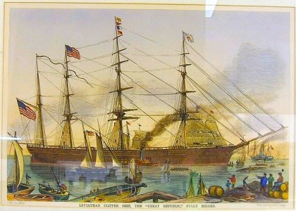
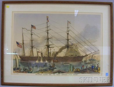
Besides Gleason's Pictorial black and white lithograph, there was another hand tinted version. I found this framed copy on a Skinner advertisement. I've edited and lightened the original so it can be viewed better. Other than the beautiful colors, it's the identical print. I just thought you might appreciate the beauty of it.
View attachment 479372
View attachment 479378

Norgale,I've seen buildings like that back home and I studied Architecture for a few years so I get your point. However it's kinda late now to re-reinfore my hull but I could add the iron strapping I think. What would you use for the strapping? Was the strapping put inside under the ceiling or was it on the outside under the planking>? I'll have to fair the frames first and then let the strapping into the frames so they won't interfere with the outside planking and that's a lot of extra work that will never be seen.But it may provide extra strength to the hull so it won't hurt anything by adding it. If it can go on the outside under the planking it could still be done.


Norgale,Why does this ship fly two American flags? I always thought one at the stern was proper. Your right about the colors. They really are beautiful.
Norgale accepts "all due respect" and I will follow the available instructions as close as I can. However you can see from the pictures that I go according to my instincts when the plan gets confusing. I have never done so much planking on one hull in my life so the inside ceiling was a good place to practice even though there are a million mistakes. When I'm finished you won't see any of them but they will all help hold the hull together. By the way , what is SOBCO and where is it?Bill,
You're welcome. My thanks too to Scott's excellent SOBCO website, which has links to all six highly desirable engraved illustrations.
Here's a few other observations I've made where the actual ship's illustrations differ from McCann's who does his own beautiful yet inaccurate illustrations. Biggest discrepancy are masts on the ship as illustrated follow traditional layout, not reversed topsail masts. It appears that McKay adapted the Forbes design with his own innovation. Other differences are her jibboom narrows but enters into the hull similar to Glory of the Seas instead of terminating just outside the hull. There is indeed a splash rail at the Great Republic bow, illustrated on sail plan engraving number 1. Multiple portholes in the Currier litho are confirmed in page 10 of her general description. Finally, there is indeed an ever so slight rake to the three forward masts, with the fourth jigger mast having a more pronounced rake as seen in the cross-section engraved illustration 3. With all due respect to Norgale, I figure anybody building a large model can only benefit from having the most accurate resources to rely on.
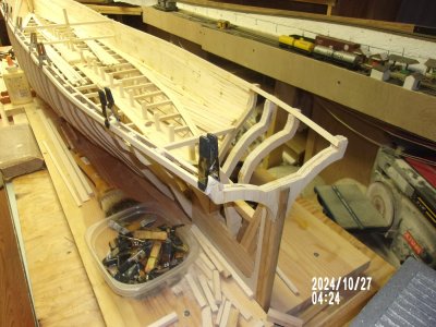
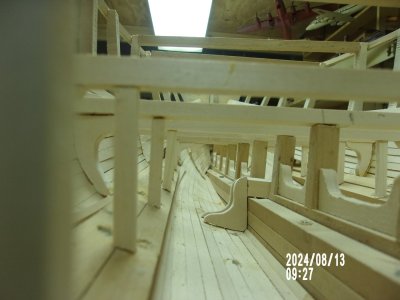
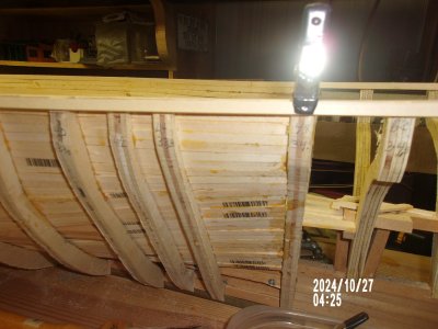
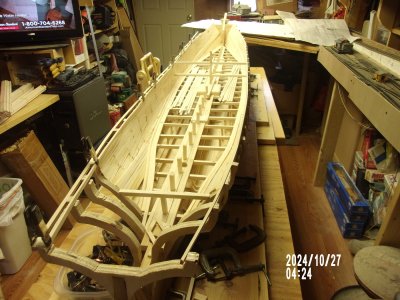
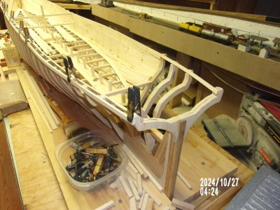
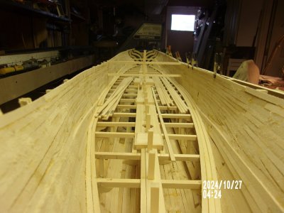
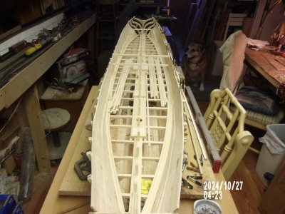

Norgale,Norgale accepts "all due respect" and I will follow the available instructions as close as I can. However you can see from the pictures that I go according to my instincts when the plan gets confusing. I have never done so much planking on one hull in my life so the inside ceiling was a good place to practice even though there are a million mistakes. When I'm finished you won't see any of them but they will all help hold the hull together. By the way , what is SOBCO and where is it?
By the way another publication I'm using is one from Nautical Research Journal, transcribed by Lars Bruzelius in 1996. It contains many articles by several different authors including the writings of Donal McKay that I use to verify items in William Cruthers book of Clipper Ships. Very informative.

Norgale,It's Sunday again and time for another update on The Great Republic. This past week saw the Lumberbird take a dump at my house with a bunch more bass wood strips for the GR. 300 pieces to be exact but they won't last long since it takes 3 and a half pieces to lay one line of planking the length of the model. It will at least allow me to finish the inside ceiling up to the plank sheer and to get the two sides level and as equal as possible. I was surprised that the level of the two sides cam to within 1/16th of an inch the length of the model. That makes it a lot easier to smooth out the sheerline on both sides. The frames are of different thicknesses but they will sand out with plenty of material left on each one.
As soon as I get the sheerline leveled I will start in the lower deck. I know I'll get some comments on the way I plank that deck but I'm not going to make separate pieces of the deck and show all the lines for each piece. I will use full length pieces of lumber for strength and spile the pieces at the ends to merge with the adjacent pieces and practice my spiling for the outside of the hull.
The plank sheer line has been carried out to include the stern so there is that to base the stern finishing on. The bow ceiling ends short of the bow itself because of the frame thickness but I don't see that as any problem. I think I will dispense with adding any more cargo in the hold. It will take way too much material to make it look like the boat has a cargo in it and the weight will be a lot to add to the hull. Since it will all be hidden I will add only a few items here and there as I build up the decks and call it a day.
Here are a few more pictures of the progress as of today.View attachment 480515
View attachment 480516
View attachment 480518
View attachment 480519
View attachment 480520
View attachment 480521
View attachment 480522
