• LUCZORAMA SHIPWRECK SCAVENGER HUNT GIVEAWAY. 4 Weeks of Fun • 1 Legendary Prize ((OcCre’s Fram Ship)) • Global Crew Welcome!
    **VIEW THREAD HERE**

The Great Republic 1:48

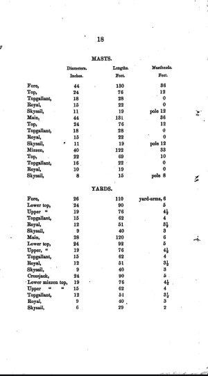
@Norgale the piece at the outer tip of the bowsprit through which the jibboom passes and below which the martingale, also known as a dolphin striker mounts is called the cap. The mastheads are similar devices at the top of each mast. The lower mast lengths for all 4 masts include the lengths below deck. There are typically two mastheads: lower mast through which the topmasts mount and top masthead through which the royal masts pass. Doubling where there's briefly two sections of masts are also referred to as hounds. Rob can recommend a good book for these old fashioned nautical terms.
 
@Norgale
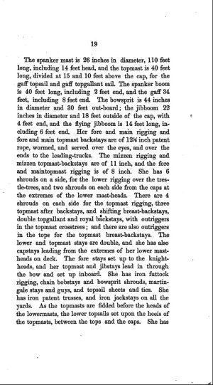
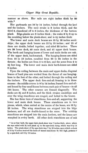
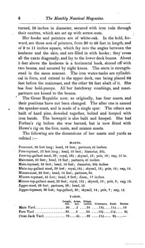
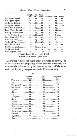
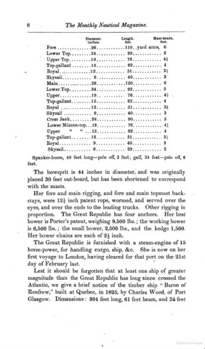
Thanks for the compliment. There's a couple well known pictures of Great Republic but they're after she had been relaunched as a three decked razee. To answer your concerns about accurate spar dimensions here's a specific list from McKay's shipyard as she was originally rigged (courtesy of Scott Bradner's well researched site). Bowsprit is 44" in diameter, 30' outboard from hull. In our Glory of the Seas research, we learned that each iron band was 3' apart, with 18" ends. That would mean 10 bands for 9 spaces equaling 27" and 18" into the hull and another 18" to outer cap for 30' total. The cap itself was 3 pieces each 6" for 18" in total. Two iron banded ends with a 6" inner piece. Inner jibboom would match 30' is 22" in diameter and extends 18' with a 4' end (add 4') Flying jibboom is 14' long including 6' end. Total for both outer jibboom and flying jib outside the cap is 36'. Counting the 30' inner that means this spar extends 67'6" including cap.

View attachment 523121
My question about this description was; When it says " the jibboom is 22 inches diameter and 18 feet outside the Cap with 4 feet end," what does "4 feet end mean"? Does it refere to 4 feet added to the jibboom or does 18 feet include the "4 foot end"?
 
My question about this description was; When it says " the jibboom is 22 inches diameter and 18 feet outside the Cap with 4 feet end," what does "4 feet end mean"? Does it refere to 4 feet added to the jibboom or does 18 feet include the "4 foot end"?
@Norgale since the description said with 4 feet end, I read that as "add 4 feet." When it comes to the 18 foot description it states the opposite: "including 6 foot end." In that case, I wouldn't add it since McLean clearly stated the 18 feet was inclusive of the 6 foot end.
 
So we have a 18 feet plus 4 feet jib boom and an 18 foot flying jib boom for a total of 40 feet passed the cap. That's nowhere near what the scaled drawings propose..
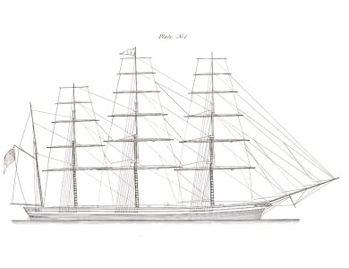
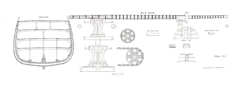
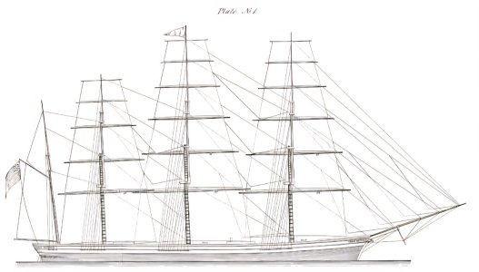
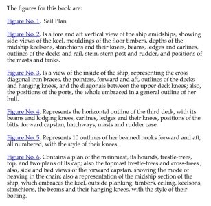
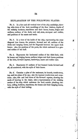
@Norgale, after you mentioned scaled drawings I took another look at the 6 original large fold-outs which accompanied the publication. Thanks to Scott Bradner's excellent research, we have access to the entire lengthy pdf article, as well as all 6 specially commissioned scale illustrations. Based on the sail plan, I agree with you. Ends in both cases apparently are added to basic dimensions, since the entire bowsprit, jibboom, flying jibbom combination appears to be about 90 feet. 30 foot inner, 18" cap, 18 foot outer jibboom, 4 foot end, 18 foot flying jibboom, 6 foot end totals 77 feet 6 inches. If the scale drawing is still longer (which looks like it's 90 feet or a little more) I would go with the drawing. To make it easier to calculate dimensions, I've enlarged plate no 1 by simply removing white space. Another detail to notice is the long slimming of the inner jibboom before it enters the monkey rail. Practically the entire upper section of the inner jibboom is gradually thinner down to allow it to match the monkey rail profile. Both inner jibboom and bowsprit are carved down to rectangles when entering the hull. This prevents rotation of either spar, which could be disastrous. Yet hardly any models include this important detail. I've included a brief description of all six plates. Another item I recognize is the large "lubber's hole" opening provided for in the main top structural illustration. From forward to almost entirely aft, there's a long oblong space on both sides of the top. We learned about this much larger space on Glory of the Seas..Again from a common sense practical application, this makes total sense as more than one sailor would be climbing through at the same time.

Screenshot_20250604_191137_Chrome.jpg

Screenshot_20250604_193548_Chrome.jpg

Screenshot_20250604_193613_Chrome.jpg

Screenshot_20250604_193655_Chrome.jpg

Screenshot_20250604_193714_Chrome.jpg

Screenshot_20250604_193733_Chrome.jpg

Screenshot_20250604_212133_Chrome.jpg

Screenshot_20250604_231839_Chrome.jpg
 
Last edited:
@Norgale
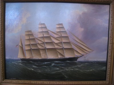
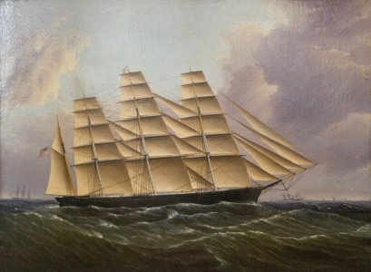
Here's two reproductions in Wikipedia of the same Great Republic painting by James E Buttersworth at the Old State House, Boston, MA. This depicts her original appearance as launched with all ordinary sails set. Note how her entire rig, including a long bowsprit precisely matches the no 1 sail plan illustration of her as published in the booklet which accompanied her launch.

'Clipper_Ship_Great_Republic'_by_James_Butterworth,_c._1853_-_Old_State_House_Museum,_Boston,...jpeg

James_E._Buttersworth_-_Great_Republic (2).jpg
 
Wow! You certainly do your research I'll say that. Thanks very much for being so generous with your pictures. There's a lot of info there which I will certainly study as I proceed with this project but getting back to the bowsprit and jib boom, your figures are almost the same as my estimates after measuring the drawing. I allowed 30 feet inside the cap and then divided the whole thing by the thirty feet and came up with 72 feet for the jib and flying jib combined outside the cap. After cutting a dowel to that length I laid it on the bowsprit to see what it looks like. Although it looks abnormally long it does appear to match the drawings and it does look to be in scale with the rest of the ship. I wanted to hear from you and maybe Rob, if he's paying attention, (HA) to see if you thought it looked ok.
Another thing is, do you think the 18" cap should be added to the length? It looks like it slips on over the end of the bowsprit and thereby becomes part of the 30 foot bowsprit length. As for thinning the base end of the jib boom, I think that would decrease the strength of the piece at a point where it should be at it's strongest. In any case I was trying to see how I could get that squared off end on the bowsprit and the jib without having to start with a huge dowel and grind the whole thing down to allow for the squared off part. It's amazing that you even noticed that. I would never have seen it if you hadn't pointed it out.

100_0007 - Copy.JPG

100_0006 - Copy.JPG
 
Last edited:
@Norgale
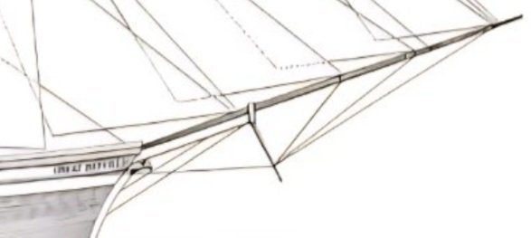
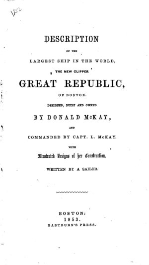
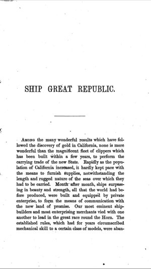
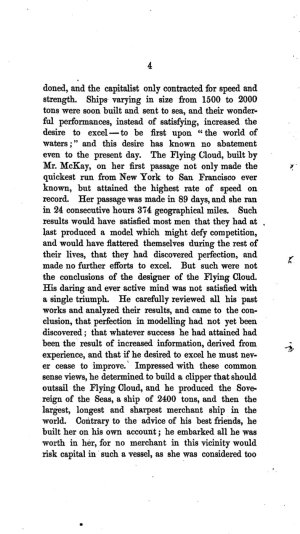
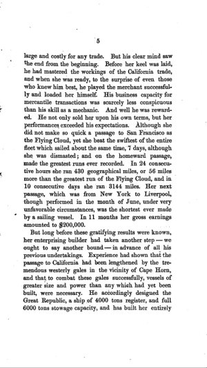
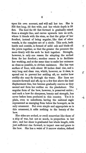
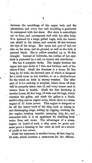
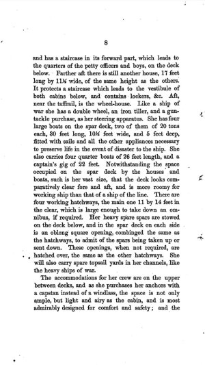
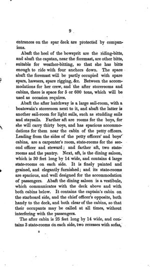
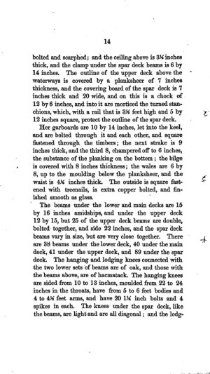
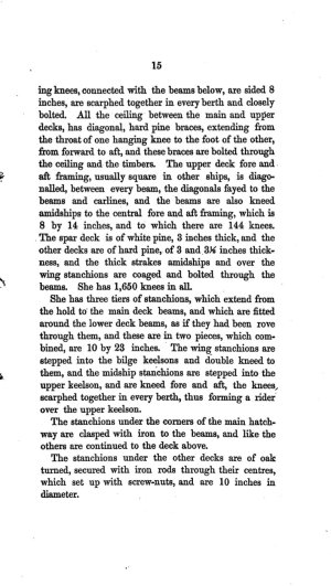
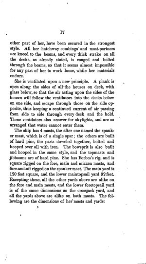
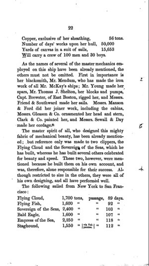
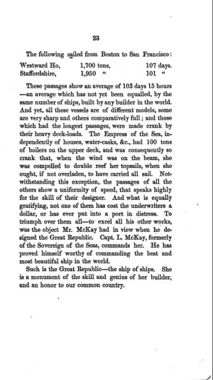
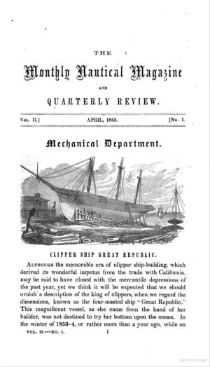
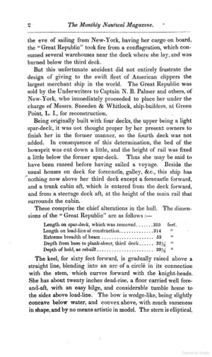
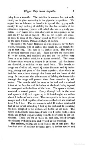
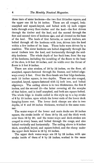
You're correct that the spar passes through the cap as a single piece. However McLean (a sailor himself) is quoting dimensions supplied to him from the McKay shipyard itself. They listed their specifics as before and after the cap. That adds the cap's dimensions to total combined length. As for thinning and squaring of these spars, I don't second guess historic photographic proof which we saw on Glory of the Seas. I've greatly enlarged the entire Great Republic bowsprit area. The bowsprit below clearly has parallel lines. Note how the inner jibboom thins down at an angle almost immediately behind the cap. It also gradually comes to a point as it gets further out. Incidentally since you're working so hard to realize the ship in her entirety, I've attached the full in-depth description of Great Republic published by Donald McKay himself at her launch.

Screenshot_20250605_122033_Chrome.jpg

Screenshot_20250605_124743_Chrome.jpg

Screenshot_20250605_124702_Chrome.jpg

Screenshot_20250605_124652_Chrome.jpg

Screenshot_20250605_124645_Chrome.jpg

Screenshot_20250605_124636_Chrome.jpg

Screenshot_20250605_124629_Chrome.jpg

Screenshot_20250605_124620_Chrome.jpg

Screenshot_20250605_124611_Chrome.jpg

Screenshot_20250605_124603_Chrome.jpg

Screenshot_20250605_124555_Chrome.jpg

Screenshot_20250605_124546_Chrome.jpg

Screenshot_20250605_124536_Chrome.jpg

Screenshot_20250605_124526_Chrome.jpg

Screenshot_20250605_124517_Chrome.jpg

Screenshot_20250605_124508_Chrome.jpg

Screenshot_20250605_124449_Chrome.jpg

Screenshot_20250605_124440_Chrome.jpg

Screenshot_20250605_124420_Chrome.jpg

Screenshot_20250605_124410_Chrome.jpg

Screenshot_20250605_124359_Chrome.jpg

Screenshot_20250605_124345_Chrome.jpg

Screenshot_20250605_124333_Chrome.jpg

Screenshot_20250605_124324_Chrome.jpg

Screenshot_20250605_124309_Chrome.jpg
 
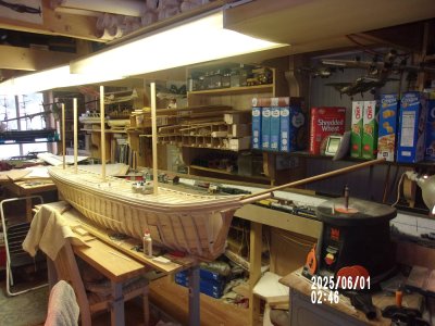
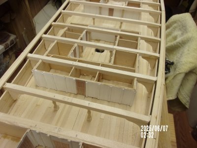
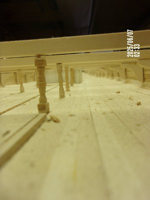
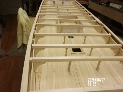
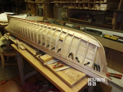
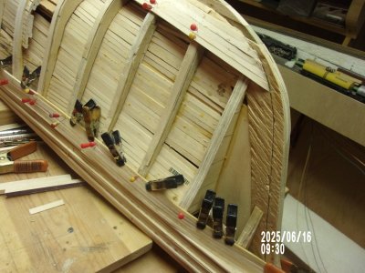
Finished the knees and turned stanchions on the second deck and now comes the framing for the hatches and other openings that are peculiar to the top deck.I see on my plans and the plans provided by ClipperFan that the weather deck has a lot of bracing and knees in it's construction that are not present on the lower decks. Not sure I'll do it all but at least some of the major ones should be installed. After that the cross beams will have to get some sanding to form the curvature of the top deck and then comes the deck and it's furniture. Lots to do on the top deck so I can see another year for this project and probably two more years before any kind of a finish. Oops! Forgot about the hull planking too. Sorry about the sideways pictures. I though I could straighten them out but I don't see how.

100_0020 - Copy.JPG

100_0021 - Copy.JPG

100_0022 - Copy.JPG

100_0023 - Copy.JPG

100_0019 - Copy.JPG

100_0018 - Copy.JPG
 
Sorry about the sideways pictures. I though I could straighten them out but I don't see how.
At the end at the left side of your post you find the ‘Attachment editor’, Pete. I have turned the pictures in question. Don’t know if that is only in my view of saved on the server for everyone.
And of course: you made some nice steps in the build. Impressive!
Regards, Peter
 
That's great Peter. Thanks for doing that. I checked the "Editor" and I see now, how to turn the picture. It used to be right on the picture in my Windows XP. I wish they wouldn't change everything so often. I always try to imagine being right there in my pictures. It's amazing how much room there is on that deck and the three below it are bigger yet. That's a whole lot of freight I think.
 
Finished the knees and turned stanchions on the second deck and now comes the framing for the hatches and other openings that are peculiar to the top deck.I see on my plans and the plans provided by ClipperFan that the weather deck has a lot of bracing and knees in it's construction that are not present on the lower decks. Not sure I'll do it all but at least some of the major ones should be installed. After that the cross beams will have to get some sanding to form the curvature of the top deck and then comes the deck and it's furniture. Lots to do on the top deck so I can see another year for this project and probably two more years before any kind of a finish. Oops! Forgot about the hull planking too. Sorry about the sideways pictures. I though I could straighten them out but I don't see how.

View attachment 524224

View attachment 524225

View attachment 524226

View attachment 524227

View attachment 524228

View attachment 524229
@Norgale,
Scenes of your internal structural build appear like looking inside a real ship. Simply amazing. I personally don't know of any other Great Republic build which replicates her entire insides like you're doing. Which is why it pains me to point this out. I know you've already announced that you're planning to abandon any effort to achieve a historically correct curvilinear stern on your massive replica. My personal feeling is that's a big mistake. On a much smaller model, say 1:700th scale like Callen Clark works in, such a glaring error can be overlooked. Not on the scale you're working in. If you don't fix it, your inaccurate replica will be forever marred. I know you don't want to read this but when it comes to your obvious love for this particular subject I strongly feel like this issue needs to be addressed. Rob and Vlad both faced a similar error when we discovered that both of their forecastle bulkhead heights were too low. They both courageously stopped their progress to immediately tear down and rebuild their entire forecastles. In fact, in Vlad's case he ended up removing all deck structures to refloor his entire ship. At 1:72nd scale that was an incredibly challenging project to take on. As old Jock Willis, owner of the Scottish tea clipper Cutty Sark proudly said "Where there's a will, there's a way." In fact that motto is emblazoned on the ribbon which surrounds the star on the stern of his proudest achievement. I'm positive that @rwiederrich and other veteran modelers would be more than willing to lend their expertise in helping you get a correct curvilinear stern on your impressive ship build. You just have to ask.
 
Somebody once said that "Great minds think alike" so I agree with you 100%. I have already decided to do something about the stern but just haven't decided what. I've been working on the bow for the last several weeks and haven't got back to the stern yet. However I WILL do something about the curve and I thank you for mentioning it to me. It shows that your as concerned about it as much as I am and I appreciate that very much. With your knowledge and Rob's I hope you both won't hesitate to mention anything else that is bothering you. It's the best way to keep this project looking good. Meantime, working on the bow, it looks like the upward curve of the sheer line is too sharp at the bow. I think the curve should be more gradual but I don't know just what to do about it at this point. Please let me know what your think.
 
@Norgale,
Scenes of your internal structural build appear like looking inside a real ship. Simply amazing. I personally don't know of any other Great Republic build which replicates her entire insides like you're doing. Which is why it pains me to point this out. I know you've already announced that you're planning to abandon any effort to achieve a historically correct curvilinear stern on your massive replica. My personal feeling is that's a big mistake. On a much smaller model, say 1:700th scale like Callen Clark works in, such a glaring error can be overlooked. Not on the scale you're working in. If you don't fix it, your inaccurate replica will be forever marred. I know you don't want to read this but when it comes to your obvious love for this particular subject I strongly feel like this issue needs to be addressed. Rob and Vlad both faced a similar error when we discovered that both of their forecastle bulkhead heights were too low. They both courageously stopped their progress to immediately tear down and rebuild their entire forecastles. In fact, in Vlad's case he ended up removing all deck structures to refloor his entire ship. At 1:72nd scale that was an incredibly challenging project to take on. As old Jock Willis, owner of the Scottish tea clipper Cutty Sark proudly said "Where there's a will, there's a way." In fact that motto is emblazoned on the ribbon which surrounds the star on the stern of his proudest achievement. I'm positive that @rwiederrich and other veteran modelers would be more than willing to lend their expertise in helping you get a correct curvilinear stern on your impressive ship build. You just have to ask.

Somebody once said that "Great minds think alike" so I agree with you 100%. I have already decided to do something about the stern but just haven't decided what. I've been working on the bow for the last several weeks and haven't got back to the stern yet. However I WILL do something about the curve and I thank you for mentioning it to me. It shows that your as concerned about it as much as I am and I appreciate that very much. With your knowledge and Rob's I hope you both won't hesitate to mention anything else that is bothering you. It's the best way to keep this I am project looking good. Meantime, working on the bow, it looks like the upward curve of the sheer line is too sharp at the bow. I think the curve should be more gradual but I don't know just what to do about it at this point. Please let me know what your think.
@Norgale
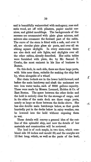
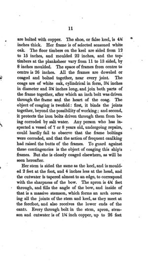
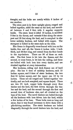
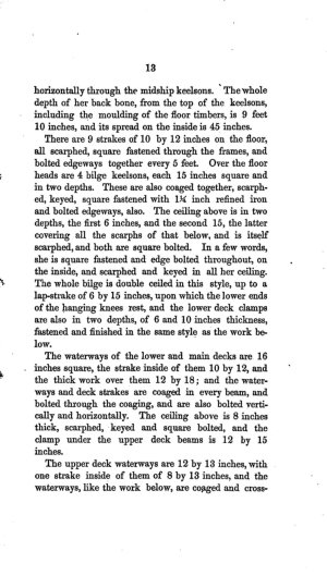
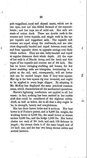
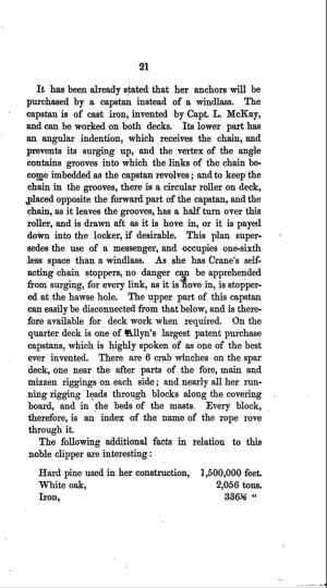
I am relieved and thrilled to learn that you intend to pursue the semi elliptical stern that Donald McKay designed for his largest ever merchant vessel. As for her tricky keel, you're right. Similar to his clipper  Lightning her keel isn't at all angular it's an arc of a circle. I've attached an excerpt of the keel description from the pamphlet. In addition there's details of the 60' curving keel and the semi elliptical stern. Actually, your absolute best resource is that very lengthy description. It's penned by McKay's friend, fellow Scottsman and previous sailor Duncan McLean.
Screenshot_20250608_134611_Chrome.jpg

Screenshot_20250608_140513_Gallery.jpg

Screenshot_20250608_141014_Gallery.jpg

Screenshot_20250608_141901_Gallery.jpg
 
Back
Top