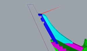
Yes, Dave. It is one of the parts for the wing transom.Jim: I agree about CNC! Is that part the wing transom?
-

Win a Free Custom Engraved Brass Coin!!!
As a way to introduce our brass coins to the community, we will raffle off a free coin during the month of August. Follow link ABOVE for instructions for entering.
-

PRE-ORDER SHIPS IN SCALE TODAY!
The beloved Ships in Scale Magazine is back and charting a new course for 2026!
Discover new skills, new techniques, and new inspirations in every issue.
NOTE THAT OUR FIRST ISSUE WILL BE JAN/FEB 2026
- Home
- Forums
- Ships of Scale Group Builds and Projects
- HMS Alert 1777 1:48 PoF Group Build
- HMS Alert 1777 1:48 Group Build Logs
You are using an out of date browser. It may not display this or other websites correctly.
You should upgrade or use an alternative browser.
You should upgrade or use an alternative browser.
- Joined
- Sep 9, 2017
- Messages
- 135
- Points
- 133

Many thanks,Jim...Yeah I did that... the issue arises when I "dry fitted"the wing transom /stern post assembly into the cradle.Anyway I shall continue now that I have seen your photos. Thanks again, DanHello Dan! Thank you for the compliments!!! This build log is not just to show the build process and skills, it is to help others who might have questions when came across and stumble. There is no such thing as 'intruding' in my log. I am learning along with you, and if I can be on help, that would be the best honor for me! Please submit questions you may come across!! Please do so!!
Now, back to your question. Yes this part a bit tricky, First of all, use the self-adhesive template and affix to the part. one is going on one side, another the opposite side of BL30. You will have to grind (shape) both sides of the part shaded area.
View attachment 176956
View attachment 176957
Once you shape it, test the fit to the inner post (Part BL19), if necessary open a bit scarphs in the BL30 and BL19). This has to be done on a fit & try, as many times until it fits perfectly. Also, pay attention, the part BL30 has to angeled to the sternpost
View attachment 176958
View attachment 176959
View attachment 176960
View attachment 176961
View attachment 176963
Pay attention for 4 notches, they should be facing the back.
View attachment 176974
Let me know if this helps.
- Joined
- Apr 1, 2019
- Messages
- 478
- Points
- 373

Alert is only our entry-level kit, and the kit being designed will have a much higher reduction degree.Perhaps the next challenge for the new generation of model ship kits companies like Trident and CAFModel is to delivery to its customers timber joinery like on the original ships.View attachment 176692View attachment 176693View attachment 176694
Hello @Jimsky ,
since you seem to be "farest" with this build I thought I'd ask you:
Part BL19 (inner stern post?) has a little "step" on it's upper end, clearly seen in your last picture in Post 87 .
Well, when I started to check and clean the pieces I noticed that it won't fit into the template because of that step. I thought of a "production error", but since you show the same "step" I am not sure if the "error" is on BL19 or the template ... In the picture of the Instruction this upper part seems to be without this step (if you compare the hight seen from the side), but I am not sure now if I should cut it off .. it might be needed "later" for positioning/alignment of the transom?
I hope you - or someone else here - could enlighten me on this "dilema"!
Did your incisions on BL10/BL11 meet the template? ...I will have to "clean" them quite intensive ...
since you seem to be "farest" with this build I thought I'd ask you:
Part BL19 (inner stern post?) has a little "step" on it's upper end, clearly seen in your last picture in Post 87 .
Well, when I started to check and clean the pieces I noticed that it won't fit into the template because of that step. I thought of a "production error", but since you show the same "step" I am not sure if the "error" is on BL19 or the template ... In the picture of the Instruction this upper part seems to be without this step (if you compare the hight seen from the side), but I am not sure now if I should cut it off .. it might be needed "later" for positioning/alignment of the transom?
I hope you - or someone else here
Did your incisions on BL10/BL11 meet the template? ...I will have to "clean" them quite intensive ...
Just a pure guess as I don't have the kit yet: Could be that the starboard side should face down? (assuming that the template is not as thick as the parts)
Markus and Poul. My kit also has the part BL19 with an extra notch, which appeared as functional by design. Although, I have not found any connections with this part for the future use I made a decision towards leaving it untouched.
Also, I found that part also left untouched on the build of one of the Chinese member LanHai
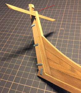
@Trident Model Can you please clarify if the part BL19 required the notch (on the top) will need for future use?
Also, I found that part also left untouched on the build of one of the Chinese member LanHai

@Trident Model Can you please clarify if the part BL19 required the notch (on the top) will need for future use?
- Joined
- Apr 1, 2019
- Messages
- 478
- Points
- 373

Sorry, the reply is very slow these days. The position marked by the red arrow can be removed at this stage. This is only a temporary local structure strengthening design. I'm sorry to miss this link in the manual.
Great!! Thank you for the prompt response, Trident Model!
- Joined
- Apr 1, 2019
- Messages
- 478
- Points
- 373

I'm sorry, my English is not very good.
- Joined
- Apr 1, 2019
- Messages
- 478
- Points
- 373

That's a relief, as I removed mine when I didn't see it on the instructions!The location of the arrow is very fragile and easy to break when installing. All local structures have been strengthened and can be polished off after being fixed with glue.
Hi Jimsky, I need your opinion on part AL4.
For parts AL1 - AL3 there is stickers provided to help with the shaping and for parts AL5, etc there is the MDF cutouts provided for shaping, but I just can't finding anything that will assist with shaping of AL4.
On the development page for the Alert I came across this photo that clearly illustrates that there should be a sticker for AL4.
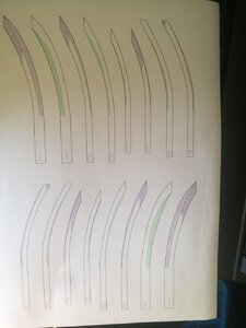
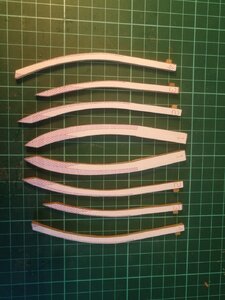
Am I missing something?
For parts AL1 - AL3 there is stickers provided to help with the shaping and for parts AL5, etc there is the MDF cutouts provided for shaping, but I just can't finding anything that will assist with shaping of AL4.
On the development page for the Alert I came across this photo that clearly illustrates that there should be a sticker for AL4.


Am I missing something?
Hello Roger, No, you are not missing anything. I could find neither the corresponding MDF template nor the sticker for Frame #4. Let's ask Trident.
@Trident Model, Can you help us with Frame #4? We cannot find the template for proper shaping. Can you attach the template as .pdf and we will print out?
@Trident Model, Can you help us with Frame #4? We cannot find the template for proper shaping. Can you attach the template as .pdf and we will print out?
- Joined
- Apr 1, 2019
- Messages
- 478
- Points
- 373

No template is needed for No.4 rib. The amount of grinding for this rib is very small, only the lower part of the rib needs to be polished very little.
Alright, folks! All hands on deck! At first, I'd like to spend a moment to thank all of you for the interest, comments, and 'likes'.  It does encourage me to continue. So let's continue...
Since I have discussed and shown the photos of the shaping\installing wind transom (Part BL30) when answering Dan's @danielw no need rewrite, just check the post #97
However, to finish with this part of the assembly and move to the next chapter, below is the photos when the wind transom installed.
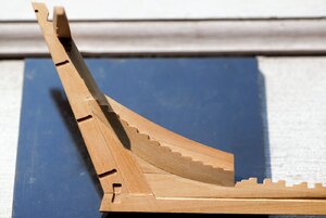
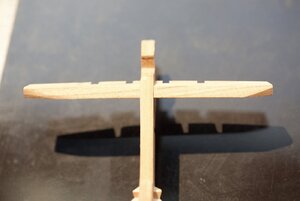
Please pay attention to the next photos. The part BL-19 require some trimming, circled red (arrow pointed), must be removed before assembly\glue. This was technological while CNC cut process, and doesn't play any roles in the actual build. It has to be flush with the cut (photos below).
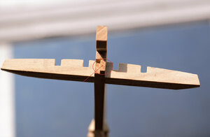
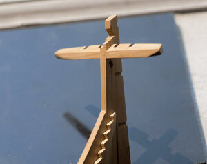
Another view


Here is how the entire assembly looks in the building jig.
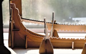
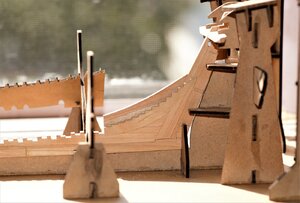
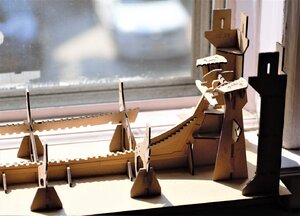
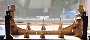
Well, I can simply declare the first assembly part as - completed. We have built the Berth or building jig, everything fits well. We assembled the keel part gluing together multiple components. We utilized the templates designed and provided in the kit to make assembly presision and easy for novicess. Also, we use paper stickers to shape (grind) some parts. They are (templates) a proven vinner!! I have enjoied every day while building...
In the next chapter, we will assemble the frames (ribs). This is where the real fun should start. Until then, thanks you for the interest. To be continued...
Since I have discussed and shown the photos of the shaping\installing wind transom (Part BL30) when answering Dan's @danielw no need rewrite, just check the post #97
The Naval Cutter ALERT- 1777, POF by Jimsky
Many thanks, @Norway Knut, @JohnA John and all for the compliments and likes! :) Continue with the false keel assembly, and today we actually moving to 'Apron' (or false post). It is consists of two parts: the upper section part BL7 and lover section part BL8. To complete this assembly we will...
shipsofscale.com
However, to finish with this part of the assembly and move to the next chapter, below is the photos when the wind transom installed.


Please pay attention to the next photos. The part BL-19 require some trimming, circled red (arrow pointed), must be removed before assembly\glue. This was technological while CNC cut process, and doesn't play any roles in the actual build. It has to be flush with the cut (photos below).


Another view


Here is how the entire assembly looks in the building jig.


Well, I can simply declare the first assembly part as - completed. We have built the Berth or building jig, everything fits well. We assembled the keel part gluing together multiple components. We utilized the templates designed and provided in the kit to make assembly presision and easy for novicess. Also, we use paper stickers to shape (grind) some parts. They are (templates) a proven vinner!! I have enjoied every day while building...
In the next chapter, we will assemble the frames (ribs). This is where the real fun should start. Until then, thanks you for the interest. To be continued...
Jimsky, Before you shape parts 2 & 3 fit & glue 1 & 4 as they are holders for 2&3, don't pre shape & pay attention to where the shapin line ends near the top as this is very important for rib alignment with the keel! ( I'm guessing they get cut off at this point later as the Ribs are glued to the Berth at the top.
Its easier to remove lower 2 & 3 shaping to fit rather than too much at the start.
Its easier to remove lower 2 & 3 shaping to fit rather than too much at the start.
Many thanks, Paul! I will definitely take your suggestion into account.Jimsky, Before you shape parts 2 & 3 fit & glue 1 & 4 as they are holders for 2&3, don't pre shape & pay attention to where the shapin line ends near the top as this is very important for rib alignment with the keel! ( I'm guessing they get cut off at this point later as the Ribs are glued to the Berth at the top.
Its easier to remove lower 2 & 3 shaping to fit rather than too much at the start.
Chapter 2: Frames
Well..., with anticipations to start, we are moving to the next chapter of our build log - assemble the Frames or Ribs how they described in the instruction manual. if you recall, the kit's manual suggested assembling the frames before the berth. However, as most of us, who are building this Alert kit, we build the berth first, and this is no error. Both are two independent processes and can be started in any order. IMHO, as the first time POF builder, I feel a bit comfortable building the berth, first. Anyway, let's move on.
I think, it worth to mention\learn some nautical terminology related to the frame construction as we will use them quite often in this building log. Below are images from the book by Peter Goodwin - The Naval Cutter Alert 1777 ( areally nice companion to our kit build). Take a look at what parts the frames are consists.
* Please note: the images are for educational purposes. The first image is the disposition of the midship timbers. It is isometric and gives a great idea of how the frames were laid. Be familiar with the terminology. It is a nice way to learn, IMHO
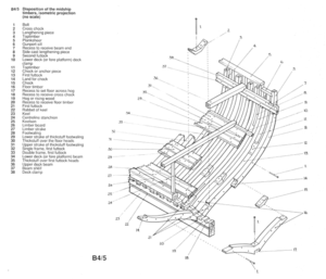
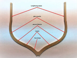
The second image is showing frames construction. Take a close look (both B4/6 and B4/7), each of those showed two types of frames (you will find when assembling frames in our kit). The first frame (top) B4/6 attached to the rising wood using both: 'cross chock' and 'first futtock', where 'first futtock' are two pieces (left and right). Both futtocks attached to 'cross chock' using bolts. However, the second frame (below image) attached to the rising wood using 'floor timber'. Pretty interesting ...ha? Get confused yet??? Both: 'first futtock' and 'second futtock' connected using the 'chock' (or anchor piece). There should be only one 'chock' connection (left and right side on the frame). The last piece of the frame is the 'lengthening piece', it is always connected with 'second futtock' using 'plain scarph'.
The reason I want you to be familiar with the frames disposition is in the kit, we will have to assemble the frames the same way. Pretty cool...I am very excited.
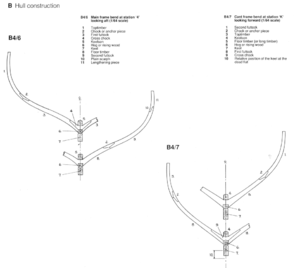
Words to be familiar with. Check both images on top.
Example of the single frame and paper templates. Actually, this is the frame AL1 (the first one)
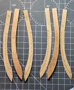
This is the frame AL1 shaped according to templates and shaded area
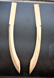
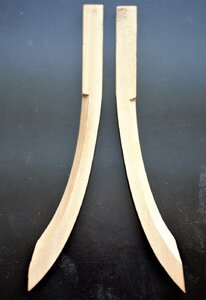
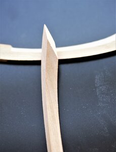
Some other single frames (Type 1)
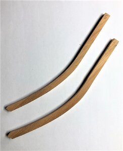
Type 2, consists of 2 pieces joined by 'plain scarph'
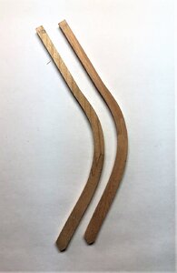
Type 3. Parts are joined using 'chock or anchor piece.

'chock' joints, we will use them a lot down the road...
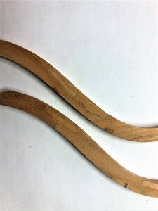
Type 4 and 5 frames. The majority of the frames will be of those styles. Two of those types tightened together with bolts will make a double-frame. Alet has 10 double-frames. Will talk about those later...
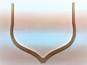
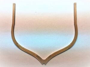
Breakdown pieces by their names.
to be continued... stay tuned.
Well..., with anticipations to start, we are moving to the next chapter of our build log - assemble the Frames or Ribs how they described in the instruction manual. if you recall, the kit's manual suggested assembling the frames before the berth. However, as most of us, who are building this Alert kit, we build the berth first, and this is no error. Both are two independent processes and can be started in any order. IMHO, as the first time POF builder, I feel a bit comfortable building the berth, first. Anyway, let's move on.
I think, it worth to mention\learn some nautical terminology related to the frame construction as we will use them quite often in this building log. Below are images from the book by Peter Goodwin - The Naval Cutter Alert 1777 ( areally nice companion to our kit build). Take a look at what parts the frames are consists.
* Please note: the images are for educational purposes. The first image is the disposition of the midship timbers. It is isometric and gives a great idea of how the frames were laid. Be familiar with the terminology. It is a nice way to learn, IMHO

The second image is showing frames construction. Take a close look (both B4/6 and B4/7), each of those showed two types of frames (you will find when assembling frames in our kit). The first frame (top) B4/6 attached to the rising wood using both: 'cross chock' and 'first futtock', where 'first futtock' are two pieces (left and right). Both futtocks attached to 'cross chock' using bolts. However, the second frame (below image) attached to the rising wood using 'floor timber'. Pretty interesting ...ha? Get confused yet??? Both: 'first futtock' and 'second futtock' connected using the 'chock' (or anchor piece). There should be only one 'chock' connection (left and right side on the frame). The last piece of the frame is the 'lengthening piece', it is always connected with 'second futtock' using 'plain scarph'.
The reason I want you to be familiar with the frames disposition is in the kit, we will have to assemble the frames the same way. Pretty cool...I am very excited.

Words to be familiar with. Check both images on top.
- Toptimber (top part of the frame)
- Chock or anchor piece (joined futtocks)
- First futtock\Second futtock (parts of the frame)
- Cross chock (attached to rising wood)
- Floor timber (attached to rising wood)
- Plain scarph (joined futtocks with lengthening piece)
- Lengthening piece
- Single frame (made from a single piece). They don't require any assembly. However, they need to be shaped using paper\MDF board templates. The frames are AL-1 to AL6.
- Type 2 frames consist of 2 pieces. They will be assembled using the 'plain scarph' joint. Template jigs made from MDF and labeled for each frame. Some of them will also require shaping (bevel), and for those types of frames, you will use the same jig. The laser-cut will give you an indication of the beveled line.
- Type 3 frames consist of three pieces. they will be assembled using the 'chock'. Some of them required beveling as well. Check the MDF template to identify the number corresponding to the frame.
- Type 4 and Type 5 consists of 7 pieces. Connection made using 'chocks' between 'futtocks' and 'plain scarphs' between 'futtocks and 'lengthening pieces'. The difference between type 4 and type 5 how they will be attached to the rising wood. Type 4 will use 'floor timber' and type 5 will use 'cross chock'.
Example of the single frame and paper templates. Actually, this is the frame AL1 (the first one)

This is the frame AL1 shaped according to templates and shaded area


Some other single frames (Type 1)

Type 2, consists of 2 pieces joined by 'plain scarph'

Type 3. Parts are joined using 'chock or anchor piece.

'chock' joints, we will use them a lot down the road...

Type 4 and 5 frames. The majority of the frames will be of those styles. Two of those types tightened together with bolts will make a double-frame. Alet has 10 double-frames. Will talk about those later...


Breakdown pieces by their names.

to be continued... stay tuned.
Jimsky, A wonderful tutorial... Well done .
Danielw
Yep, Your build log will be a big help for a lot of us I'd say...
You're not only showing Your build progress but really go into detail of how to prepare/assemble the parts. I like that!
Keep going


