The Naval Cutter ALERT- 1777, POF by Jimsky

I’ve completed most of the frames and Im just waiting for the replacement keel parts which Trident says he is sending by EMS (The original boards were two very different colors). Your log will be invaluable when I start The keel assembly.

Have a couple of questions:

I want to be able to show the interior details; cabin, ladders, stove, etc. I was thinking of cutting away some of the frames on one side after the hull has been removed from the jig. Either cutting every other frame or cutting away many frames mid-ships. Any ideas on that?

I don’t want to cut away deck frames since I plan to mount and rig all the cannon.I may remove one or more of the hatches.

Trident included the parts for the cabins (don’t know if they include the sail room) and they look pretty good. But, he did not include any drawings or instructions for them. Do you know when they might be coming?

Thanks
There are many examples of cut-away hulls on the internet.
Some look like the ship is in the middle of repairs
and others have clean cut-outs like Occre's Bounty kit
Just be sure to find a way to support the cut frames and maintain them straight or at least parallel to the other full frames.
 
I’ve completed most of the frames and Im just waiting for the replacement keel parts which Trident says he is sending by EMS (The original boards were two very different colors). Your log will be invaluable when I start The keel assembly.

Have a couple of questions:

I want to be able to show the interior details; cabin, ladders, stove, etc. I was thinking of cutting away some of the frames on one side after the hull has been removed from the jig. Either cutting every other frame or cutting away many frames mid-ships. Any ideas on that?

I don’t want to cut away deck frames since I plan to mount and rig all the cannon.I may remove one or more of the hatches.

Trident included the parts for the cabins (don’t know if they include the sail room) and they look pretty good. But, he did not include any drawings or instructions for them. Do you know when they might be coming?
Hello Submarinerblue!
I am glad the build log will come handy while assembling a keel. Also, check Paul's @paulv1958 build log. He has videos assembling the keel (Very good, just what doc prescribed...)

I am not an expert suggesting to cut frames to expose the interior. I wouldn't definitely cut every-other frame. In fact, I wouldn't cut any frame... but this just me. Maybe others can chime in.

You don't have to cut the deck frames to show 'inside', you can lay only desk planks under the gun carriges and leave the entire deck unplanked (naked). Actually this is a great way to show the beams, carlings (the deck structure)

We will utilize the pictures from Chineese build for the underdeck structure. We have some 3D and built model images. I don't think there will be an aditional manual for that. Also, a great build companion the book of P,Goodwin -The Naval Cutter Alert 1777. It does show some accomodation compartment details :)
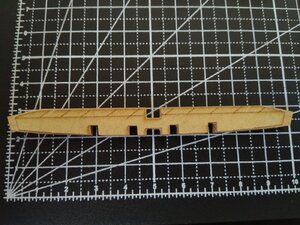
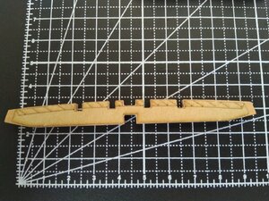
Here‘s what I had in mind. The photos are from The Colonial Schooner by Harold Hahn. It appears that he cut through parts of frames after the hull had been completed and strengthened with partial deck and hull planking.

There are over 50 parts for the cabins. Trident must have had a plan in order to laser cut all of them. I don’t see how we can assemble them without that plan. The Godwinson book can help but can’t substitute for a plan from Trident.

BA6282D5-5420-4CF8-B77F-F03B6DD0C1EE.jpeg5DA9F725-2F52-4557-AEAF-90158765FE4C.jpegA10A7A2F-0F60-4FC2-8A8F-A7FF1994FB03.jpeg6FB67093-3252-435D-AC62-655BE9EAB217.jpegD9B97B2D-9A6D-475A-819E-36F675E6E84B.jpeg
 
Hello Jimsky,
please let me come back to you with another question:

The Wing Transom needs some work and your pictures in Post 115 did it make a lot clearer ... but what about the Ends? The cut out part BL30 is a good 2 to 3mm longer on both sides than the template attached to it.. did you cut/sand it to meet the template? Is the template the "real" final shape or are just the beveling lines interesting to form the transom correctly?
IMG_20200926_134133.jpgIMG_20200926_134038.jpg

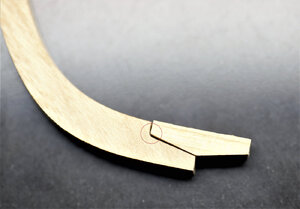
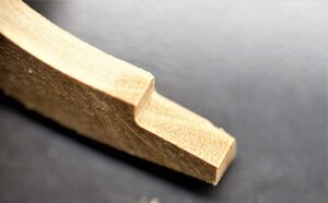
Also this little "spike" at the end of the to bevel part in the second picture bothers me a little .... if anyone got a picture in the "working-state" on that part I'd be very thankful! I am afraid the little 3D-Creator in my brain is on vacation when I look at that part ;)
 
Hello Jimsky,
please let me come back to you with another question:

The Wing Transom needs some work and your pictures in Post 115 did it make a lot clearer ... but what about the Ends? The cut out part BL30 is a good 2 to 3mm longer on both sides than the template attached to it.. did you cut/sand it to meet the template? Is the template the "real" final shape or are just the beveling lines interesting to form the transom correctly?
Hello Markus, not sure how much you can trust my expertise, but i will try to explain the way I make this part in my build. Take a look at this post:


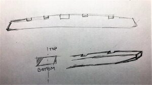
So...the paper template is the correct size of this part. However, leave both ends about 1mm from each side for final adjustments. The template affixed both sides. The shaded area has to be sanded out. Mark the virtual line from the top of the shaded line to the edge of the bottom and shape one side (check my sketch). Then turn upside, and shape another side the same way: from the start of the shaded line to the bottom edge of the opposite side.

IMG_1651.jpeg
 
Don't take the ends off part 31 as part 37 sits on each end. If it appears to be too long after everything is added it can be sanded back later when you take the hull out of the holder. It can be deceptive and parts 37 only just fit on it without adjusting length.

I t wil become obvious when you add all the other parts for the stern.

Use the shading a guide only. As stated in the manual only go to approx 70% of the sanding and adjust as needed to fit. Look at the area on the berth it fits into its curved like an aeroplane wing on the back side and tilted on the front to take the ribs. The tilt is similar to the angle of the keel.
 
Yep, Your build log will be a big help for a lot of us I'd say...
You're not only showing Your build progress but really go into detail of how to prepare/assemble the parts. I like that!
Keep going
Since Jimsky is focusing on the Alert I thought that I would drop in to watch the fun keeping him away from a smaller and less complicated canoe. Hope the group doesn't mind an interested sideliner. Always something to see and learn. PT-2
 
Since Jimsky is focusing on the Alert I thought that I would drop in to watch the fun keeping him away from a smaller and less complicated canoe. Hope the group doesn't mind an interested sideliner. Always something to see and learn. PT-2
You are more than welcome, PT-2! The group will be happy to anyone showing interest. Hope you will gain enough interest and will order your Alert kit! Cannot explain how much fun it is!
 
Much appreciated with all your comments and likes, folks. I didn't expect the log would be much of interest and really happy that it can be helpful for others. :)

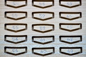
Buy now we should be familiar with the basic frames structure, and we are ready to assemble some frames. So...what should we start from? Yea, I hope you said removing the frame's parts from the timber board and sort them out. Personally, I think this is one of the important tasks, and you shouldn't underestimate its value. For example, you can 'nock' the corners (most typical), you can cut the piece of the part instead, or you can 'chip' the part, and this can happen specifically at the joint. :( We should avoid it at any cost.

Working thru my build, I thought it would be nice to show my method of removing parts from the frets (timber board). I made small videos, just enough to understand the process. I am no claiming that this is the best or the only way, I am sure others do differently. This is the way I found working the best for me and hope it might be adapted for your build.


Here are my rules when removing parts:
- always cut the part from the outer edge. You will have a chance to clean thereafter (my second video)
- try, where possible to move the scalpel away from the part. This will avoid 'nock' the parts if the scalpel slipped
- if cutting material to thick to cut once, use a scalpel to outline the cut a few times before plunging the scalpel for the actual cut.
- Carefully cut near the corners, joints, and end pieces. These are the most important

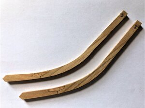
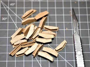
I choose to cut the frame's parts by 'chock's', Hmm...familiar terminology...I simply label all the chocks part numbers and start with the batch of ten. For example, let choose frame # 8. This frame is one of the 'cant' frames (new term). Those types of frames seen at the Stem (bow) and Stern sections. They will be installed on the rising wood. In our kit parts are BL33 and BL34. Back to cant frame #8 (photo below). I have already assembled it, but just to get an idea.

IMG_1657.jpeg

This is Type 3 frames (according to the Trident manual) It has three pieces: floor timber, second futtock both joined by chock (or anchor piece). In our case, this translated as the 'second futtock '- part AL8-1, 'chock' -part 8-2, and 'floor timber' - part AL8-3. Now, we will find all of the parts we need and cut them out from the timber board. In the same way, I will identify and remove parts from frets by a batch of 10, using chock as the guide.

600_0803.jpg

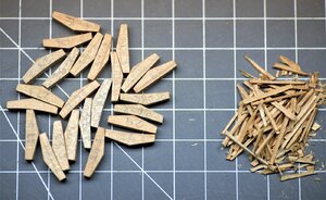
Chocks are removed and ready to clean up.
600_0791.jpg

Check this out, there are two types of 'chocks'. Those are for different types of frames. Do not modify their shapes
600_0792.jpg
The cleaning process described in the below video. Please pay attention to how I move the scalpel, The 'chock' is one of the most important elements in the frame. You DO NOT WANT to change the size and shape of 'chocks' at any cost.


This is actually described in the instruction manual on page #2. Excessive polishing can cause a big gap between components and parts, affect the whole strength of the frame. If you sand extra, you will have the gaps in the joints. This will weaken the frame, but most importantly, it will change the geometry (shape) of the frame. This is why it is important to carefully clean up.

600_0795.jpg

to be continued...
 
continue at where we left...

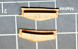
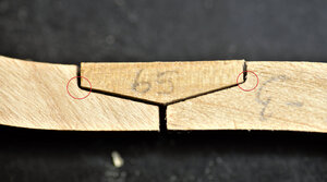
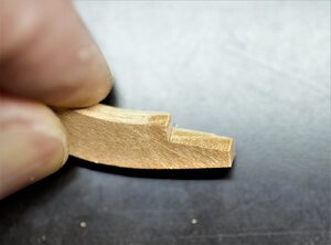
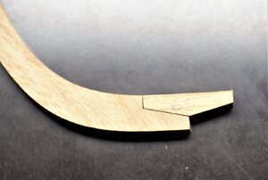
The beauty of CNS parts is you don't have to remove char. Often time, when removing char, you can accidentally change the shape of the parts. With CNC the shape of the part is not touched, nice and sharp. One of the challenges waiting for you is the scarphs. Take a look below photos. Circled red is the problem scarph, why? I hope you said it is not as sharp as the 'chocks' end. If you do say so, you awarded a trophy. :) This is due to CNC machining and we have to correct this.

600_0831_edited.jpg

600_0839_edited.jpg

600_0833.jpg

Correcting this will require some training. Take a look at my second video (almost et the end), I use a hobby knife, with a different blade type. You must control the blade pressure and the amount of wood removing. Take the least amount and check, repeat until fully satisfied. It should look similar, if not better, than on the photo below. ;)

600_0841.jpg

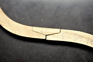
This is how joint looks after 'surgery' we described above
600_0850.jpg

So what happened if you don't clean the joint? It will look like the below photo (right side)
600_0851.jpg

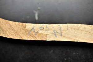
Note the letter 'N'. Because I work on each chock and scarf joint individually I crossed the chock\frame part so easily identify when gluing together. And the parts are not glued yet... Yea... a lot of work... but who said it will be easy? It is absolutely fun, folks! ..

600_0856.jpg

Other photos of various process
600_0788.jpg

600_0789.jpg
600_0800.jpg
before cleanup
600_0822.jpg
after clean up
600_0823.jpg

600_0824.jpg

600_0826.jpg

Some of my holding part timber thickens was quite thick... Almost a half mm.
600_0828.jpg


Bottom line: Don't rush, take your time, check the parts before cleaning. Change the new blade frequently or sharpen as necessary. If the blade becomes dull it can chip\splint the part (specifically on the corner joints). Most important have fun!!

to be continued...
 
Great work Jim... As an aside ,did you get any "panels" that didn't seem to be very well cut? By that I mean that the parts would not separate from the panel without much and I do mean much forceful cutting and when some did separate there were significant "furry "edges where the manufacturing cutter did not cut cleanly,
I've been through so many scalpel blades. BTW my processes for removal are identical to yours. I also noted that the "cut" by the machine did not seem to be absolutely verticle .Your pieces seem much cleaner even before your sanding away the surplus. Dunno .. I'm not having a whinge, it's just an observation. maybe it's just me...
 
Hello Daniel,
Thank you for your comments. Yes, I did have those timber panels with 'furry' edges. As you mentioned this is due to a dull cutter used. I consulted with Triden Models, and he confirmed that all parts are made with about 1.00 ~ 1.5mm more wood for sanding. All those 'wrinkles' can be easily sanded off. You can check the amount you can remove by inserting the part\s into the corresponding frame's template.
 
Back
Top