The Naval Cutter ALERT- 1777, POF by Jimsky

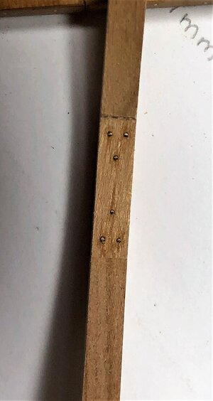
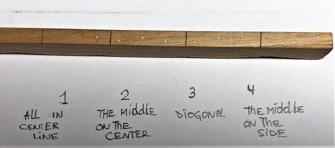
Greetings... All hands on deck. This is not a regular post update, it is rather a question. With all, your help I made a decision for'bolt' placement and chose the brass as the imitation material. The 'chock' will be bolted using a pattern from the AOTS book. As for the long 'plain scarphs,' i made some samples and want to find out your thoughts. I am debating between #2 or #4. Note: the scarph joints are not sized (as they should be), they only to separate and emphasize the overview. Your opinions and comments are more than welcome!

1. all bolts are in the centerline
2. the middle bolt in the centerline
3. all bolts are diagonal placement
4. The middle bolt on the side
IMG_1662.JPEG
 
Give your using wire beware of the tapering points for ribs 1-16 & 71-55 with 5-16 being the most significant across joints. Shape first or mark tapers then consider options?.
I don't know if maybe this could be an option?:
  1. Drill the assembled frame
  2. Shape the inside of the frame
  3. Clean the holes from the outside of the frame
  4. Shape the outside of the frame
  5. Clean the holes but from the inside, this time
  6. After final fairing, insert bolts (from both inside and outside in case real boltheads has been made )

    I think that way it would also be possible to use blackened bolts
 
Greetings... All hands on deck. This is not a regular post update, it is rather a question. With all, your help I made a decision for'bolt' placement and chose the brass as the imitation material. The 'chock' will be bolted using a pattern from the AOTS book. As for the long 'plain scarphs,' i made some samples and want to find out your thoughts. I am debating between #2 or #4. Note: the scarph joints are not sized (as they should be), they only to separate and emphasize the overview. Your opinions and comments are more than welcome!

1. all bolts are in the centerline
2. the middle bolt in the centerline
3. all bolts are diagonal placement
4. The middle bolt on the side

View attachment 182667

Hallo Jim,
if this pattern is for chocks, than you can not use only three bolts - you have to make minimum four bolts!
With three the bolt in the center would go directly through the joint of the two futtocks the chock is connecting!
Make six - than it would be correct, or four in a rectangle pattern
frames.jpg
 
Give your using wire beware of the tapering points for ribs 1-16 & 71-55 with 5-16 being the most significant across joints. Shape first or mark tapers then consider options?.
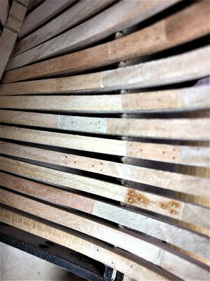
Many thanks, Paul. Your concern points\suggestions well-acknowledged, also appreciate your opinion. The frame is 4.00mm thick, I made a jig similar to yours. I am going a bit ahead with my log, take a look frame #13, the bolts (wire) already inserted but the frame is not beveled. Also some frames already 'bolted', beveled and installed (glued in-place).
IMG_1663.JPEG

frame #13 just wire inserted, To secure the wire a drop of CA introduced
IMG_1665.JPEG

I am going just a bit ahead to show you beveled frames. Bolted and installed in the berth (glued in-place)
IMG_1666.jpeg

Thanks again,
 
I don't know if maybe this could be an option?:
  1. Drill the assembled frame
  2. Shape the inside of the frame
  3. Clean the holes from the outside of the frame
  4. Shape the outside of the frame
  5. Clean the holes but from the inside, this time
  6. After final fairing, insert bolts (from both inside and outside in case real boltheads has been made )

    I think that way it would also be possible to use blackened bolts
Great suggestion, and thanks for your input, Poul! I have adapted and tested the system at least for the bow 'cant' frames:

1. Using a jig and needlepoint mark the holes
2. Drill the holes (thru)
3. Insert\secure the wire
4. using the provided template bevel frame (both sides)

As for the blackening bolts, I have opted-out blackening (at least for the frames). I decided to 'bolt' all frame's joints, with black dots all over the place it will be too much, Also, ower the time, the brass wire will darken (oxidize) itself and should give a nice greyish effect (not to dark). For double frames tying together, I might blacken or?

Thanks again...
 
Hallo Jim,
if this pattern is for chocks, than you can not use only three bolts - you have to make minimum four bolts!
With three the bolt in the center would go directly through the joint of the two futtocks the chock is connecting!
Make six - than it would be correct, or four in a rectangle pattern
Hello Uwe,
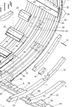
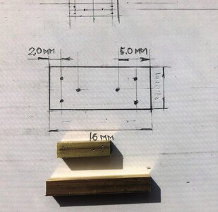
Thank you for your feedback. The proposed bolting pattern is only for a long plain scarphs, similar to frame #16. For all the 'chocked' frames I will use five bolts patterns like in the book. I already made the jig (foto below).

IMG_1653.JPEG
 
but...it is also the weakest point to split the wood (inline).

in that case I'd go with #4 - looks great in your last picture by the way!

same question to you: "how" did you insert the latest pictures? all of them are now "fixed" inside the post, can not be enlarged anymore, the last one with the jig works again
 
same question to you: "how" did you insert the latest pictures? all of them are now "fixed" inside the post, can not be enlarged anymore, the last one with the jig works again
hello Markus. I insert photos the same way. I use my PC as a source of photos. I drag & drop them directly into the post. I am thinking, if an image cannot be enlarged, it will be shown as 'fixed'. I will check it out...Thanks!!
 
in that case I'd go with #4 - looks great in your last picture by the way!

same question to you: "how" did you insert the latest pictures? all of them are now "fixed" inside the post, can not be enlarged anymore, the last one with the jig works again
depending on the width of the photo - if the photo has a bigger width than space in the topic -> than is possible to widen to maximum. the software is doing it automatically
Kurz noch in Deutsch: Das ist meist beim Querformat, bei Hochkant-Fotos ist das maximum erreicht und kann nicht weiter vergrößert werden
 
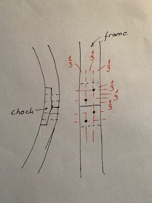
As far as I remember right you have to use four bolts for the chocks. If you look at the outside of the frames you can split the part of the frame where the cock sits in every direction in 3 parts. You get 4 section points. You need two in a diagonal order for the bolts.
I hope you understand, what I try to describe, if not I will post a sketch of the arrangement.
 
Last edited:
As far as I remember richt you have to use four bolts for the chocks. If you look at the outside of the Frames you can split the part of the frame where sth cock sits in every direction in 3 parts. You get 4 section points. You need two in a diagonal order for the bolts.
I hope you understand, what I try to describe, if not I will post a sketch of the arrangement.
Hi Christian,
Are you saying that 6 bolts in the chocks as shown in the AotS is wrong?
 
I can not say that this is wrong, therefore I need a primary source.

There are a lot of other inaccuracies and mistakes in the AotS of the Alert, so the book is in my opinion not a very trustable source. Goodwin gives for example the thickness of the frames in the text part of the book. But the frames in the drawing part are much thinner. If you have a look in the shipbuilder repository or in the Steel, you see that the info in the text part is right. For the stem construction I also could't find a historic source. The position of the horseshoe is also wrong. The function is to strength the joint between keel and lower stem.

This is the reason why I trust my other sources (for the position of the fastening it's Antscherl).
 
As far as I remember right you have to use four bolts for the chocks. If you look at the outside of the frames you can split the part of the frame where the cock sits in every direction in 3 parts. You get 4 section points. You need two in a diagonal order for the bolts.
I hope you understand, what I try to describe, if not I will post a sketch of the arrangement.
Many thanks for your response, Christian. If you can provide the sketch, that would be great!!
 
Back
Top