I know, I've not posted for a while and it is past due. Without further delay and explanation of what life is all about, I would like to rehabilitate. ") First, and most importantly, I would like to thanks everyone for visiting this blog, likes, and those who commented with questions and suggestions!
First, and most importantly, I would like to thanks everyone for visiting this blog, likes, and those who commented with questions and suggestions! ")
Frames saga (continue)...
In the last post, we've discussed cutting and assembling the frames. We use chock to attach floor timbers and first futtocks. Today, I would like to discuss the 'cant' frames. We have the Stem and Stern cant frames, and they have different names (depending on use purpose). Check out the few images from the AOTS book of Alert. * Images from the book for information purposes only.


Some of the names are 11- bollard timber, 10 - Hawse pieces. In any case, for us, in our build, we will call them 'cant' frames. The stem and\or bow section cant frames represented in the kit are from # 1 to 16 for bow and 58 to 71 for the stern. The first 6 bow frames are single (type 1, from the instruction manual), the rest of the frames are assembled using chocks or plain scarph joint. Contrary, the stern cant frames don't contain single frames and assembled using either chock or plain scarph joint. All frames must be assembled prior to beveling.
All cant (Stem and Stern) frames MUST be beveled or faired using the template prior to glue on the keel. I hope you save those (templates) when cut out from the frames MDF board. Each frame consists of two templates: for inside and outside shapes. (see photo below frame #5)

You must carefully trace the shape of the template, making sure it aligns across all the borders of the frame. I use clamps to hold down templates while tracing the line.
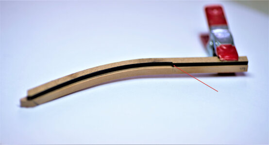
The template for outside beveling, the notch facing outside (red arrow)

The template for inside beveling, the notch facing inside the frame (red arrow)


The end-piece frame shown at the bottom will be glued to the rising wood, it has a very complex shape. Special care should be taken while shaping. I suggest leaving some 'meat' for final shaping. Take a look below.


Both templates together. Note that one template is longer than another, and the diagonal pencil line is the shaping border.

Most of the shaping done using the rotary tool and sandpaper drum. I cannot tell the grid of this sandpaper, but my big guess would be 320. It removes wood well, but leave some strike marks so be careful. Other 'finer' grids might be used, but will be less effective and will burn the timber. Also, you have to control both: the top and bottom sides. Use your 'thumb' finger as the rest for controlling pressure and the amount of removing material. Move the tool in one direction only - facing your body. Do I have to tell you to wear a mask?? I made small video clips to help with this process.
As you can see, it is not that difficult but time-consuming as you have to bevel both sides for each frame. Below are some photos with the final results. The idea of those templates is as simple as brilliant and I would like to compliment the @Trident Model


The final shape of the end-piece must be done while gluing to the keel.
The same way will be shaped\beveleed the stern cant frames including the 5 full frames. Make sure to retain the cut-outs from the frames MDF board.
to be continued...
First, and most importantly, I would like to thanks everyone for visiting this blog, likes, and those who commented with questions and suggestions! Frames saga (continue)...
In the last post, we've discussed cutting and assembling the frames. We use chock to attach floor timbers and first futtocks. Today, I would like to discuss the 'cant' frames. We have the Stem and Stern cant frames, and they have different names (depending on use purpose). Check out the few images from the AOTS book of Alert. * Images from the book for information purposes only.
Some of the names are 11- bollard timber, 10 - Hawse pieces. In any case, for us, in our build, we will call them 'cant' frames. The stem and\or bow section cant frames represented in the kit are from # 1 to 16 for bow and 58 to 71 for the stern. The first 6 bow frames are single (type 1, from the instruction manual), the rest of the frames are assembled using chocks or plain scarph joint. Contrary, the stern cant frames don't contain single frames and assembled using either chock or plain scarph joint. All frames must be assembled prior to beveling.
All cant (Stem and Stern) frames MUST be beveled or faired using the template prior to glue on the keel. I hope you save those (templates) when cut out from the frames MDF board. Each frame consists of two templates: for inside and outside shapes. (see photo below frame #5)
You must carefully trace the shape of the template, making sure it aligns across all the borders of the frame. I use clamps to hold down templates while tracing the line.
The template for outside beveling, the notch facing outside (red arrow)
The template for inside beveling, the notch facing inside the frame (red arrow)
The end-piece frame shown at the bottom will be glued to the rising wood, it has a very complex shape. Special care should be taken while shaping. I suggest leaving some 'meat' for final shaping. Take a look below.
Both templates together. Note that one template is longer than another, and the diagonal pencil line is the shaping border.
Most of the shaping done using the rotary tool and sandpaper drum. I cannot tell the grid of this sandpaper, but my big guess would be 320. It removes wood well, but leave some strike marks so be careful. Other 'finer' grids might be used, but will be less effective and will burn the timber. Also, you have to control both: the top and bottom sides. Use your 'thumb' finger as the rest for controlling pressure and the amount of removing material. Move the tool in one direction only - facing your body. Do I have to tell you to wear a mask?? I made small video clips to help with this process.
As you can see, it is not that difficult but time-consuming as you have to bevel both sides for each frame. Below are some photos with the final results. The idea of those templates is as simple as brilliant and I would like to compliment the @Trident Model
The final shape of the end-piece must be done while gluing to the keel.
The same way will be shaped\beveleed the stern cant frames including the 5 full frames. Make sure to retain the cut-outs from the frames MDF board.
to be continued...